Table of Contents
Advertisement
Quick Links
71M6531 Demo Board User's Manual
v1.5
71M6531 Demo Board
USER'S MANUAL
TERIDIAN Semiconductor Corporation
6440 Oak Canyon Rd., Suite 100
Irvine, CA 92618-5201
Phone: (714) 508-8800 ▪ Fax: (714) 508-8878
http://www.teridian.com/
meter.support@teridian.com
© 2007-2008 TERIDIAN Semiconductor Corporation
6/2/2008 5:23:00 PM
v1.5
Page: 1 of 83
Advertisement
Table of Contents

Related Manuals for Teridian 71M6531


Summary of Contents for Teridian 71M6531
- Page 1 71M6531 Demo Board User’s Manual 71M6531 Demo Board USER’S MANUAL 6/2/2008 5:23:00 PM v1.5 TERIDIAN Semiconductor Corporation 6440 Oak Canyon Rd., Suite 100 Irvine, CA 92618-5201 Phone: (714) 508-8800 ▪ Fax: (714) 508-8878 http://www.teridian.com/ meter.support@teridian.com v1.5 Page: 1 of 83...
- Page 2 71M6531 Demo Board User’s Manual Page: 2 of 83 v1.5 © 2007-2008 TERIDIAN Semiconductor Corporation...
- Page 3 71M6531 Demo Board User’s Manual TERIDIAN Semiconductor Corporation makes no warranty for the use of its products, other than expressly contained in the Company’s warranty detailed in the TERIDIAN Semiconductor Corporation standard Terms and Conditions. The company assumes no responsibility for any errors which may appear in this document, reserves the right to change devices or specifications detailed herein at any time without notice and does not make any commitment to update the information contained herein.
- Page 4 71M6531 Demo Board User’s Manual 71M6531 Single-Phase Energy Meter IC DEMO BOARD USER’S MANUAL Page: 4 of 83 v1.5 © 2007-2008 TERIDIAN Semiconductor Corporation...
-
Page 5: Table Of Contents
1.9.4 Updating Calibration Data in EEPROM or Flash ..................31 1.9.5 Loading the 6531_demo.hex file into the Demo Board................31 1.9.6 The Programming Interface of the 71M6531 ....................33 1.10 Demo Code ..............................34 1.10.1 Demo Code Description ..........................34 1.10.2... -
Page 6: List Of Figures
Figure 1-1: Demo Board: Basic Connections ....................... 10 Figure 1-2: Demo Board: Ribbon Cable Connections ....................11 Figure 1-3: The TERIDIAN 6531 Demo Board with Debug Board Block Diagram (CT Configuration) ......12 Figure 1-4: Port Configuration Setup ..........................14 Figure 1-5: Hyperterminal Sample Window with Disconnect Button ................ - Page 7 Figure 4-14: Debug Board: Middle Layer 2, Supply Plane ................... 79 Figure 4-15: Debug Board: Bottom Trace Layer ......................79 Figure 4-16: TERIDIAN 71M6531 LQFP64: Pinout (top view) ..................82 List of Tables Table 1-1: Jumper settings on Debug Board ........................ 13 Table 1-2: Straight cable connections ..........................
- Page 8 71M6531 Demo Board User’s Manual Page: 8 of 83 v1.5 © 2007-2008 TERIDIAN Semiconductor Corporation...
-
Page 9: Getting Started
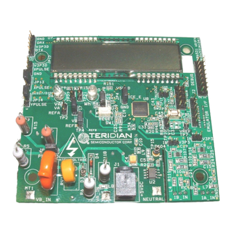
GETTING STARTED GENERAL The TERIDIAN Semiconductor Corporation (TSC) 71M6531 Demo Board is an energy meter IC demonstra- tion board for evaluating the 71M6531D/F device for residential electronic energy metering applications. It incorporates a 71M6531D/F integrated circuit, peripheral circuitry such as a serial EEPROM, emulator port, and on-board power supply as well as a companion Debug Board that allows a connection to a PC through a RS232 port. -
Page 10: Compatibility
71M6531 Demo Board User’s Manual COMPATIBILITY This manual applies to the following hardware and software revisions: • 71M6531D/F, chip revision A03 • Demo Boards D6531N12A2 • Demo Board Code revision 6531_4p6q_12may08_0cc.hex, 6531_4p6q_12may08_0sc.hex (EQU 0) , 6531_4p6q_12may08_1cc.hex EQU 1), 6531_4p6q_12may08_2cc.hex (EQU 2), or later... -
Page 11: Figure 1-2: Demo Board: Ribbon Cable Connections
Figure 1-2: Demo Board: Ribbon Cable Connections The 71M6531 Demo Board block diagram is shown in Figure 1-3. It consists of a stand-alone meter Demo Board and an optional Debug Board. The Demo Board contains all circuits necessary for operation as a meter, including display, calibration LED, and power supply. -
Page 12: Power Supply Setup
GND_DBG JP21 4/12/2007 Figure 1-3: The TERIDIAN 6531 Demo Board with Debug Board Block Diagram (CT Configuration) Note: All analog input signals are referenced to the V3P3A net (3.3V power supply to the chip). 1.6.1 POWER SUPPLY SETUP There are several choices for meter the power supply: •... -
Page 13: Cable For Serial Connection
71M6531 Demo Board User’s Manual 1.6.2 CABLE FOR SERIAL CONNECTION For connection of the DB9 serial port to a PC, either a straight or a so-called “null-modem” cable may be used. JP1 and JP2 are plugged in for the straight cable, and JP3/JP4 are empty. The jumper configuration is reversed for the null-modem cable, as shown in Table 1-3. -
Page 14: Serial Connection Setup For The Pc
71M6531 Demo Board User’s Manual 1.6.4 SERIAL CONNECTION SETUP FOR THE PC After connecting the DB9 serial port to a PC, start the HyperTerminal application (or any other suitable communication program) and create a session using the communication parameters shown in Table 1-4. -
Page 15: Using The Demo Board
1.7.1 CYCLING THE LCD DISPLAY The Demo Codes for the 71M6531 Demo Board allow cycling of the display using the PB button. By briefly pressing the button, the next available parameter from Table 1-5 is selected. This makes it easy to navigate various displays for Demo Boards that do not have the CLI. -
Page 16: Serial Command Line Interface (Cli)
71M6531 Demo Board User’s Manual Step Text Display Displayed Parameter Accumulated real energy [Wh]. The default display setting after power-up or reset. VARh Accumulated reactive energy [VARh]. Hours Expired hours after power-up or reset Time Time of day (hh.mm.ss). Date Date (yyyy.mm.dd). - Page 17 71M6531 Demo Board User’s Manual Commands for CE Data Access: CE DATA ACCESS Remarks Description: Allows user to read from and write to CE data space. Usage: ] [Starting CE Data Address] [option]…[option] Command ]??? Read consecutive 16-bit words in Decimal...
- Page 18 71M6531 Demo Board User’s Manual Commands for I/O RAM (Configuration RAM) and SFR Control: DIO AND SFR CONTROL Remarks Description: Allows the user to read from and write to I/O RAM and special function registers (SFRs). Usage: R [option] [register] … [option] Command RIx…...
- Page 19 71M6531 Demo Board User’s Manual Commands controlling the CE: COMPUTE ENGINE Remarks CONTROL Description: Allows the user to enable and configure the compute engine. Usage: C [option] [argument] Command Compute Engine Enable (1 Enable, 0 Disable) combinations: Select input n for TMUX output pin. Enter n in hex notation.
- Page 20 71M6531 Demo Board User’s Manual Commands for Controlling the Metering Values Shown on the LCD Display: METER DISPLAY Remarks CONTROL (LCD) Description: Allows user to select internal variables to be displayed. Usage: M [option]. [option] Command kWh Total Consumption (display wraps around at 999.999) combinations: Temperature (C°...
- Page 21 71M6531 Demo Board User’s Manual Commands for Controlling the RTC: REAL TIME CLOCK Remarks CONTROL Description: Allows the user to read and set the real time clock. Usage: RT [option] [value] … [value] Command RTDy.m.d.w: Day of week (year, month, day, weekday [1 = Sunday]). Weekday is combinations: automatically set if omitted.
-
Page 22: Communicating Via Intel Hex Records
71M6531 Demo Board User’s Manual Commands for Error Recording: ERROR RECORDING Remarks Description: Allows the user display and clear the error log. Usage: ER [option] [value] Command Clears all errors from error log combinations: Displays error log ERS+n Enters error number n in error log... -
Page 23: Table 1-7: Data (Command) Types
71M6531 Demo Board User’s Manual As opposed to the standardized Hex-records that offer three possible types (data, termination, segment base), six different types are supported for communicating with the 71M6531D/F. These data types basically encode command types (read/write) along with the data source or destination, as listed in Table 1-7. -
Page 24: Using The Battery Modes
71M6531 Demo Board User’s Manual Spaces in between the fields (to increase readability), as in the example above, are ignored by the Demo Boards. If a hex record is accepted, the Demo Board returns a " ". If the hex record is not accepted, the Demo Board sends a "... -
Page 25: Using The Demo Board For Metering Functions
71M6531 Demo Board User’s Manual mode, and the command prompt “B” will be visible on the terminal connected to the Demo Board, followed by the “>” sign: B> The LCD displays a decimal dot in the left-most digit to indicate that it is in Brownout mode, as shown below: The following commands can be entered via the CLI in Brownout mode: •... -
Page 26: Adjusting The Kh Factor For The Demo Board
1.8.3 ADJUSTING THE KH FACTOR FOR THE DEMO BOARD The 71M6531 Demo Board is shipped with a pre-programmed scaling factor Kh of 1.0, i.e. 1.0 Wh per pulse. In order to be used with a calibrated load or a meter calibration system, the board should be connected to the AC power source using the spade terminals on the bottom of the board. -
Page 27: Adjusting The Demo Boards To Different Ct Winding Ratios
1.8.6 WIRING OF THE DEMO BOARD AND A SHUNT RESISTOR The 71M6531 Demo Kits are shipped with a pre-wired shunt resistor (400µΩ), as shown in Figure 1-6. This shunt resistor has to be connected to the 71M6531 Demo Board, as shown in Figure 1-7. -
Page 28: Figure 1-6: Pre-Wired Shunt Resistor
71M6531 Demo Board User’s Manual to IA reference to IA_IN to meter power supply from LOAD NEUTRAL Figure 1-6: Pre-wired shunt resistor Important safety precautions apply when operating the Demo Board in shunt mode: In shunt configuration, the whole Demo Board will be at line voltage! Touching the board or any... -
Page 29: Figure 1-7: Connection Of The Pre-Wired Shunt Resistor
71M6531 Demo Board User’s Manual SHUNT NEUTRAL Low crosstalk demands that these current paths These wires must be not share a common connected directly at wire. the shunt resistor BLUE LOAD WHITE Power supply and Signal for reference for voltage... -
Page 30: Calibration Parameters
71M6531 Demo Board User’s Manual CALIBRATION PARAMETERS 1.9.1 GENERAL CALIBRATION PROCEDURE Any calibration method can be used with the 71M6531D/F chips. This Demo Board User’s Manual presents calibration methods with three or five measurements as recommended methods, because they work with most manual calibration systems based on counting "pulses"... -
Page 31: Calibration Macro File
Programming of the flash memory requires a specific in-circuit emulator, the ADM51 by Signum Systems (http//www.signumsystems.com) or the Flash Programmer (TFP-2) provided by TERIDIAN Semiconductor. Chips may also be programmed before they are soldered to the board. The TGP1 gang programmer suitable for high-volume production is available from TERIDIAN. -
Page 32: Figure 1-9: Emulator Window Showing Reset And Erase Buttons
71M6531 Demo Board User’s Manual At this point, the emulator probe (cable) can be removed. Once the 71M6531D/F IC is reset using the reset button on the Demo Board, the new code starts executing. Figure 1-9: Emulator Window Showing Reset and Erase Buttons Figure 1-10: Emulator Window Showing Erased Flash Memory and File Load Menu Flash Downloader Module (TFP-2): Follow the instructions given in the User Manual for the TFP-2. -
Page 33: The Programming Interface Of The 71M6531
71M6531 Demo Board User’s Manual Emulators or other test equipment should never be connected to a live meter without proper isolation! USB isolators are available from various vendors (see the printed Safety Notice shipped with the emulator). 1.9.6 THE PROGRAMMING INTERFACE OF THE 71M6531D/F... -
Page 34: Demo Code
It provides libraries for access of low-level IC functions to serve as building blocks for code development. The Demo Code source files provided with the TERIDIAN Demo Kits contain numerous routines that are not implemented. However, by recompiling the code using different compile-time options, many code variations with different features can be generated. - Page 35 71M6531 Demo Board User’s Manual Name Purpose Function or LSB Value L in XDATA bits Starting current, 0x0000 SQSUM IThrshldA element A 0 in this position disables creep logic for both element A and B. Configure meter bit 0:** reserved...
- Page 36 71M6531 Demo Board User’s Manual Name Purpose Function or LSB Value L in XDATA bits Current value to be Nominal RMS current applied to 0x0023 Ical used for autocalibra- all elements during auto-calibra- tion tion (LSB = 0.1V). Power factor must be 1.
- Page 37 71M6531 Demo Board User’s Manual Name Purpose Function or LSB Value L in XDATA bits Vrms, element A 0x004C SQSUM Vrms_A Irms, element A 0x0050 SQSUM Irms_A Vrms, element B 0x0054 SQSUM Vrms_B Irms, element B 0x0058 SQSUM Irms_B (reserved)
-
Page 38: Table 1-12: Mpu Memory Locations
71M6531 Demo Board User’s Manual Name Purpose Function or LSB Value L in XDATA bits LSB of W0SUM Exported VARh, all 0x00EC VARhe elements. Exported VARh, “ 0x00F4 VARhe_A element A Exported VARh, “ 0x00FC VARhe_B element B (reserved) 0x0104... -
Page 39: Table 1-13: Values For Pulse Source Registers
71M6531 Demo Board User’s Manual Table 1-13 lists the possible entries for the PULSEWSOURCE and PULSEVSOURCE registers. Decimal Value in Decimal Value in PULSEWSOURCE, Selected Pulse Source PULSEWSOURCE, Selected Pulse Source PULSEVSOURCE PULSEVSOURCE EQU= 0: W0SUM if W0SUM > W1SUM, W1SUM (reserved) if W1SUM >... -
Page 40: Table 1-14: Status Register
71M6531 Demo Board User’s Manual Table 1-14 explains the bits of the STATUS register. Significance Significance CREEP: All elements are in creep mode. The pulse variables will be “jammed” with a constant value on BATTERY_BAD: The battery voltage is below every accumulation interval to prevent spurious VBatMin. -
Page 41: Emulator Operation
71M6531 Demo Board User’s Manual MPU ACCUMULATION OUTPUT VARIABLES Accumulation values are accumulated from XFER cycle to XFER cycle (see Table 1-15). They are organized as two 32-bit registers. The first register stores the decimal number displayed on the LCD. For example, if the LCD shows “001.004”, the value in the first register is 1004. - Page 42 71M6531 Demo Board User’s Manual Page: 42 of 83 v1.5 © 2007-2008 TERIDIAN Semiconductor Corporation...
-
Page 43: Application Information
71M6531 Demo Board User’s Manual APPLICATION INFORMATION CALIBRATION THEORY A typical meter has phase and gain errors as shown by φ , and A in Figure 2-1. Following the typical meter convention of current phase being in the lag direction, the small amount of phase lead in a typical current sensor is represented as -φ... - Page 44 71M6531 Demo Board User’s Manual From the voltage measurement, we determine that We use the other two measurements to determine φ and A φ − cos( φ − − cos( cos( φ cos( φ φ − − cos( cos( −...
-
Page 45: Calibration With Five Measurements
71M6531 Demo Board User’s Manual And we calculate the new calibration current gain coefficient, including compensation for a slight gain increase in the phase calibration circuit. − − − π − − PHADJ PHADJ cos( − π − − −... -
Page 46: Fast Calibration
71M6531 Demo Board User’s Manual φ − tan( tan( ⎛ ⎞ − ⎜ ⎜ ⎟ ⎟ φ − ⎝ ⎠ tan( Now that we know the A , and φ errors, we calculate the new calibration voltage gain coefficient from the previous ones: We calculate PHADJ from φ... -
Page 47: Calibration Procedures
71M6531 Demo Board User’s Manual is determined by comparing applied real energy with the measured apparent energy (and CAL_IA compensating for the change applied to CAL_VA ⋅ 16384 ⋅ applied ⋅ measured The derivation of these formulae is shown in the Appendix. -
Page 48: Calibration Procedure With Three Measurements
Store the new calibration factors CAL_IA, CAL_VA, and PHADJ_A in the EEPROM of the meter. If the calibration is performed on a TERIDIAN Demo Board, the methods shown in sections 1.9.2 can be used. -
Page 49: Procedure For Auto-Calibration
Check the calibration factors established by the automatic procedure. 2.2.5 CALIBRATION SPREADSHEETS Calibration spreadsheets are available from TERIDIAN Semiconductor. They are also included in the CD- ROM shipped with any Demo Kit. Figure 2-3 shows the spreadsheet for three measurements with three phases in use (only one phase needs to be used for the 71M6531D/F chip). -
Page 50: Figure 2-4: Calibration Spreadsheet For Five Measurements
71M6531 Demo Board User’s Manual 71M6511/71M6513/71M6515 Calibration Worksheet Five Measurements Results will show in green fields… Enter values in yellow fields! Date: 10/25/2005 AC frequency: [Hz] (click on yellow field to select from pull-down list) fraction PHASE A Voltage Energy reading at 0°... -
Page 51: Compensating For Non-Linearities
71M6531 Demo Board User’s Manual 2.2.6 COMPENSATING FOR NON-LINEARITIES Nonlinearity is most noticeable at low currents, as shown in Figure 2-6, and can result from input noise and truncation. Nonlinearities can be eliminated using the QUANT variable. error I [A] Figure 2-6: Non-Linearity Caused by Quantification Noise The error can be seen as the presence of a virtual constant noise current. -
Page 52: Figure 2-7: 71M6531 With Shunt And Ct
Before starting a calibration, all calibration factors must be in their default state, i.e. CAL_IA (0x10), CAL_VA (0x11), CAL_IB (0x12) must be 16384. PHADJ_A (0x18) and PHADJ_B (0x19) should be zero. SHUNT LIVE LOAD NEUT 71M6531 71M6511 V3P3 Figure 2-7: 71M6531 with Shunt and CT Page: 52 of 83 v1.5 © 2007-2008 TERIDIAN Semiconductor Corporation... - Page 53 The value obtained for IMAX_SHUNT is stored at the MPU address 0x0A, using the command IMAX_SHUNT of the Demo Code supplied by TERIDIAN. Compute WRATE_SHUNT based on IMAX_SHUNT and VMAX and the formula given in 1.8.3: WRATE_SHUNT = (IMAX_SHUNT * VMAX * 47.1132) / (Kh * In_8 *...
-
Page 54: Calibrating And Compensating The Rtc
71M6531 Demo Board User’s Manual That is, if the chip reports an error of -2.5%, CAL_IB should be adjusted to a value of (16384 * (1 - (-2.5/100)). Since CAL_VA and CAL_IA have already been adjusted for channel A, these registers should not be updated. -
Page 55: Testing The Demo Board
Demo Code adjusts the oscillator within very narrow limits. The MPU Demo Code supplied with the TERIDIAN Demo Kits has a direct interface for these coefficients and it directly controls the PREG[16:0] and QREG[1:0] registers. The Demo Code uses the coefficients in the... -
Page 56: Eeprom
Figure 2-8: Meter with Calibration System TERIDIAN Demo Boards are not calibrated prior to shipping. However, the Demo Board pulse outputs are tested and compared to the expected pulse output. Figure 2-9 shows the screen on the controlling PC for a typical Demo Board. -
Page 57: Rtc
The LCD_CLK register determines the frequency at which the COM pins change states. A slower clock means lower power consumption, but if the clock is too slow, visible flicker can occur. The default clock frequency for the 71M6531 Demo Boards is 150Hz (LCD_CLK = 01). v1.5 Page: 57 of 83 ©... -
Page 58: Supply Current Measurements
The jumper on JP4 should be moved to position 1-2 in order to save the current required to supply the ICE_E pin. TERIDIAN APPLICATION NOTES Please contact your local TERIDIAN sales representative for TERIDIAN Application Notes. Page: 58 of 83 v1.5... -
Page 59: Hardware Description
2-pin header used as a selector for the driving source of LED D5. In JP13 XPULSE default setting (1-2), the VARPULSE (DIO7) drives the LED. The alternative selection causes the YPULSE output to drive the LED. Table 3-1: 71M6531 Demo Board description: 1/3 v1.5 Page: 59 of 83 © 2007-2008 TERIDIAN Semiconductor Corporation... -
Page 60: Table 3-2: 71M6531 Demo Board Description: 2/3
2-pin header representing the V1 comparator voltage input test TP10 V1, V3P3 point and ground. A jumper should be placed between V1 and V3P3 to disable the watchdog timer. Table 3-2: 71M6531 Demo Board description: 2/3 Page: 60 of 83 v1.5 © 2007-2008 TERIDIAN Semiconductor Corporation... -
Page 61: Table 3-3: 71M6531 Demo Board Description: 3/3
This is the NEUTRAL line voltage input. It is connected to the 3.3V NEUTRAL net of the 71M6531D/F. The neutral wire is connected to the spade terminal on the bottom of the board. Table 3-3: 71M6531 Demo Board description: 3/3 v1.5 Page: 61 of 83 © 2007-2008 TERIDIAN Semiconductor Corporation... -
Page 62: Figure 3-1: 71M6531N12A2 Board Connectors, Jumpers, Switches, And Test Points
71M6531 Demo Board User’s Manual Figure 3-1: 71M6531N12A2 Board Connectors, Jumpers, Switches, and Test Points Page: 62 of 83 v1.5 © 2007-2008 TERIDIAN Semiconductor Corporation... -
Page 63: Demo Board Hardware Specifications
71M6531 Demo Board User’s Manual DEMO BOARD HARDWARE SPECIFICATIONS PCB Dimensions Dimensions 3.625” x 3.625” (92.075mm x 92.075mm) Thickness 0.062” (1.6mm) Height w/ components 2.0” (51mm) Environmental Operating Temperature -40°…+85°C (accuracy of crystal oscillator affected outside –10°C to +60°C) Storage Temperature -40°C…+100°C... - Page 64 71M6531 Demo Board User’s Manual Page: 64 of 83 v1.5 © 2007-2008 TERIDIAN Semiconductor Corporation...
-
Page 65: Appendix
71M6531 Demo Board User’s Manual APPENDIX This appendix includes the following documentation, tables and drawings: Demo Board Schematics Demo Board Bills of Materials (Parts Lists - BOM) Demo Board PCB Layout Views Debug Board Description Debug Board Electrical Schematic Debug Board Bill of Materials... -
Page 66: 71M6531N12A2 Demo Board Electrical Schematic
600 OHM 600 OHM IB_IN IB_IN ' R104 750 1% TP19 TERIDIAN SEMICONDUCTOR CORP. R106 R107 Title 71M6531 Demo Board Schematic 68 Pin Package 4W, 2PH 1000pF Size Document Number 1000pF 1000pF V3P3 D6531N12A2 Date: Friday, December 14, 2007 Sheet Figure 4-1: 71M6531N12A2 Demo Board (REV 2.0): Electrical Schematic 1/3 –... -
Page 67: Figure 4-2: 71M6531N12A2 Demo Board (Rev 2.0): Electrical Schematic 2/3 - Ct Configuration
R106 R107 1000pF TERIDIAN SEMICONDUCTOR CORP. 1000pF 1000pF Title V3P3 71M6531 Demo Board Schematic 68 Pin Package 4W, 2PH Size Document Number Custom D6531N12A2 Date: Tuesday, December 18, 2007 Sheet Figure 4-2: 71M6531N12A2 Demo Board (REV 2.0): Electrical Schematic 2/3 – CT Configuration v1.5... -
Page 68: Figure 4-3: 71M6531N12A2 Demo Board (Rev 2.0): Electrical Schematic 3/3 - Digital Section
OPT_RX/DIO1 V3P3D 100pF 6531-68QFN JP14 TERIDIAN SEMICONDUCTOR CORP. 1000pF Title 71M6531 Demo Board Schematic 68 Pin Package 4W, 2PH V3P3 Size Document Number D6531N12A2 Date: Friday, December 14, 2007 Sheet Figure 4-3: 71M6531N12A2 Demo Board (REV 2.0): Electrical Schematic 3/3 – Digital Section Page: 68 of 83 v1.5... -
Page 69: 71M6531N12A2 Demo Board Bill Of Material
71M6531 Demo Board User’s Manual 71M6531N12A2 DEMO BOARD BILL OF MATERIAL Digi-Key/Mouser Part Item Reference Part Part Number Manufacturer Footprint Number 2200uF radial P5143-ND ECA-1CM222 Panasonic C2,C4,C22 10uF RC1812 478-1672-1-ND TAJB106K010R RC0603 PCC2224CT-ND ECJ-1VB1C105K Panasonic C5,C17,C19,C20,C23,C27,C28, 0.1uF RC0603 445-1314-1-ND C1608X7R1H104K... -
Page 70: 71M6531N12A2 Demo Board Pcb Layout
71M6531 Demo Board User’s Manual 71M6531N12A2 DEMO BOARD PCB LAYOUT Figure 4-4: 71M6531N12A2 Demo Board: Top Silk Screen Page: 70 of 83 v1.5 © 2007-2008 TERIDIAN Semiconductor Corporation... -
Page 71: Figure 4-5: 71M6531N12A2 Demo Board: Top Copper Layer
71M6531 Demo Board User’s Manual Figure 4-5: 71M6531N12A2 Demo Board: Top Copper Layer v1.5 Page: 71 of 83 © 2007-2008 TERIDIAN Semiconductor Corporation... -
Page 72: Figure 4-6: 71M6531N12A2 Demo Board: Bottom View With Silk Screen
71M6531 Demo Board User’s Manual Figure 4-6: 71M6531N12A2 Demo Board: Bottom View with Silk Screen Page: 72 of 83 v1.5 © 2007-2008 TERIDIAN Semiconductor Corporation... -
Page 73: Figure 4-7: 71M6531N12A2 Demo Board: Bottom Copper Layer - Bottom View
71M6531 Demo Board User’s Manual Figure 4-7: 71M6531N12A2 Demo Board: Bottom Copper Layer – Bottom View v1.5 Page: 73 of 83 © 2007-2008 TERIDIAN Semiconductor Corporation... -
Page 74: Figure 4-8: 71M6531N12A2 Demo Board: Bottom Copper Layer - Layer View From Top
71M6531 Demo Board User’s Manual Figure 4-8: 71M6531N12A2 Demo Board: Bottom Copper Layer – Layer View from Top Page: 74 of 83 v1.5 © 2007-2008 TERIDIAN Semiconductor Corporation... -
Page 75: Debug Board Bill Of Material
71M6531 Demo Board User’s Manual DEBUG BOARD BILL OF MATERIAL Item Quantity Reference Part PCB Footprint Digi-Key Part Number Part Number Manufacturer 445-1349-1-ND C1-C3,C5-C10,C12-C23 0.1uF RC0805 C2012X7R1H104K 33uF, 10V RC1812 478-1687-1-ND TAJB336K010R 10uF, 16V RC1812 478-1673-1-ND TAJB106K016R D2,D3 RC0805 160-1414-1-ND... -
Page 76: Debug Board Schematics
71M6531 Demo Board User’s Manual DEBUG BOARD SCHEMATICS V5_DBG 0.1uF 0.1uF GND_DBG V3P3 VDD1 VDD2 V5_DBG GND2 DIO02 VDD1 DOUT GND_DBG GND1 GND2 V5_DBG 5Vdc EXT SUPPLY V5_DBG DISPLAY SEL ADUM1100 GND_DBG 0.1uF GND_DBG V5_DBG 33uF, 10V 0.1uF RAPC712 GND_DBG 0.1uF... -
Page 77: Debug Board Pcb Layout
71M6531 Demo Board User’s Manual DEBUG BOARD PCB LAYOUT Figure 4-10: Debug Board: Top View Figure 4-11: Debug Board: Bottom View v1.5 Page: 77 of 83 © 2007-2008 TERIDIAN Semiconductor Corporation... -
Page 78: Figure 4-12: Debug Board: Top Signal Layer
71M6531 Demo Board User’s Manual Figure 4-12: Debug Board: Top Signal Layer Figure 4-13: Debug Board: Middle Layer 1, Ground Plane Page: 78 of 83 v1.5 © 2007-2008 TERIDIAN Semiconductor Corporation... -
Page 79: Figure 4-14: Debug Board: Middle Layer 2, Supply Plane
71M6531 Demo Board User’s Manual Figure 4-14: Debug Board: Middle Layer 2, Supply Plane Figure 4-15: Debug Board: Bottom Trace Layer v1.5 Page: 79 of 83 © 2007-2008 TERIDIAN Semiconductor Corporation... -
Page 80: Teridian 71M6531 Pin-Out Information
71M6531 Demo Board User’s Manual TERIDIAN 71M6531D/F PIN-OUT INFORMATION Power/Ground/NC Pins Name Type Circuit Description GNDA Analog ground: This pin should be connected directly to the ground plane. GNDD Digital ground: This pin should be connected directly to the ground plane. - Page 81 71M6531 Demo Board User’s Manual Digital Pins: Name Type Circuit Description COM3, COM2, LCD Common Outputs: These 4 pins provide the select signals for the LCD COM1, display. COM0 SEG0…SEG2, Dedicated LCD Segment Output pins. SEG7, SEG8, SEG12…SEG18 COM3, COM2,...
-
Page 82: Figure 4-16: Teridian 71M6531 Lqfp64: Pinout (Top View)
IE_PB flag. It also causes the part to wake up if it is in SLEEP or LCD mode. PB does not have an internal pull-up or pull-down. Table 4-4: 71M6531D/F Pin description 2/2 PINOUT (QFN 68) Figure 4-16: TERIDIAN 71M6531D/F LQFP64: Pinout (top view) Page: 82 of 83 v1.5 © 2007-2008 TERIDIAN Semiconductor Corporation... -
Page 83: Revision History
(top-view). User Manual: This User Manual contains proprietary product definition information of TERIDIAN Semiconductor Corporation (TSC) and is made available for informational purposes only. TERIDIAN assumes no obligation regarding future manufacture, unless agreed to in writing. If and when manufactured and sold, this product is sold subject to the terms and conditions of sale supplied at the time of order acknowledgment, including those pertaining to warranty, patent infringement and limitation of liability. - Page 84 Mouser Electronics Authorized Distributor Click to View Pricing, Inventory, Delivery & Lifecycle Information: Maxim Integrated 71M6531F-DB...
Need help?
Do you have a question about the 71M6531 and is the answer not in the manual?
Questions and answers