
Related Manuals for Teridian 73S1215F


Summary of Contents for Teridian 73S1215F
- Page 1 Simplifying System Integration 73S1215F Evaluation Board Lite User Guide August 17, 2009 Rev. 1.1 UG_1215F_045...
- Page 2 Fedora is a registered trademark of RedHat, Inc. All other trademarks are the property of their respective owners. Teridian Semiconductor Corporation makes no warranty for the use of its products, other than expressly contained in the Company’s warranty detailed in the Teridian Semiconductor Corporation standard Terms and Conditions.
-
Page 3: Table Of Contents
Driver and Software Installation................... 10 3.1.1 Installation on Windows XP ..................10 3.1.2 Installation on a Linux System ................... 11 Frequently Asked Questions ....................11 73S1215F Evaluation Board Lite Hardware Description ............13 Jumpers, Switches and Test Points..................13 Schematic........................... 16 PCB Layouts........................17 Bill of Materials ........................ - Page 4 Figure 3: Emulator Window Showing RESET and ERASE Buttons ............9 Figure 4: Emulator Window Showing Erased Flash Memory and File Load Menu ........9 Figure 5: 73S1215F Evaluation Board Lite Jumper, Switch and Test Point Location ....... 15 Figure 6: 73S1215F Evaluation Board Lite Electrical Schematic ............. 16 Figure 7: 73S1215F Evaluation Board Lite Top View (Silkscreen) ............
-
Page 5: Introduction
1 Introduction The Teridian Semiconductor Corporation (TSC) 73S1215F Evaluation Board Lite is used to demonstrate the capabilities of the 73S1215F Smart Card Controller devices. It has been designed to operate either as a standalone or a development platform. The 73S1215F Evaluation Board Lite can be programmed to run any of the Teridian turnkey applications or a user-developed custom application. -
Page 6: Evaluation Board Lite Package Contents
• ICE/Programmer interface • Real Time Clock (RTC) capability • 4 LEDs Recommended Equipment and Test Tools The following equipment and tools (not provided) are recommended for use with the 73S1215F Evaluation Board Lite package: • ® ® ® ®... -
Page 7: Evaluation Board Lite Basic Setup
A standard RS-232 serial interface (TX/RX only). The board provides by default the USB CCID application. Refer to Section 3 for information to set up and run the USB CCID application. Figure 2: 73S1215F Evaluation Board Lite Basic Connections Rev. 1.1... -
Page 8: Connecting The Evaluation Board Lite With An Emulation Tool
Loading Code with the In-Circuit Emulator If firmware exists in the 73S1215F flash memory, the memory must be erased before loading a new file into memory. In order to erase the flash memory, the RESET button in the emulator software must be... -
Page 9: Figure 3: Emulator Window Showing Reset And Erase Buttons
UG_1215F_045 73S1215F Evaluation Board Lite User Guide RESET BUTTON ERASE BUTTON Figure 3: Emulator Window Showing RESET and ERASE Buttons Figure 4: Emulator Window Showing Erased Flash Memory and File Load Menu Rev. 1.1... -
Page 10: Using The Usb Ccid Application
UG_1215F_045 3 Using the USB CCID Application The USB CCID firmware is pre-installed on the 73S1215F Evaluation Board Lite. To operate correctly it requires a PC with the appropriate driver installed to be connected through its USB port. When powered- up, the board is able to run with the demonstration host application included on the CD. -
Page 11: Installation On A Linux System
USB host. If the problem persists, check the driver on the PC to make sure it is at least version 6.0.0.2. Contact your Teridian Sales Rep for the latest version of the driver. Sometimes, rebooting the PC Host to clear up any previous USB problem will help to resolve the problem. - Page 12 73S1215F Evaluation Board Lite User Guide UG_1215F_045 Q: The Teridian Smart Reader is nowhere to be found on the Device Manager menu and there is an “unknown USB device” found where the Teridian Development Board should be. A: This usually means the development board is properly powered up but there is no enumeration taking place.
-
Page 13: 73S1215F Evaluation Board Lite Hardware Description
4 73S1215F Evaluation Board Lite Hardware Description Jumpers, Switches and Test Points Table 2 describes the 73S1215F Evaluation Board Lite jumpers, switches and test points. The Item # in Table 2 references Figure 5. The default setting refers to setup for running USB-CCID application. - Page 14 73S1215F Evaluation Board Lite User Guide UG_1215F_045 Schematic Item Default Name Silkscreen setting Reference for interrupt). Remove this jumper if not needed and USR7 can be used for another purpose. – Board reference and serial Should be mentioned in any communication number with Teridian when requesting for support.
-
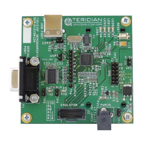
Page 15: Figure 5: 73S1215F Evaluation Board Lite Jumper, Switch And Test Point Location
UG_1215F_045 73S1215F Evaluation Board Lite User Guide Figure 5: 73S1215F Evaluation Board Lite Jumper, Switch and Test Point Location Rev. 1.1... -
Page 16: Schematic
Length and width of USB D+ and D- tracks 3.3V should be matched and routed away from smart card CLK and VCCs VBUS VBUS +5VDC 100k MOUNT HOLES FOR STAND OFFS 0.1uF USB_CONN_4 200k VBUS_MON Enable Figure 6: 73S1215F Evaluation Board Lite Electrical Schematic Rev. 1.1... -
Page 17: Pcb Layouts
UG_1215F_045 73S1215F Evaluation Board Lite User Guide PCB Layouts Figure 7: 73S1215F Evaluation Board Lite Top View (Silkscreen) Figure 8: 73S1215F Evaluation Board Lite Bottom View (Silkscreen) Rev. 1.1... -
Page 18: Figure 9: 73S1215F Evaluation Board Lite Top Signal Layer
73S1215F Evaluation Board Lite User Guide UG_1215F_045 Figure 9: 73S1215F Evaluation Board Lite Top Signal Layer Figure 10: 73S1215F Evaluation Board Lite Middle Layer 1 – Ground Plane Rev. 1.1... -
Page 19: Figure 11: 73S1215F Evaluation Board Lite Middle Layer 2 - Supply Plane
UG_1215F_045 73S1215F Evaluation Board Lite User Guide Figure 11: 73S1215F Evaluation Board Lite Middle Layer 2 – Supply Plane Figure 12: 73S1215F Evaluation Board Lite Bottom Signal Layer Rev. 1.1... -
Page 20: Bill Of Materials
73S1215F Evaluation Board Lite User Guide UG_1215F_045 Bill of Materials Table 3 provides the bill of materials for the 73S1215F Evaluation Board Lite schematic provided in Figure Table 3: 73S1215F Evaluation Board Lite Bill of Materials Digi-key Part Item Qty. Reference... - Page 21 UG_1215F_045 73S1215F Evaluation Board Lite User Guide Digi-key Part Item Qty. Reference Part PCB Footprint Part Number Manufacturer Number 10 kΩ P10KGCT-ND ERJ-3GEYJ103V Panasonic 62 Ω R7,R9,R10,R13-R17 P62GCT-ND ERJ-3GEYJ620V Panasonic 1 MΩ P1.0MGCT-ND ERJ-3GEYJ106V Panasonic Panasonic EVQ P8051SCT EVQ-PJX05M Panasonic...
-
Page 22: Schematic Information
The RTC oscillator drives a standard 32.768 kHz watch crystal. Crystals of this type are accurate and do not require a high current oscillator circuit. The oscillator in the 73S1215F has been designed specifically to handle watch crystals and is compatible with their high impedance and limited power handling capability. -
Page 23: Usb Interface
73S1215F Evaluation Board Lite User Guide 4.5.3 USB Interface The USB interface on the 73S1215F requires few external components for proper operation. Two serial resistors of 24 Ω ± 1% are needed to provide proper impedance matching for the USB data signals D+ and D-. -
Page 24: Figure 16: Smart Card Connections
73S1215F Evaluation Board Lite User Guide UG_1215F_045 • Keep CLK trace away from VCC and RST traces. Up to 30pF to ground is allowed for filtering • Keep 0.1µF close to VDD pin of the device and directly take other end to ground •... -
Page 25: Ordering Information
73S1215F Evaluation Board Lite Quick Start Guide TSC Flash Programmer Model TFP2 User’s Manual 7 Contact Information For more information about Teridian Semiconductor products or to check the availability of the 73S1215F contact us at: 6440 Oak Canyon Road Suite 100... -
Page 26: Revision History
73S1215F Evaluation Board Lite User Guide UG_1215F_045 Revision History Revision Date Description April 6, 2009 First Publication. August 17, 2009 Added information from the Quick Start Guide. Miscellaneous editorial modifications. Rev. 1.1...
Need help?
Do you have a question about the 73S1215F and is the answer not in the manual?
Questions and answers