Table of Contents
Advertisement
Quick Links
Advertisement
Table of Contents

Related Manuals for Optimum OPTIdrill B 16H


Summary of Contents for Optimum OPTIdrill B 16H
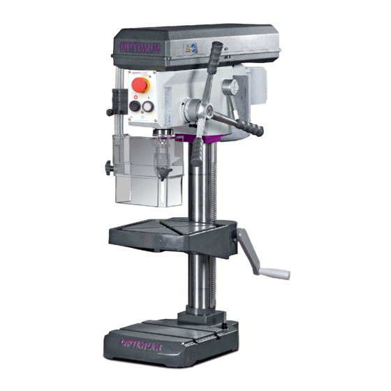
- Page 1 Operating Manual Version 2.0.1 Bench drill Part no. 3020217...
-
Page 2: Table Of Contents
Table of contents Safety Type plate ..............................5 Safety instructions (warning notes)........................ 6 1.2.1 Classification of hazards ........................6 1.2.2 Other pictograms..........................6 Intended use ..............................7 Reasonably foreseeable misuse........................7 1.4.1 Avoiding misuse ..........................8 Possible dangers caused by the bench drill ....................8 Qualification of personnel .......................... - Page 3 Switching off the machine ..........................24 Speed variation ............................25 Drill depth stop .............................25 4.6.1 Table height adjustment .........................26 Disassembly, assembly of drill chucks and drill bits ..................26 4.7.1 Fitting the drill chuck ........................26 4.7.2 Function of quick action drill chuck ....................27 4.7.3 Unfitting the drill chuck........................27 Cooling .................................28...
- Page 4 Dear customer, Thank you very much for purchasing a product made by OPTIMUM. OPTIMUM metal working machines offer a maximum of quality, technically optimum solutions and convince by an outstanding price performance ratio. Continuous enhancements and pro- duct innovations guarantee state-of-the-art products and safety at any time.
-
Page 5: Safety
Always keep this documentation close to the drilling machine. INFORMATION If you are unable to rectify an issue using these operating instructions, please contact us for advice: Optimum Maschinen Germany GmbH Dr. Robert-Pfleger-Str. 26 D-96103 Hallstadt email: info@optimum-maschinen.de Type plate... -
Page 6: Safety Instructions (Warning Notes)
Safety instructions (warning notes) 1.2.1 Classification of hazards We classify the safety warnings into different categories. The table below gives an overview of the classification of symbols (ideogram) and the warning signs for each specific danger and its (possible) consequences. Alarm expres- Symbol Definition / consequence... -
Page 7: Intended Use
If the bench drill is used in any way other than described above, modified without authorization of Optimum Maschinen Germany GmbH, then the geared drill is being used improperly. We will not be held liable for any damages resulting from any operation which is not in accor- dance with the intended use. -
Page 8: Avoiding Misuse
Any other use has to be discussed with the manufacturer. It is only permissible to process metal, cold and non-inflammable materials with the bench drill. In order to avoid misuse, it is necessary to read and understand the operating instructions before first commissioning. -
Page 9: Qualification Of Personnel
INFORMATION Everyone involved in the assembly, commissioning, operation and maintenance must be duly qualified, and strictly follow these operating instructions. In the event of improper use there may be a risk to personnel, there may be a risk to the machine and other material values, ... -
Page 10: Authorized Persons
Qualified personnel Due to their professional training, knowledge and experience as well as knowledge of relevant regulations, qualified personnel are able to perform the assigned tasks and to independently recognise and avoid any possible dangers. Instructed person Instructed persons were instructed by the operating company regarding the assigned tasks and any possible risks of improper behaviour. -
Page 11: Safety Measures During Operation
Safety measures during operation CAUTION! Danger due to inhaling dust and mist that is hazardous to health. Dependent on the material which need to be processed and the used auxiliaries dusts and mist may be caused which might impair you health. Ensure that the harmful dust and mist generated are safely sucked off at the point of origin and routed away from the working area or filtered. -
Page 12: Emergency-Stop Switch
Check that prohibition, warning and information signs and the labels on the bench drill. are legible (clean them, if necessary) are complete (replace if necessary). INFORMATION Organise the checks according to the following table; General check Equipment check Guards Mounted, firmly bolted and not damaged Signs,... -
Page 13: Drilling Table
1.12 Drilling table Seats for T-slots are attached to the clamping table. WARNING! Risk injury workpieces flying off at high speed. Securely workpiece on the drilling table. Seat for t-slot Abb.1-2: Drilling table 1.13 Separating protective devices 1.13.1 Protective cover of the V-belts A protective cover for the belt pulleys is mounted on the dril- ling head. -
Page 14: Personal Protective Equipment
1.14 Personal protective equipment For some works you need personnel protective equipment as protective equipment. These are Safety helmet, protective glasses or face guard, protective gloves, safety shoes with steel toe caps, ear protection. Before starting work make sure that the required personnel protective equipment is available at the work place. -
Page 15: 1.16.1 Disconnecting And Securing The Bench Drill
Check if they are working properly! 1.17 Accident report Inform your supervisors and Optimum Maschinen Germany GmbH immediately in the event of accidents, possible sources of danger and any actions which almost led to an accident (near misses). There are many possible causes for "near misses". -
Page 16: Technical Specification
Technical specification The following information represents the dimensions and indications of weight and the manu- facturer‘s approved machine data. Electrical connection 400V ~50 Hz Connection 0.55 kW Drilling capacity Drilling capacity in steel [mm] Drilling capacity in cast [mm] Continuous drilling capacity in steel [mm] Throat [mm] Spindle sleeve stroke [mm] Spindle seat... -
Page 17: Environmental Conditions
Environmental conditions Temperature 535 °C Relative humidity 25 - 80 % Operating material toothed rod commercial lubricating grease Column, bare steel parts acid-free oil, e.g. machine oil, motor oil Emissions The generation of noise emitted by the bench drill is lower than 76 dB(A). If the bench drill is installed in an area where various machines are in operation, the noise exposure (immission) on the operator of the milling machine at the working place may exceed 80 dB(A). -
Page 18: Dimensions
2.10 Dimensions Schwerpunkt / Centre of gravity Abb.2-1: B16H Technical specification Translation of the original instructions Version 2.0.1 - 2020-7-17... -
Page 19: Delivery, Interdepartmental Transport, Assembly And Commissioning
Delivery, interdepartmental transport, assembly and commissioning Notes on transport, installation, commissioning Improper transport, installation and commissioning is liable to accidents and can cause damage or malfunctions to the machine for which we do not assume any liability or guarantee. Transport the scope of delivery secured against shifting or tilting with a sufficiently dimen- sioned industrial truck or a crane to the installation site. -
Page 20: Scope Of Delivery
Scope of delivery When the machine is delivered, please check immediately that it has not been damaged during transport. Compare the scope of delivery with the attached packing list. Set-up and assembly 3.3.1 Installation site requirements Organise the working area around the bench drill according to the local safety regulations. INFORMATION In order to attain good functionality and a high processing accuracy as well as a long service life of the machine, the place of installation should fulfil certain criteria. -
Page 21: Fixing
Fix the bench drill in the provided through-holes on the machine foot. „Fixing“ auf Seite WARNING! The condition of the foundation and the fixing type of the machine foot to the foundation must be in a way that it can bear the loads of the bench drill. The foundation must be level. -
Page 22: Electrical Connection
3.4.3 First commissioning WARNING! First commissioning may only take place after proper installation. There is a danger to persons and equipment, if the first commissioning of the drilling machine is carried out by inexperienced personnel. We do not accept any liability for damages caused by incorrectly performed commissioning. -
Page 23: Operation
Operation Safety Commission the machine only under the following conditions: The machine is in proper working order. The machine is used as prescribed. The operating instructions are observed. All safety devices are installed and activated. All failures should be eliminated immediately. Stop the machine immediately in the event of any anomaly in operation and make sure it cannot be started up accidentally or without authoriza- tion. -
Page 24: Control Panel
4.2.1 Control panel Emergency-stop switch Push button "ON" Push button "OFF" Abb.4-1: Push button ON The push button "ON" switches on the rotation of the drilling spindle in preselected operating mode. Push button OFF The "push button OFF“ switches the rotation of the drilling spindle off. Master switch Interrupts or connects the power supply. -
Page 25: Speed Variation
Speed variation Switch off the machine by using the main switch. V-belt Open the protective cover. Loosen the lever of the V- belt tensioning. Lever Position the V-belt respec- V-belt tension tively on the required trans- mission stage. -
Page 26: Disassembly, Assembly Of Drill Chucks And Drill Bits
4.6.1 Table height adjustment Release the clamping lever on the drilling table. Use the hand crank to move the drilling table to the desired height. Retighten the clamping lever Clamping lever firmly. Crank handle Abb.4-4: Table height adjustment Disassembly, assembly of drill chucks and drill bits 4.7.1 Fitting the drill chuck... -
Page 27: Function Of Quick Action Drill Chuck
4.7.2 Function of quick action drill chuck The drill chuck consists of two parts (1 and 2) Hold the upper part (No.1) of the drill chuck. With the bot- tom part of the drill chuck (No. Upper part (No. 1) quick- 2) it is possible to tighten or action drill chuck loosen the jaws of the quick-... -
Page 28: Cooling
Cooling The friction generated during rotation can cause the edge of the tool to become very hot. The tool should be cooled during the drilling process. Cooling the tool with a suitable cooling lubricant ensures better working results and a longer edge life of the tools. This is best realised by a separate cooling equipment. - Page 29 WARNING! Seizing of clothes and / or hair. Make sure to wear well-fitting work during drilling work. Do not use gloves. If necessary, use a hairnet. CAUTION! Danger of bumps from the levers on the star grip. Do not release the star grip when repositioning the drilling spindle sleeve.
-
Page 30: Determining The Cutting Speed And The Speed
Determining the cutting speed and the speed Table cutting speeds / infeed Material table Recommended infeed f in mm/revolution Recommended Material to be processed cutting speed Drill bit diameter d in mm Vc in m/min 2...3 >3...6 >6...12 >12...25 >25...50 Unalloyed construction steels 30 - 35 0.05... - Page 31 Drill bit Ø Speed n in rpm in mm 1062 1274 1415 1769 2123 2477 2831 3539 4246 5662 7077 1146 1274 1592 1911 2229 2548 3185 3822 5096 6369 1042 1158 1448 1737 2027 2316 2895 3474 4632 5790 1062 1327 1592...
-
Page 32: Examples To Calculatory Determine The Required Speed For Your Drilling Machine
Drill bit Ø Speed n in rpm in mm 39,0 40,0 41,0 42,0 43,0 44,0 45,0 46,0 47,0 48,0 49,0 50,0 Examples to calculatory determine the required speed for your drilling machine The necessary speed is depending on the diameter of the drill bit, on the material which is being machined as well as on the cutting material of the drill bit. -
Page 33: Maintenance
Maintenance In this chapter you will find important information about Inspection, Maintenance and Repair. ATTENTION! Properly performed regular maintenance is an essential prerequisite for operational safety, failure-free operation, long service life of the machine and ... -
Page 34: Inspection And Maintenance
WARNING! Before starting the machine you must be sure that no dangers generated for persons, the machine is not damaged. Inspection and maintenance The type and level of wear depends to a large extent on the individual usage and operating conditions. - Page 35 Interval Where? What? How? Check the electrical equipment / parts of the bench drill. Qualification of personnel on page 9 Every 6 months Lubricate all oiler cups with machine oil, do not use grease guns or the like. ...
- Page 36 Interval Where? What? How? Any unusual rattling noises can be eliminated by regreasing. The sleeve (1) moves downwards or upwards with the toothed spindle (2) in the fixed driven sleeve (3) during drill feed. The noises are caused by the necessary clearance between the two toothings of the sleeve and spindle.
- Page 37 Interval Where? What? How? CAUTION! Parts can be thrown towards you. When disassem- bling the key housing, please make sure that the machine is only maintained and prepared by quali- fied staff. Spring housing Circlip as required Img.6-5: Spindle return spring Spiral spring Spring housing Circlip...
-
Page 38: Repair
If the repairs are carried out by qualified technical personnel, they must follow the indications given in these operating instructions. Optimum Maschinen Germany GmbH accepts no liability nor does it guarantee against damage and operating malfunctions resulting from failure to observe these operating instructions. -
Page 39: Ersatzteile - Spare Parts
Ersatzteile - Spare parts Ersatzteilbestellung - Ordering spare parts Bitte geben Sie folgendes an - Please indicate the following : Seriennummer - Serial No. Maschinenbezeichnung - Machines name Herstellungsdatum - Date of manufacture Artikelnummer - Article no. Die Artikelnummer befindet sich in der Ersatzteilliste. -
Page 40: Bohrkopf - Drilling Head
Bohrkopf - Drilling head 117 118 Keilriemenscheiben - Pulleys 81-1 94-1 94-2 83-1 DE | EN B16H Originalbetriebsanleitung Version 2.0.1 - 2020-07-17... -
Page 41: Säule Und Bohrtisch - Column And Drilling Table
Säule und Bohrtisch - Column and drilling table 144 135 133 141 142 B16H DE | EN Version 2.0.1 - 2020-07-17 Originalbetriebsanleitung... -
Page 42: Säule Und Bohrtisch - Column And Drilling Table - Ab / From 2019
Säule und Bohrtisch - Column and drilling table - ab / from 2019 179 180 Säule und Bohrtisch B16H - Column and drilling table B16H DE | EN B16H Originalbetriebsanleitung Version 2.0.1 - 2020-07-17... - Page 43 7.7.1 Ersatzteilliste - Parts list B16H Menge Grösse Artikelnummer Bezeichnung Designation Qty. Size Item no. Bohrkopf Drilling head Riemenscheibe Pulley 0302021606 Welle Shaft Riemenscheibe Motor Pulley motor 0302021608 Abdeckplatte Covering plate 0302021609 Motorplatte Engine plate Halteplatte Holder plate Spanner Spiralfeder Spanner spiral spring Spiralfeder inkl.
- Page 44 GB 70-85 - M6 Innensechskantschraube Socket head screw x 20 Sechskantmutter Hexagonal nut Platte Plate GB 70-85 - M6 Innensechskantschraube Socket head screw x 12 Scheibe Washer GB 97.1-85 - 6 GB 70-85 - M8 Innensechskantschraube Socket head screw x 25 Scheibe Washer GB 93-87 - 8...
- Page 45 GB 70-85 - M5 Innensechskantschraube Socket head screw x 10 Platte Schließer Plate closer Sechskantmutter Hexagonal nut Scheibe Washer GB 97.1-85 - 4 Riemengehäuse Oberteil Belt housing upper part 03020218102 Gegenstück Reedkontakt Counterpart reed contact 94-1 Scheibe Washer GB 97.1-85 - 4 94-2 Sechskantmutter Hexagonal nut...
- Page 46 Sicherung Fuse Sicherungsgehäuse kpl. Fuse housing cpl. Kabelverschraubung Cable connector Rändelschraube Knurled screw Bohrfutterschutz Deill chuck safety 03003171207 Gleitlager Plain bearing 16x18x8 03020216173 Gleitlager Plain bearing 28x32x20 03020216174 Bohrtisch Drill Table ab / from 2019 03020219175 Welle Shaft 03020219176 Zahnrad Gear 03020219177 Schmiernippel...
-
Page 47: Maschinenschilder - Machine Labels
Maschinenschilder - Machine labels Abb.7-1: Maschinenschilder - Machine labels Ersatzteilliste Maschinenschilder - Spare part list machine labels Menge Grösse Artikelnummer Bezeichnung Designation Qty. Size Article no. Schild Frontabdeckung Front cover lable B16H 03020216L01 Maschinenschild Machine lable B16H Schild Sicherheit Safety lable Schild Drehzahlen Rotation speed lable B16H... -
Page 48: Schaltplan - Wiring Diagram
Schaltplan - Wiring diagram Abb.7-2: Schaltplan - Wiring diagram B16H DE | EN B16H Originalbetriebsanleitung Version 2.0.1 - 2020-07-17... -
Page 49: Ersatzteilliste Elektrische Komponenten - Parts List Electrical Components
7.9.1 Ersatzteilliste elektrische Komponenten - Parts list electrical components B16H Menge Grösse Artikelnummer Bezeichnung Designation Qty. Size Item no. Hauptschalter Main switch Schneider Motorschütz Motor contactor relay LC1- K0910 B7 Antriebsmotor Drive motor 230V 0302021633 Antriebsmotor Drive motor 400V 0302021733 Transformator Transformer Sicherung... -
Page 50: Malfunctions
Malfunctions Cause/ Malfunction Solution possible effects Noise during work. • Spindle is too little lubricated • Lubricate spindle (only possible • Tool is blunt or wrongly clamped when disassembled) • Use new tool and check tension (fixed setting of the bit, drill chuck and taper mandril) Bit „burnt“... - Page 51 Cause/ Malfunction Solution possible effects Rattle the spindle if the • Excessive slack in bearing. • Reduce bearing clearance or workpiece surface is rough. replace bearing • Spindle moves up and down • Readjust bearing clearance (fixed • Adjustment strip loose bearing)? •...
-
Page 52: Appendix 9.1 Copyright
Appendix Copyright This document is protected by copyright. All derived rights are reserved, especially those of translation, re-printing, use of figures, broadcast, reproduction by photo-mechanical or similar means and recording in data processing systems, either partial or total. Subject to technical changes without notice. Terminology/Glossary Term Explanation... -
Page 53: Liability Claims/Warranty
- Non reproducible software errors Any services, which OPTIMUM GmbH or one of its agents performs in order to fulfil any additional warranty are neither an acceptance of the defects nor an acceptance of its obli- gation to compensate. These services neither delay nor interrupt the warranty period. -
Page 54: Storage
Example: not stackable - do not stack further packing case on top of the first one. Consult Optimum Maschinen Germany GmbH if the machine and accessories are stored for more than three months or are stored under different environmental conditions than those spe- ... -
Page 55: Decommissioning55
9.6.1 Decommissioning CAUTION! Immediately decommission used machines in order to avoid later misuse and endangering of the environment or of persons. Unplug the power cord. Cut the connection cable. Remove all operating materials from the used device which are harmful to the env- ironment. -
Page 56: Disposal Via Municipal Collection Facilities
Modified settings Any experiences with the bench drill which might be important for other users Recurring malfunctions Optimum Maschinen Germany GmbH Dr. Robert-Pfleger-Str. 26 D-96103 Hallstadt Fax +49 (0) 951 - 96 96555 - 888 email: info@optimum-maschinen.de B16H... - Page 57 EC - Declaration of Conformity according to Machinery directive 2006/42/EC, Annex II 1.A The manufacturer / distributor Optimum Maschinen Germany GmbH Dr.-Robert-Pfleger-Str. 26 D - 96103 Hallstadt, Germany hereby declares that the following product Product designation: Drilling machine Type designation:...
- Page 58 Index Accident report ............. 15 Table cutting speeds ..........30 Assembly .............. 20 Technical specification ..........16 Emissions ............17 Classification of hazards ........6 Connection Warming up the machine ........22 electrical ............16 Warning notes ............6 Control and indicating elements ......23 Control panel B16H ..........
- Page 59 Quellenverzeichnis von Ihrem Fachhändler Metallbau Mehner Optimum Bohrmaschinen: OPTIdrill B 16 H • ◦ OPTIdrill B 16 H Ersatzteile ◦ OPTIdrill B 16 H Zubehör OPTIdrill DH 18V • ◦ OPTIdrill DH 18V Ersatzteile ◦ OPTIdrill DH 18V Zubehör OPTIdrill Zubehör •...
Need help?
Do you have a question about the OPTIdrill B 16H and is the answer not in the manual?
Questions and answers