Sign In
Upload
Download
Table of Contents
Contents
Add to my manuals
Delete from my manuals
Share
URL of this page:
HTML Link:
Bookmark this page
Add
Manual will be automatically added to "My Manuals"
Print this page
×
Bookmark added
×
Added to my manuals
Manuals
Brands
Optimum Manuals
Drill
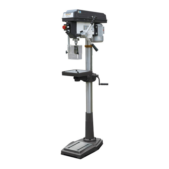
OPTIdrill DQ 25
Operating manual
Optimum OPTIdrill DQ 25 Operating Manual
Hide thumbs
1
Table Of Contents
2
3
4
5
6
7
8
9
10
11
12
13
14
15
16
17
18
19
20
21
22
23
24
25
26
27
28
29
30
31
32
33
34
35
36
37
38
39
40
41
42
43
44
45
46
47
48
49
50
51
52
53
54
55
56
page
of
56
Go
/
56
Contents
Table of Contents
Bookmarks
Table of Contents
Table of Contents
1 Safety
Rating Plates
Safety Instructions (Warning Notes)
Classification of Hazards
Other Pictograms
Intended Use
Reasonably Foreseeable Misuses
Avoiding Misuse
Possible Dangers Posed by the Drilling Machine
Qualification
Target Group Private Users
Obligations of the User
Additional Requirements Regarding the Qualification
User Positions
Safety Measures During Operation
Safety Devices
Personal Protective Equipment
Safety Check
Emergency Stop Switch
1.12.1 Drilling Table
Separating Protective Devices
1.13.1 Drill Chuck Guard
1.13.2 Protective Cover of the V-Belts
1.13.3 Prohibition, Warning and Mandatory Signs
Personal Protective Equipment
Safety During Operation
Safety During Maintenance
1.16.1 Disconnecting and Securing the Drilling Machine
1.16.2 Mechanical Maintenance
Electronics
Inspection Deadlines
2 Technical Specification Emissions
Dimensions DQ25
Dimensions DQ32
3 Delivery, Internal Transport and Commissioning
Notes on Transport, Installation and Commissioning
General Risks During Internal Transport
Delivery
Unpacking
Standard Accessories
Assembly
Installation Requirements
3.5.1 Foundation and Ground
Fixing
First Commissioning
Electrical Connection
Warming up the Machine
4 Operation
Control and Indicating Elements
Control Panel
Switching the Machine on
Switching off the Machine
Drill Depth
Drill Depth Stop
Speed Variation
DQ25 Spindle Speeds
DQ32 Spindle Speeds
Before Starting Work
During Work
Spindle Sleeve Feed
Disassembly, Assembly of Drill Chucks and Drill Bits
4.11.1 Fitting the Drill Chuck
Cooling
5 Determining the Cutting Speed and the Speed
Speed Table
Examples to Calculatory Determine the Required Speed for Your Drilling Machine
6 Maintenance
Safety
Preparation
Restarting
Inspection and Maintenance
Repair
Customer Service Technician
7 Ersatzteile - Spare Parts
Ersatzteilbestellung - Ordering Spare Parts
Hotline Ersatzteile - Spare Parts Hotline
Service Hotline
Ersatzteilzeichnungen - Spare Part Drawings
DQ25 / DQ32 Schaltplan - Wiring Diagram DQ25 / DQ32
8 Malfunctions
9 Appendix 9.1 Copyright
9 Appendix
Liability Claims/Warranty
Terminology/Glossary
Advice for Disposal / Options of Reuse
Decommissioning
Disposal of New Device Packaging
Disposal of the Old Device
9.5.4 Disposal of Electrical and Electronic Components
Storage
Change Information Manual
Disposal Via Municipal Collection Facilities
Product Follow-Up
Advertisement
Quick Links
1
Rating Plates
2
Safety Instructions (Warning Notes)
3
Technical Specification Emissions
Download this manual
Operating Manual
Version 1.0.1
Drilling machine
Part no. 3191047
Part no. 3191049
DQ32
DQ25
Table of
Contents
Previous
Page
Next
Page
1
2
3
4
5
Advertisement
Table of Contents
Need help?
Do you have a question about the OPTIdrill DQ 25 and is the answer not in the manual?
Ask a question
Questions and answers
Related Manuals for Optimum OPTIdrill DQ 25
Drill Optimum OPTIdrill DQ 32 Operating Manual
(56 pages)
Drill Optimum OptiDrill DQ 14 Operating Manual
Bench drill (64 pages)
Drill Optimum OPTidrill DQ 14 Operating Manual
Bench drill (112 pages)
Drill Optimum OPTI drill DQ 20V Operating Manual
Bench drill (82 pages)
Drill Optimum OPTidrill DH 28GSV Operating Manual
Geared drill (116 pages)
Drill Optimum OPTidrill DH 32GSV Operating Manual
Geared drill (116 pages)
Drill Optimum OPTi drill DX 13V Operating Manual
Bench drilling machine (36 pages)
Drill Optimum DX17V Operating Manual
Bench drill (38 pages)
Drill Optimum OPTi drill DX 17V Operating Manual
Bench drill (74 pages)
Drill Optimum Optidrill DM35 Operating Manual
Magnetic drill (74 pages)
Drill Optimum OPTIdrill DM35 Operating Manual
Magnetic drill (86 pages)
Drill Optimum OPTIdrill DP 26 Operating Instructions Manual
(46 pages)
Drill Optimum OPTIdrill DP 33 Operating Manual
(44 pages)
Drill Optimum OPTIdrill D17 Pro Operating Manual
(136 pages)
Drill Optimum OPTI drill DH 26GT Operating Manual
Geared drill (172 pages)
Drill Optimum OPTIdrill DH 35V Operating Manual
Geared drill (84 pages)
This manual is also suitable for:
Optidrill dq 32
3191047
3191049
Table of Contents
Print
Rename the bookmark
Delete bookmark?
Delete from my manuals?
Login
Sign In
OR
Sign in with Facebook
Sign in with Google
Upload manual
Upload from disk
Upload from URL


Need help?
Do you have a question about the OPTIdrill DQ 25 and is the answer not in the manual?
Questions and answers