
Related Manuals for enorossi EASY RAKE Series


Summary of Contents for enorossi EASY RAKE Series
-
Page 1: User And Maintenance Manual
Important: Read all the operating and maintenance instructions in this manual before assembly (EC Machinery Directive 98/37) USER AND MAINTENANCE MANUAL Assembly instructions rev 0 – 02/12... -
Page 2: Harmonised Standards
INDEX... -
Page 3: Table Of Contents
USER AND MAINTENANCE MANUAL..........1 Harmonised standards................2 INTRODUCTION....................4 A1 A .................... 4 BOUT HAY RAKES A2 A ..................4 BOUT THE MANUAL A3 W ...................... 4 ARRANTY A4 EC ............. 5 CERTIFICATION AND IDENTIFICATION A5 M ......... 6 AIN COMPONENTS AND TECHNICAL SPECIFICATIONS SAFETY......................7 B1 G .................. -
Page 4: Introduction
Italian. A2 About the manual The ENOROSSI firm (the “Manufacturer”) designed and created the device in accordance with the relative safety standards to ensure the safety of Symbols used in this manual: personnel and the entire operating system. -
Page 5: A4 Ec Certification And Identification
User and maintenance manual The Customer, upon receipt of the shipment, must check the entire ENOAGRICOLA ROSSI s.r.l. structure for any signs of damage and that the components are intact and CALZOLARO DI UMBERTIDE - PERUGIA - none are missing. Any claims must be made to the Manufacturer in writing within 8 (eight) days of receiving the rake. -
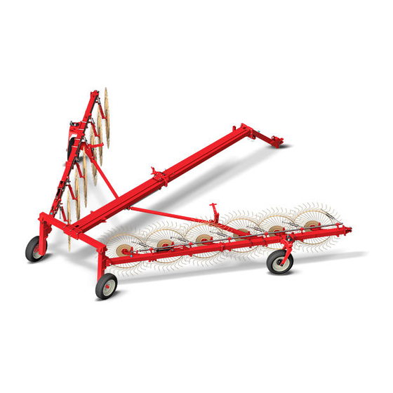
Page 6: A5 Main Components And Technical Specifications
User and maintenance manual A5 Main components and technical specifications 1. Mechanical end stop (to adjust the rake wheel to the ground) 2. Shock absorbing spring 3. Rear wheel 4. Rake wheel 5. Frame 6. Hydraulic quick couplings 7. Supporting foot 8. -
Page 7: Safety
User and maintenance manual manutenzione SAFETY WARNING Loading and unloading must always be carried out with all due B1 General regulations precautions as they can entail a certain element of risk. This manual describes the safety regulations to be followed when using the rake. - Page 8 User and maintenance manual IMPORTANT You must remember that the transportation configuration entails closing the side arms and fitting the equipment with the following The tractor must also, by law, be fitted with a protective roll-bar or safety devices: ROPS or FOPS cabin. It is strictly forbidden to install the rake device on a tractor without the required protection.
-
Page 9: B3 Operator's Responsibilities And Safety
User and maintenance manual B3 Operator's responsibilities and safety Use: the rake must only be put to the use for which it was intended: to Safety is of primary importance to personnel operating the rake device and rake up cut forage. Any other use is therefore improper and forbidden. therefore each operator is directly responsible for controlling the rake's The rake's technical characteristics must also not be altered in any way to operation, maintenance, repairs and/or use of spare parts or consumable... - Page 10 User and maintenance manual IMPORTANT Warning labels and pictograms must be replaced if they become faded and risk becoming illegible. In this case, the operator must not use the rake until any faded labels are replaced with new ones. It is also strictly forbidden to remove the pictograms and labels from the equipment.
-
Page 11: Installation
User and maintenance manual INSTALLATION When the tractor is near the rake's attachment (type 1 or 2 – see picture), the operator turns the lever on the foot support (2) to lift or lower the rake's C1 Rake assembly attachment and insert it in the tractor's attachment. The operator can then As mentioned above, the equipment is fully dismantled for delivery to the insert the locking pin (3) through the attachment holes, as illustrated below, Customer. -
Page 12: C4 Removal
User and maintenance manual illustrated) to their corresponding attachments on the tractor's auxiliary circuits. C4 Removal To remove the rake from the tractor, follow the above instructions in reverse order. The hydraulic connections have to be removed before the actual rake. C5 Storing the rake The Customer must set aside a large and easily accessible area on his premises where the rake can be stored. -
Page 13: 13 - Operation And Use
User and maintenance manual manutenzione • OPERATION and USE Firstly, the operator must remove any safety devices that need to be removed for transportation, i.e. The jacks' end stop devices (B) and the arms' tie rods (A): ∆1 ∆1 ∆1 ∆1 Preliminary information Suitable and optimal use of the rake not only helps avoid accidents but is... - Page 14 A set of additional CONTROL B rake wheels can be supplied with the Easy Rake series (the set, shown in the illustration, is called Kicker wheel and is available on request).
- Page 15 User and maintenance manual Kicker wheel Figure 1 Figure 2 Kicker wheel adjustment After installing the kicker wheel (assembly instructions on page 40), the Prior to work breaks (even short ones) the operator must always: • rake wheels can be better adapted to the ground by adjusting their Switch off the tractor’s engine •...
-
Page 16: Maintenance
User and maintenance manual MAINTENANCE E2 Scheduled maintenance Scheduled maintenance is purely informative and depends on normal operating conditions. It may therefore differ in relation to the type of E1 Maintenance instructions service, working environment (which may be dusty), the season, etc. The Manufacturer has drawn up a rake maintenance schedule based on Maintenance should be stepped up the tougher the machine’s operating functional tests. -
Page 17: E3 Lubrication
User and maintenance manual E3 Lubrication PUNTI DA The jacks move even To top up the greasers, remove their protection caps (if Jack seals are worn Replace seals LUBRIFICARE when the command present), remove all traces of dust and then use the isn’t given pump to inject the grease. - Page 18 User and maintenance manual Machine assembly instructions Assembly 1 For easy-RAKE 8-10-12 A) Connect the horizontal strut (Pos. 1) with the rear suspension bar (Pos. 2) using the six M20x180 T.E. screws at pos. 4 and M.20 self-locking nuts at pos. 5. B) Connect the central suspension bar (Pos.
- Page 19 User and maintenance manual Assembly 1-A For easy-RAKE 14 A) Connect the horizontal strut (Pos. 1) with the rear suspension bar (Pos. 2) using the six M20x180 T.E. screws at pos. 4 and M.20 self-locking nuts at pos. 5. B) Connect the additional central suspension bar (Pos. 6) with the rear suspension bar (Pos.
-
Page 20: Assembly Instructions
User and maintenance manual Assembly 2 For easy-RAKE 8-10-12-14 A) Connect the front suspension bar (Pos. 7) to the central suspension bar: Pos. 6 (mod. EASY-RAKE 12) Pos. 6-A (mod. EASY-RAKE 10) Pos. 6-B (mod. EASY-RAKE 8) Pos. 8 Page 19 assembly 1-A (mod. EASY-RAKE 14) Use the six T.E. - Page 21 User and maintenance manual Assembly 3 For easy-RAKE 8-10-12-14 A) Install the pivot for the right-hand and left-hand frame (pos. 10) in the right-hand and left-hand legs (pos. 16 and 17), placing the AS 5070 anti-seizure coupling (Pos. 11) under the bushing of the pivot and above the leg’s lower bracket.
- Page 22 User and maintenance manual Assembly 4 For easy-RAKE 8-10-12-14 A) Using a forklift truck, lift the horizontal strut already connected to the rear, central and front suspension bars; the front suspension bar should be left resting on the ground. Make sure the structure remains perfectly stable.
- Page 23 User and maintenance manual Assembly 5 For easy-RAKE 8-10-12 DETAIL A 41 A A) Install the two rear left-hand and right-hand frames (pos. 29), connecting them to the two legs with the Ø50x225 pivot pins (pos. 30 – see detail A). Connect the Ø50 pin (pos. 30) with the M8x80 T.E. screw (pos. 31) and M8 self-locking nut (pos. 32). Install the two M8x1 greasers (pos.
- Page 24 User and maintenance manual Assembly 5/A For easy-RAKE 14 Follow the instructions at points A-B-C for assembly 5. Next: D) Install the additional front right and left-hand parts of the frame (pos. 41), connecting them to the front frame (pos. 34) with 16x45 T.E. screws (pos. 35) and M16 self-locking nuts (pos. 36). E) Install the front right and left wheel-supports (pos.
- Page 25 User and maintenance manual Assembly 6 For easy-RAKE 8-10-12 A) Insert the AS 50-70 coupling (pos. 48) on the Ø50 pin (pos. 47) of the pivoting wheel. B) Install the two wheels with pivoting fork (pos. 47) on the support (pos. 37). C) Install the disk brake (pos.
- Page 26 User and maintenance manual Assembly 6/A For easy-RAKE 14 A) Insert the AS 50-70 coupling (pos. 48) on the Ø50 pin (pos. 47) of the pivoting wheel. B) Connect the two wheels with pivoting fork (pos. 47) to the front wheel support (pos.
- Page 27 User and maintenance manual Assembly 7- 8 For easy-RAKE 8-10-12-14 A) Fit the two unions – left and right (pos. 57) – on the two front frames, at the centre of the two vertical rabbets on the inner side of the front frames. Connect the unions with the fixing plates (pos. 58), M20x180 T.E. screws (pos.
- Page 28 User and maintenance manual Assembly 9 For easy-RAKE 8-10-12 -14 A) Install the hydraulic cylinder (pos. 61) and connect it to the Ø30x100 pin (pos. 62). Insert the hydraulic cylinder’s rod in the pin slide; connect with Ø27 washer (pos. 64) and Ø8x50 elastic pin (pos. 65). ASSEMBLY - 28 rev.0 –...
- Page 29 User and maintenance manual Assembly 10 For easy-RAKE 8-10-12 -14 A) Install the connecting rod (pos. 66) and connect it to the union with the Ø30x175 pin (pos. 67) and 10x60 elastic pins (pos. 68). Fix the connecting rod to the slide with Ø30x135 pin (pos.
- Page 30 User and maintenance manual Assembly 11 For easy-RAKE 8-10-12 -14 Star movement bars assembly: A) Assemble the hydraulic cylinder Pos. 79 and fix it in the frame with the pin Ø25x62 Pos. 80. Fix pin Ø25x62 Pos. 80 with spring pins Ø5x100 Pos.
- Page 31 User and maintenance manual Assembly 12 For easy-RAKE 14 75/B MOD.8 75/A MOD.10 MOD.12 MOD.14 A) Install the central bar (Pos. 75) and use the Ø34x80 bushing (Pos. 76) to connect it to the front rake wheel bar (Pos. 79). Connect with M8x50 T.E.
- Page 32 User and maintenance manual Assembly 14 For easy-RAKE 8-10-12 -14 A) Install the right and left arms (pos. 85), connecting with Ø31x56 washers (Pos. 86) and Ø6x50 elastic pin (Pos. 88). N.B: the last arm, right and left, is to be blocked with the Ø8 linch pin (Pos. 87), to ensure easy removal of the two arms for adjusting swath width.
- Page 33 User and maintenance manual Assembly 15 For easy-RAKE 8-10-12 -14 A) Install the Ø50x200 springs (pos. 91), passing through the chain (twenty-one 38x23 rings) (pos. 90). B) The first ring on the chain is to be attached to the arm’s bracket with the M10x30 T.E. screw (pos.
- Page 34 User and maintenance manual Assembly 16 For easy-RAKE 8-10-12 -14 Installation of the hydraulic fittings: A) Connect the Ø5/16 Lg. 1600 rubber hydraulic pipe (pos. 97) (for mod. EASY-RAKE 8-10- 12) or the Ø5/16 Lg. 2510 rubber hydraulic pipe (pos. 97 (for mod. EASY-RAKE 14), to the hydraulic pipe: Pos.
- Page 35 User and maintenance manual Assembly 17 For easy-RAKE 8-10-12 -14 A) Install the right-hand rake wheels (pos. 109) and the left-hand ones. Connect them to the hub of the arm with M10x25 T.E. screws (pos. 110) and M10 self-locking nuts (pos. 111).
- Page 36 User and maintenance manual Assembly 18 For easy-RAKE 8-10-12 Installation of the transport bars A) Connect the two transport bars (pos. 112), to the two side frames and to the central suspension bar with the Ø25x100 pins (pos. 113). ASSEMBLY - 36 rev.0 –...
- Page 37 User and maintenance manual Assembly 18 For easy-RAKE 14 Installation of the transport bars A) Connect the two transport bars (pos. 112) to the two front wheel supports and the central suspension bar, using the Ø25x100 pins (pos. 113). ASSEMBLY - 37 rev.0 –...
- Page 38 User and maintenance manual Assembly of central rake wheels (optional) central rake wheel assembly (optional) A) Connect the fixed frame (pos. 1) to the front suspension bar (pos. 29), attach the 174x240x10 plate (pos. 2), M16x160 T.E. screws (pos. 3) and M16 self-locking nuts (pos.
- Page 39 User and maintenance manual central rake wheel assembly (optional) A) Install the ½ GAS 3-way male joint (pos. 1) in the 5/16 LG: 550 mm hydraulic pipe (pos. 2). B) Insert the pipe (pos. 2) between the Ø5/16 LG. 1600 pipe (pos. 5) and the Ø5/16 pipe (pos.
- Page 40 User and maintenance manual ASSEMBLY - 40 rev.0 – 02/12...
-
Page 41: Spare Parts
ENOAGRICOLA ROSSI srl - Calzolaro di Umbertide - Perugia - Italy Tel. 075 / 930 22 22 Telefax 075 / 930 23 28 enorossi@enorossi.it - Info@enorossi.it http://www.enorossi.it - www.enoagricolarossi.it - www.enoagricolarossi.com To ensure prompt assistance and replacement of parts always supply below required information, thank you. Company name Invoice address... - Page 42 User and maintenance manual TABLE 1 – cod.19010506 EASY RAKE 8-10-12-14 ASSEMBLY - 42 rev.0 – 02/12...
- Page 43 user and maintenance manual TABLE 1 - cod. 19010506 EASY RAKE 8-10-12-14 POS. CODE DESCRIPTION 18032711 LEFT REAR FRAME E.R. 8-10-12-14 3080102 SPRING PIN 6X36 18031179 REGOLATION KNOB 3020337 NUT 24MA 3020202 SELF LOCKING NUT 12MA 18032113 LEFT BAR PASSAGE BRACKET 3011216 SCREW TW M12X35 SPRING PIN 6X50...
- Page 44 User and maintenance manual TABLE 2 – cod. 19010507 EASY RAKE 8-10-12-14 ER14 ER12-14 ER10 SPARE PARTS - 44 rev.0 – 02/12...
- Page 45 User and maintenance manual TABLE 2 – cod. 19010507 EASY RAKE 8-10-12-14 POS. CODE DESCRIPTION 18032022 FASTENING PLATE 3020216 SELF LOCKING NUT 20MA 3011648 SCREW TE 20X180 18032023 PULL BAR E.R. 8-10-12-14 18032024 CONNECTING BAR 3011694 SCREW TE M20X55 18032025 CENTRAL DRAWBAR E.R.
- Page 46 User and maintenance manual TABLE 3 – cod. 19010508 EASY RAKE 8-10-12 SPARE PARTS - 46 rev.0 – 02/12...
- Page 47 User and maintenance manual TABLE 3 – cod. 19010508 EASY RAKE 8-10-12 POS. CODE DESCRIPTION 3020204 SELF LOCKING NUT 16MA 3011645 SCREW TE M16X45 18032030 LEFT FRONT FRAME ER 8 18032031 LEFT FRONT FRAME ER 10 18032062 LEFT FRONT FRAME ER 12-14 3011210 SCREW TE M8X50 18030435...
- Page 48 User and maintenance manual TABLE 3/A - cod. 19010519 EASY RAKE 14 29 29 10 31 SPARE PARTS - 48 rev.0 – 02/12...
- Page 49 User and maintenance manual TABLE 3/A – cod. 19010519 EASY RAKE 14 POS. CODE DESCRIPTION 3020204 SELF LOCKING NUT 16MA 3011645 SCREW TE M16X45 18032030 LEFT FRONT FRAME ER 12-14 3011210 SCREW TE M8X50 18030435 BUSH D.33,7 LG.80 3020209 SELF LOCKING NUT 8MA 18032033 ELBOW ARM ATTACHMENT BRACKETS SCREW TE M20X180...
- Page 50 User and maintenance manual cod. 19010509 EASY RAKE 8-10-12-14 TABLE 4 - 12-12A-12B SPARE PARTS - 50 rev.0 – 02/12...
- Page 51 User and maintenance manual TABLE 4 – cod. 19010509 EASY RAKE 8-10-12-14 POS. CODE DESCRIPTION 18032065 CROSS DRAWBAR 3011694 SCREW TE M20X55 3020216 SELF LOCKING NUT 20MA 18032048 LEFT WHEEL LEG SUPPORT 3011695 SCREW TE M8X80 12170108 COMPLETE WHEEL 205/70 R15 18032049 PIVOTING SUPPORT PIN D.50 LG.295...
- Page 52 User and maintenance manual TABLE 5 - cod. 19010510 EASY RAKE 8-10-12-14 SPARE PARTS - 52 rev.0 – 02/12...
- Page 53 User and maintenance manual TABLE 5 - cod. 19010510 EASY RAKE 8-10-12-14 POS. CODE DESCRIPTION 18032020 COMPLETE RIGHT ARM 18032019 COMPLETE LEFT ARM 12860001 DUST COVER 25X52 12240119 BEARING 30205 3020328 NUT 10MA 3030227 LOCK WASHER M10 12150103 SCREW TE 10X25 3010261 GREASE ZERK 8MB 3090101...
- Page 54 User and maintenance manual TABLE 6 - cod. 19010511 EASY RAKE 8-10-12-14 7 8 9 SPARE PARTS - 54 rev.0 – 02/12...
- Page 55 User and maintenance manual TABLE 6 – cod. 19010511 EASY RAKE 8-10-12-14 POS. CODE DESCRIPTION 18031737 WHEEL SUPPORT 3080117 SPRING PIN 10X70 18032051 BRAKING DISC 12070440 NYLON BUSH 505560 3090101 GREASE ZERK 8MB 12280007 SPACER AS 5070 3020201 SELF LOCKING NUT 10MA NUT 30MB 3020219 ROLL PIN 6X60...
- Page 56 User and maintenance manual TABLE 7 - cod. 19010512 EASY RAKE 8-10-12-14 SPARE PARTS - 56 rev.0 – 02/12...
- Page 57 User and maintenance manual TABLE 7 – cod. 19010512 EASY RAKE 8-10-12-14 POS. CODE DESCRIPTION 12360003 DUST COVER CAP 3020217 SELF LOCKING NUT 20MB 12240119 BEARING 30205 3020218 STUD BOLT 16MB 12150108 3011609 STUD BOLT M16 12240143 BEARING 30207 DUST COVER 35X72 12360002 SPRING PIN 4X35 3040114...
- Page 58 User and maintenance manual TABLE 8 - cod. 19010513 EASY RAKE 8-10-12-14 14 11 15 11 14 SPARE PARTS - 58 rev.0 – 02/12...
- Page 59 User and maintenance manual TABLE 8 – cod. 19010513 EASY RAKE 8-10-12-14 POS. CODE DESCRIPTION 12770135 CYLINDER 3020217 SELF LOCKING NUT 20MB 12770216 PISTON 0706020 SELA DBM 236173 O-RING 8-125 O-RING 8-156 12420104 GUIDE BALSELE SCRAPER RING WRM 118149 12440102 SHAFT D.35 3030403 COPPER WASHER 3/8...
- Page 60 User and maintenance manual TABLE 9 - cod. 19010514 EASY RAKE 8-10-12-14 SPARE PARTS - 60 rev.0 – 02/12...
- Page 61 User and maintenance manual TABLE 9 – cod. 19010514 EASY RAKE 8-10-12-14 POS. CODE DESCRIPTION 12770103 CYLINDER 3020215 SELF LOCKING NUT 14MB 12770104 PISTON 0704015 GASKET DBM 157118 O-RING 616 O-RING 219 12420101 GUIDE BALSELE SCRAPER RING WRM 118149 12440101 SHAFT 10010636 SEAL KIT FOR CYLINDER 12770101...
- Page 62 User and maintenance manual TABLE 10 - cod. 19010515 EASY RAKE 8-10-12-14 DETTAGLIO A 13 14 DETTAGLIO B SPARE PARTS - 62 rev.0 – 02/12...
- Page 63 User and maintenance manual TABLE 10 – cod. 19010515 EASY RAKE 8-10-12-14 POS. CODE DESCRIPTION 4010915 “T” UNION ½” 12760212 HYDRAULIC HOSE LG.2500 ER 8-10-12-14 12980005 COLLAR C3 3010637 SCREW M6X28 UNI 5931 3011605 DRILLED SCREW 3/8” 3030403 COPPER WASHER 17X23X1,5 12760205 HYDRAULIC HOSE LG.
- Page 64 User and maintenance manual TABLE 11 - cod. 19010516 (OPTIONAL) SPARE PARTS - 64 rev.0 – 02/12...
- Page 65 User and maintenance manual TABLE 11 – cod. 19010516 POS. CODE DESCRIPTION 18032047 MAIN FRAME 1013197 FASTENING PLATE 3010309 SCREW TE M16X160 3020204 SELF LOCKING NUT 16MA 18032052 SWIVELLING FRAME 12060883 PIN D. 30 LG. 190 3010781 SCREW TE M8X55 NUT 8MA 3020329 PIN 16X213...
- Page 66 User and maintenance manual TABLE 11/A - cod. 19010518 EASY RAKE 8-10-12-14 (OPTIONAL) SPARE PARTS - 66 rev.0 – 02/12...
- Page 67 User and maintenance manual TABLE 11/A – cod. 19010518 EASY RAKE 8-10-12-14 POS. CODE DESCRIPTION 18032068 SHAFT ATTACHMENT 3020336 NUT M20 18032069 SHAFT 18032070 SHAFT HEAD 18032071 WASHER 11010627 SPRING 18032072 CYLINDER SPARE PARTS - 67 rev.0 – 02/12...
- Page 68 User and maintenance manual TABLE 12 cod. 19010517 EASY RAKE 8-10-12-14 (OPTIONAL) SPARE PARTS - 68 rev.0 – 02/12...
- Page 69 User and maintenance manual TABLE 12 – cod. 19010517 EASY RAKE 8-10-12-14 POS. CODE DESCRIPTION 18032053 FRAME 12860001 DUST COVER 12240119 BEARING 30205 12150103 12240118 BEARING 30204 3090101 GREASE ZERK 8MB 3020210 SELF LOCKING NUT 18MB DUST COVER CUP 12360001 SPRING 4X35 3040114 3010105...
- Page 70 User and maintenance manual Table 13 – Cod. 19010555 EASY RAKE 10-12-14-16-18-20 (type-approval) 7 8 11 SPARE PARTS - 70 rev.0 – 02/12...
- Page 71 User and maintenance manual Table 13 – Cod. 19010555 EASY RAKE 10-12-14-16-18-20 (type-approval) POS. CODICE Description Descrizione 7270009 Complete light kit for type-approval ER 10 mt. 11 Kit luci completo per omologazione ER 10 mt. 11 7270008 Complete light kit for type-approval ER 12 mt. 12 Kit luci completo per omologazione ER 12 mt.
- Page 72 User and maintenance manual Table 14 – Cod. 19010556 EASY RAKE 8-10-12-14 AUTOSTEER SPARE PARTS - 72 rev.0 – 02/12...
- Page 73 User and maintenance manual Table 14 – Cod. 19010556 Per EASY RAKE 8-10-12-14 AUTOSTERZANTE POS. CODICE DESCRIPTION 7270001 Complete light kit electrical cable along mt. 10 ER 10 7270002 Complete light kit electrical cable along mt. 11 ER 12 7270003 Complete light kit electrical cable along mt.
- Page 74 User and maintenance manual ENOAGRICOLA ROSSI s.r.l. 06010 Calzolaro di Umbertide Perugia Italia Tel. (39) 075-930 22 22 - Telefax (39) 075-930 23 28 e-mail: enorossi@enorossi.it – info@enorossi.it web: http://www.enorossi.it - http://www.enoagricolarossi.com SPARE PARTS - 74 rev.0 – 02/12...
Need help?
Do you have a question about the EASY RAKE Series and is the answer not in the manual?
Questions and answers