
Related Manuals for Agilent Technologies 83400 Series


Summary of Contents for Agilent Technologies 83400 Series
- Page 1 sales@artisantg.com artisantg.com (217) 352-9330 | Click HERE Find the Keysight / Agilent 83400-60005 at our website:...
- Page 2 Agilent 83400-Series Lightwave Source and Receiver Modules User’s Guide...
- Page 3 Agency. country. The information contained in WARNING this document is subject to This text denotes the Agilent Technologies war- ISM1-A change without notice. Com- The warning sign denotes a instrument is an rants that its software and panies, names, and data used hazard.
-
Page 4: The Agilent 83400-Series-At A Glance
The Agilent 83400-Series—At a Glance The Agilent 83400-Series—At a Glance Agilent 83400-series sources The Agilent 83400-series sources can be amplitude modulated by an external RF source. They can be modulated with up to +14 dBm (about 25 mW) of RF power. -
Page 5: Laser Classification
W A R N I N G Do not enable the laser when no fiber or equivalent device is attached to the OPTICAL OUTPUT connector. These products cannot be serviced. If service is required, return the instru- ment to Agilent Technologies. - Page 6 Laser Classification IEC and FDA labels (and their placement) on an Agilent 83402C...
- Page 7 General Safety Considerations General Safety Considerations This product has been designed and tested in accordance with IEC Publica- tion 61010-1, Safety Requirements for Electrical Equipment for Measurement, Control, and Laboratory Use, and has been supplied in a safe condition. The instruction documentation contains information and warnings that must be followed by the user to ensure safe operation and to maintain the product in a safe condition.
- Page 8 General Safety Considerations C A U T I O N Before switching on this instrument, make sure that the line voltage selector switch is set to the line voltage of the power supply and the correct fuse is installed. Assure the supply voltage is in the specified range. C A U T I O N This product is designed for use in Installation Category II and Pollution Degree 2 per IEC 1010 and 664 respectively.
-
Page 10: Table Of Contents
Calibration Data Information 2-7 Cleaning Connections for Accurate Measurements 2-11 Theory of Operation 2-21 Returning the Instrument for Service 2-25 Agilent Technologies Service Offices 2-28 3 Specifications and Regulatory Information Specifications for Sources 3-3 Specifications for Receivers 3-7 Operating Specifications for Sources and Receivers 3-13... - Page 12 Inspecting the Shipment 1-4 Connecting a Source 1-5 If you encounter a problem 1-7 Connecting a Receiver 1-8 Entering Calibration Data into an Agilent 8702D 1-9 To copy the data from the disk 1-10 To manually enter data from the label 1-10 Entering Calibration Data into an Agilent 8702A/B 1-11 To install from the front panel 1-11 To install from an external disk drive 1-12...
-
Page 13: Getting Started
Getting Started Getting Started Getting Started The instructions in this chapter show you how to install your Agilent 83400- series source or receiver module. Because these products are key accessories for the Agilent 8702-series lightwave component analyzers, this book empha- sizes installation into the Agilent 8702D. - Page 14 Getting Started Getting Started C A U T I O N Exposing the Agilent 83400-series source or receiver module to temperatures above 55°C may cause the optical fiber in the front-panel connector to shrink and retract. C A U T I O N This product is designed for use in INSTALLATION CATEGORY II and POLLUTION DEGREE 2, per IEC 601010 and 60664 respectively.
-
Page 15: Inspecting The Shipment
Inspect all shipping containers. If your shipment is damaged or incomplete, save the packing materials and notify both the shipping carrier and the nearest Agilent Technologies sales and service office. Agilent Technologies will arrange for repair or replacement of damaged or incomplete shipments without waiting for a settlement from the transportation company. -
Page 16: Connecting A Source
Getting Started Connecting a Source Connecting a Source 1 For Agilent 83402C products, perform the following two steps: a If you are located outside of the United States or Canada, locate the yellow sheet of IEC laser classification and laser safety labels supplied with the source. - Page 17 Getting Started Connecting a Source Figure 1-2. Location of laser safety labels...
-
Page 18: If You Encounter A Problem
• The remote shutdown is open. • The power supply voltage(s) are out of spec (–12.6 V ±5% and +15 V ±5%). • There is an internal malfunction of the unit; contact Agilent Technologies for assistance. These products cannot be serviced. If service is required, return the instru-... -
Page 19: Connecting A Receiver
Getting Started Connecting a Receiver Connecting a Receiver 1 Connect the DC cable, supplied with the receiver, between the receiver’s rear- panel DC IN connector and a PROBE POWER jack. You’ll find PROBE POWER jacks on the following products: • Agilent 8702A/B/D lightwave component analyzer •... -
Page 20: Entering Calibration Data Into An Agilent 8702D
Getting Started Entering Calibration Data into an Agilent 8702D Entering Calibration Data into an Agilent 8702D Agilent 83400-series lightwave sources and receivers have calibration data which must be entered into the Agilent 8702. The data is supplied on a disk and printed on a label. -
Page 21: To Copy The Data From The Disk
Getting Started Entering Calibration Data into an Agilent 8702D To copy the data from the disk The following procedure is written specifically for entering source data. If you are entering data for a receiver, simply substitute the word RECEIVER for SOURCE and the word RCVR for SRC. -
Page 22: Entering Calibration Data Into An Agilent 8702A/B
Getting Started Entering Calibration Data into an Agilent 8702A/B Entering Calibration Data into an Agilent 8702A/B Before using your source or receiver with an Agilent 8702A/B lightwave com- ponent analyzer, you must load the calibration data as described in this sec- tion. -
Page 23: To Install From An External Disk Drive
Getting Started Entering Calibration Data into an Agilent 8702A/B To install from an external disk drive If you have an HP 9122-series dual-sided disk drive connected to your Agilent 8702A/B, use this procedure to enter the source or receiver’s calibra- tion data. - Page 24 Operating 2-2 Replaceable Parts 2-5 Calibration Data Information 2-7 Cleaning Connections for Accurate Measurements 2-11 Theory of Operation 2-21 Returning the Instrument for Service 2-25 Agilent Technologies Service Offices 2-28 General Information...
-
Page 25: General Information Operating
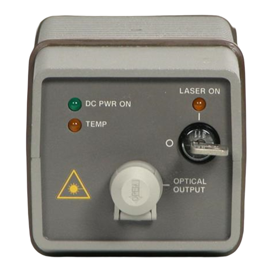
General Information Operating Operating Laser sources Front and rear panel features The DC POWER ON light turns on whenever DC power is supplied. The front-panel OPTICAL OUTPUT connector has a special adapter which allows you to easily change the front-panel connector to one of many standard inter- faces. - Page 26 General Information Operating Figure 2-1. Front and rear panels on a source When the key is turned on, the laser is turned on and the front-panel LASER ON light turns on. However, the rear-panel REMOTE SHUTDOWN BNC connector must be shorted for the laser to operate. When the BNC short is removed from the connector, the accessible radiation does not exceed the AEL for FDA LASER Class IIIb (IEC LASER Class 3B) for the Agilent 83402C and FDA LASER Class I (IEC LASER Class 1) for the Agilent 83403C according to IEC...
- Page 27 General Information Operating Receivers Figure 2-2. Front and rear panels on a receiver Front and rear panel features While the DC IN connector provides a connection to power the receiver, the DC OUT connector can be used to power to another source or receiver. The front-panel OPTICAL INPUT connector has a special adapter which allows you to easily change the front-panel connector to one of many standard inter- faces.
-
Page 28: Replaceable Parts
BNC short (m) for rear-panel REMOTE SHUTDOWN connector (sources) 1250-0774 One OPTICAL OUTPUT adapter must be ordered with the instrument. These adapters are ordered as Option 011, 012, 013, 014, 015, or 017. These adapters with their Agilent Technologies model numbers are shown in the following fig- ure. -
Page 29: Front-Panel Optical Adapters
General Information Front-Panel Optical Adapters Front-Panel Optical Adapters Front Panel Fiber-Optic Description Agilent Part Number Adapter Diamond HMS-10 81000AI 81000FI FC/PC 81000GI 81000KI 81000SI 81000VI Biconic 81000WI Dust Covers FC connector 1005-0594 Diamond HMS-10 connector 1005-0593 DIN connector 1005-0595 ST connector 1005-0596 SC connector 1005-0597... -
Page 30: Calibration Data Information
Although the Agilent 83400-series source and receiver modules are designed to be stable, they can be returned to the factory for recharacterization (cali- bration) at a desired time for a reasonable fee. Agilent Technologies recom- mends that recharacterization be done at approximately one year intervals. - Page 31 General Information Calibration Data Information Making a backup disk Hewlett-Packard recommends that you make a backup or extra copy of the disk data, label it properly, and make sure it is only used with the source or receiver that its data describes. If you need to make a backup copy of a LIF-formatted disk, you must have an HP controller (computer).
- Page 32 General Information Calibration Data Information Interpreting filenames Each digit in a filename has a specific meaning. For example, consider the number S2300045. The digits, from left to right, have the following definitions: Digit Description S indicates single-mode fiber. M indicates multimode fiber.
- Page 33 General Information Calibration Data Information In the Agilent 8702D, these coefficients are applied to the following equation: -jωB ) C jω D jω E jω responsivity (ω ) ------------------------------------------------------------------------------------------------- - F jω G jω H jω I jω ω where, , and e represents the base of the natural 2π...
-
Page 34: Cleaning Connections For Accurate Measurements
Connectors also vary in the polish, curve, and concentricity of the core within the cladding. Mating one style of cable to another requires an adapter. Agilent Technologies offers adapters for most instruments to allow testing with many different cables. - Page 35 General Information Cleaning Connections for Accurate Measurements tions take repeatability uncertainty into account? • Will a connector degrade the return loss too much, or will a fusion splice be re- quired? For example, many DFB lasers cannot operate with reflections from connectors.
- Page 36 0.2 µm. This process, plus the keyed axis, allows very precise core-to-core alignments. This connector is found on most Agilent Technologies lightwave instruments. 2-13...
- Page 37 General Information Cleaning Connections for Accurate Measurements The soft core, while allowing precise centering, is also the chief liability of the connector. The soft material is easily damaged. Care must be taken to mini- mize excessive scratching and wear. While minor wear is not a problem if the glass face is not affected, scratches or grit can cause the glass fiber to move out of alignment.
- Page 38 General Information Cleaning Connections for Accurate Measurements Use the following guidelines to achieve the best possible performance when making measurements on a fiber-optic system: • Never use metal or sharp objects to clean a connector and never scrape the connector. •...
- Page 39 General Information Cleaning Connections for Accurate Measurements Figure 2-9. Damage from improper cleaning. While these often work well on first insertion, they are great dirt magnets. The oil or gel grabs and holds grit that is then ground into the end of the fiber. Also, some early gels were designed for use with the FC, non-contacting con- nectors, using small glass spheres.
- Page 40 General Information Cleaning Connections for Accurate Measurements • Keep connectors covered when not in use. • Use fusion splices on the more permanent critical nodes. Choose the best con- nector possible. Replace connecting cables regularly. Frequently measure the return loss of the connector to check for degradation, and clean every connec- tor, every time.
- Page 41 Cleaning Connectors The procedures in this section provide the proper steps for cleaning fiber- optic cables and Agilent Technologies universal adapters. The initial cleaning, using the alcohol as a solvent, gently removes any grit and oil. If a caked-on layer of material is still present, (this can happen if the beryllium-copper sides of the ferrule retainer get scraped and deposited on the end of the fiber during insertion of the cable), a second cleaning should be performed.
- Page 42 General Information Cleaning Connections for Accurate Measurements Table 2-4. Dust Caps Provided with Lightwave Instruments Item Agilent Part Number Laser shutter cap 08145-64521 FC/PC dust cap 08154-44102 Biconic dust cap 08154-44105 DIN dust cap 5040-9364 HMS10/dust cap 5040-9361 ST dust cap 5040-9366 To clean a non-lensed connector C A U T I O N...
- Page 43 To clean an adapter The fiber-optic input and output connectors on many Agilent Technologies instruments employ a universal adapter such as those shown in the following picture. These adapters allow you to connect the instrument to different types of fiber-optic cables.
-
Page 44: Theory Of Operation
General Information Theory of Operation Theory of Operation Agilent 83402C and Agilent 83403C sources The lightwave sources consist of a laser diode, bias circuitry, and control cir- cuitry. An attenuator and impedance matching network blocks the DC compo- nent from the RF input that modulates the laser light. The laser diode is made from InGaAsP (Indium Gallium Arsenide Phosphide) and has a corresponding back-face diode that is used to control or stabilize the lightwave output. - Page 45 General Information Theory of Operation Figure 2-11. Source block diagram Agilent 83410C, 83411C/D, and 83412B receivers The lightwave receivers consist of an optical input connector and fiber, launch objects, a PIN diode detector, a thin-film hybrid amplifier, and one DC circuit board.
- Page 46 General Information Theory of Operation Active bias circuitry is used in the first amplifier stage to hold its DC bias fixed, while the DC photocurrent from the PIN diode varies. A combination threshold/hysteresis function on the DC board monitors the output of the active bias current and uses the signal to light the OVER ILLUMINATION LED if the average optical input power exceeds 3.5 mW.
- Page 47 General Information Theory of Operation Figure 2-13. Agilent 83410C and 83412B block diagram 2-24...
-
Page 48: Returning The Instrument For Service
Technologies Service Offices” on page 2-28 for a list of service offices. Agilent Technologies Instrument Support Center... (800) 403-0801 If the instrument is still under warranty or is covered by an Agilent Technolo- gies maintenance contract, it will be repaired under the terms of the warranty or contract (the warranty is at the front of this manual). - Page 49 They may also cause instrument damage by generating static electricity. 3 Pack the instrument in the original shipping containers. Original materials are available through any Agilent Technologies office. Or, use the following guidelines: • Wrap the instrument in antistatic plastic to reduce the possibility of damage caused by electrostatic discharge.
- Page 50 General Information Returning the Instrument for Service Sealed Air Corporation (Commerce, California 90001). Air Cap looks like a plastic sheet filled with air bubbles. Use the pink (antistatic) Air Cap™ to reduce static electricity. Wrapping the instrument several times in this ma- terial will protect the instrument and prevent it from moving in the carton.
-
Page 51: Agilent Technologies Service Offices
General Information Agilent Technologies Service Offices Agilent Technologies Service Offices Before returning an instrument for service, call the Agilent Technologies Instrument Support Center at (800) 403-0801, visit the Test and Measurement Web Sites by Country page at http://www.tm.agilent.com/tmo/country/English/ index.html, or call one of the numbers listed below. -
Page 52: Specifications And Regulatory Information
Specifications for Sources 3-3 Specifications for Receivers 3-7 Operating Specifications for Sources and Receivers 3-13 Regulatory Information 3-14 Specifications and Regulatory Information... - Page 53 To maintain specifications, periodic recalibrations are necessary. We recommend that Agilent 83411C/D receivers be calibrated at an Agilent Technologies service facility every 24 months. We recommend that all other sources and receivers be calibrated every 12 months.
-
Page 54: Specifications For Sources
Specifications and Regulatory Information Specifications for Sources Specifications for Sources The following section includes specifications and characteristics of the Agilent 83400-series sources. Specifications and Characteristics for Sources (1 of 2) Specification/Characteristic 83402C 83403C WAVELENGTH 1310 ±30 nm 1550 ±30 nm Center Wavelength 0.3% per year 0.3% per year... - Page 55 Specifications and Regulatory Information Specifications for Sources Specifications and Characteristics for Sources (2 of 2) Specification/Characteristic 83402C 83403C Equivalent Input Noise (characteristics) 0.01 to 5 GHz –124 dBm/Hz –124 dBm/Hz 5 to 6 GHz –119 dBm/Hz –119 dBm/Hz Reflection Sensitivity (characteristics) ±0.04 dBe ±0.04 dBe...
- Page 56 Specifications and Regulatory Information Specifications for Sources Agilent 83402C: Modulation frequency response (characteristic) Agilent 83402C: Electrical input port return loss (characteristic)
- Page 57 Specifications and Regulatory Information Specifications for Sources Agilent 83403C: Modulation frequency response (characteristic) Agilent 83403C: Electrical input port return loss (characteristic)
-
Page 58: Specifications For Receivers
Specifications and Regulatory Information Specifications for Receivers Specifications for Receivers In the following table, demodulation frequency response values are deter- mined as defined by the following equation: linear responsivity 1 dB (A/W) ---------------------------------------------------- 1 (A/W) Specifications and Characteristics for Receivers (1 of 2) Specification/Characteristic 83410C 83411C... - Page 59 Specifications and Regulatory Information Specifications for Receivers Specifications and Characteristics for Receivers (2 of 2) Specification/Characteristic 83410C 83411C 83411D 83412B 300 kHz to 3 GHz 0 to 20 dB Optical Attenuation – – – ± 1.5 dB 0 to 25 dB Optical Attenuation –...
- Page 60 Specifications and Regulatory Information Specifications for Receivers Agilent 83410C: Demodulation frequency response (characteristic) Agilent 83410C: Electrical output port return loss (characteristic)
- Page 61 Specifications and Regulatory Information Specifications for Receivers Agilent 83411C: Demodulation frequency response (characteristic) Agilent 83411C: Electrical output port return loss (characteristic) 3-10...
- Page 62 Specifications and Regulatory Information Specifications for Receivers Agilent 83411D: Demodulation frequency response (characteristic) Agilent 83411D: Electrical output port return loss (characteristic) 3-11...
- Page 63 Specifications and Regulatory Information Specifications for Receivers Agilent 83412B: Demodulation frequency response (characteristic) Agilent 83412B: Electrical output port return loss (characteristic) 3-12...
-
Page 64: Operating Specifications For Sources And Receivers
Specifications and Regulatory Information Operating Specifications for Sources and Receivers Operating Specifications for Sources and Receivers Indoor Voltage (DC power input) –12.6 V ±5% +15 V ±5% Temperature Limits ° ° Operating C to +55 ° ° Non-operating –40 to +55 Maximum relative humidity <... -
Page 65: Regulatory Information
Specifications and Regulatory Information Regulatory Information Regulatory Information • Laser Classification: • The Agilent 83402C is classified as an FDA LASER Class IIIb (IEC LASER Class 3B). • The Agilent 83403C is classified as an FDA LASER Class I (IEC LASER Class •... - Page 66 Specifications and Regulatory Information Regulatory Information Declaration of conformity (sources) 3-15...
- Page 67 Specifications and Regulatory Information Regulatory Information Declaration of conformity (receivers) 3-16...
-
Page 68: Performance Tests
Tests for Sources 4-4 1. Center Wavelength and Spectral Width 4-4 2. Average Output Power 4-5 3. Electrical Input Port Match 4-6 Tests for Receivers 4-7 1. Demodulation Frequency Response 4-7 2. RF Port Match 4-7 3. Dynamic Accuracy 4-8 Performance Tests... - Page 69 To maintain specifications, periodic recalibrations are necessary. We recommend that Agilent 83411C/D receivers be calibrated at an Agilent Technologies service facility every 24 months. We recommend that all other sources and receivers be calibrated every 12 months.
- Page 70 Performance Tests Performance Tests Table 4-1. Required Equipment for Performance Tests Recommended Agilent Instrument Technologies Model Optical Spectrum Analyzer 71450 series • Polarization Controller 11896A • Lightwave Component Analyzer 8702 • • 8702 Option 006 • • APC 7 mm to 3.5 mm Adapter •...
-
Page 71: Tests For Sources
Performance Tests Tests for Sources Tests for Sources 1. Center Wavelength and Spectral Width To perform this test, you need an Agilent 71450A/B-series optical spectrum analyzer. These optical spectrum analyzers come with an advanced measure- ment program which automatically characterizes DFB lasers. Do not modulate the source during this procedure. -
Page 72: Average Output Power
Performance Tests Tests for Sources 5 Compare the measured values to the specified values listed in Chapter 3, “Specifications and Regulatory Information”. 2. Average Output Power Do not modulate the source during this procedure. 1 Connect the equipment as shown in Figure 4-2. -
Page 73: Electrical Input Port Match
Performance Tests Tests for Sources 3. Electrical Input Port Match 1 Connect the equipment as shown in Figure 4-3. Figure 4-3. Electrical input port match test setup 2 Turn on the equipment, and allow them to warm up for 1 hour. 3 Use the Agilent 8702D’s “Guided Setup”... -
Page 74: Tests For Receivers
Performance Tests Tests for Receivers Tests for Receivers 1. Demodulation Frequency Response This performance test requires the use of a special lightwave reference receiver that is calibrated using a dual-hetrodyne YAG system. Since these ref- erence receivers are not commercially available, your instrument must be returned to the factory to verify this specification. -
Page 75: Dynamic Accuracy
Performance Tests Tests for Receivers 3 Use the Agilent 8702D’s “Guided Setup” feature to perform an electrical-to- electrical response test. Use the following settings: Start frequency: ..........300 kHz Stop frequency (Agilent 83410C/2B): . - Page 76 Performance Tests Tests for Receivers Figure 4-5. Dynamic accuracy test setup 6 Use the Agilent 8702D’s “Guided Setup” feature to begin an optical bandwidth (transmission) test. During the isolation calibration portion of the guided setup routine, temporari- ly set the attenuator to 0 dB attenuation. Also, turn on averaging, and set its value to 10 averages.
- Page 77 Performance Tests Tests for Receivers Additional Steps Repeat the procedure using a start frequency of 3 GHz and a stop frequency of for 83411C/D 6 GHz. Insert a polarization controller between the lightwave source and the optical attenuator as shown in Figure 4-6.
- Page 78 Index Agilent offices, 2-28 damaged shipment, average output data label, noise, DC cable, power test, DC IN connector, 2-21 average power out, 3-3, DC power input voltage, 3-13 declaration of conformity, 3-15–3-16 demodulation frequency response, test procedure, back-up data disk, DFB lasers, BNC short, dimensions of instrument,...
- Page 79 Index frequency response, harmonic distortion receivers, sources, noise declaration, 3-14 humidity, 3-13 non-operating temperature, 3-13 IEC Publication 61010-1, operating IEC Publication 825, 2-21 a receiver, input a source, connector, 2-11 temperature, 3-13 RF power, optical cable, voltage, 3-13 OPTICAL INPUT connector, input port match, OPTICAL OUT connector, electrical,...
- Page 80 Index receiver, shipping remote shutdown connector, damage, source, procedure, 2-25 recalibration, size of instrument, 3-13 receiver source characteristics, characteristics, connecting and operating, connecting and operating, declaration of conformity, 3-16 declaration of conformity, 3-15 front and rear panel, front and rear panel, performance tests, performance tests, reference,...
- Page 81 Index width (spectral) procedure, YAG system, dual-hetrodyne, Index-4...