Table of Contents
Advertisement
Quick Links
A l l t e s t I n s t r u me n t s , I n c .
5 0 0 C e n t r a l A v e .
F a r mi n g d a l e , N J 0 7 7 2 7
P : ( 7 3 2 ) 9 1 9 - 3 3 3 9
F : ( 7 3 2 ) 9 1 9 - 3 3 3 2
a l l t e s t . n e t
s s a l e s @ a l l t e s t . n e t
T h e t e s t & me a s u r e me n t
e q u i p me n t y o u n e e d a t
t h e p r i c e y o u w a n t .
A l l t e s t c a r r i e s t h e w o r l d ' s l a r g e s t s e l e c t i o n o f
u s e d / r e f u r b i s h e d b e n c h t o p t e s t & me a s u r e me n t
e q u i p me n t a t 5 0 % t h e p r i c e o f n e w .
O O u r e q u i p me n t i s g u a r a n t e e d w o r k i n g , w a r r a n t i e d , a n d
a v a i l a b l e w i t h c e r t i f i e d c a l i b r a t i o n f r o m o u r i n - h o u s e s t a f f
o f t e c h n i c i a n s a n d e n g i n e e r s .
• 1 0 + f u l l t i me t e c h n i c i a n s w i t h o v e r 1 5 0 y e a r s o f
s p e c i a l i z a t i o n
• 9 0 d a y w a r r a n t y & 5 d a y r i g h t o f r e t u r n o n a l l
e q u i p me n t
• • 1 - 3 y e a r w a r r a n t i e s f o r n e w a n d
p r e mi u m- r e f u r b i s h e d e q u i p me n t
• E v e r y u n i t t e s t e d t o O E M s p e c i f i c a t i o n s
• S a t i s f a c t i o n g u a r a n t e e d
Y o u h a v e p l a n s , w e w i l l h e l p y o u a c h i e v e t h e m.
A n y p r o j e c t . A n y b u d g e t .
t
G e t a q u o t e t o d a y !
C C a l l ( 7 3 2 ) 9 1 9 - 3 3 3 9 o r e ma i l s a l e s @a l l t e s t . n e t .
Advertisement
Table of Contents

Related Manuals for Agilent Technologies 81570A


Summary of Contents for Agilent Technologies 81570A
- Page 1 T h e t e s t & me a s u r e me n t e q u i p me n t y o u n e e d a t t h e p r i c e y o u w a n t . A l l t e s t I n s t r u me n t s , I n c .
- Page 2 Agilent 81570A, 71A, 76A, 77A & 78A Variable Optical Attenuators User’s Guide...
- Page 3 Assistance Product maintenance agreements and other customer assistance agreements are available for Agilent Technologies products. For any assistance contact your nearest Agilent Technologies Sales and Service Office. Agilent 81570A, 71A, 76A, 77A & 78A Variable Optical Attenuators, Eigth Edition...
-
Page 4: Safety Summary
The Performance Tests give procedures for checking the operation of the instrument. If the contents are incomplete, mechanical damage or defect is apparent, or if an instrument does not pass the operator’s checks, notify the nearest Agilent Technologies Sales/Service Office. Agilent 81570A, 71A, 76A, 77A & 78A Variable Optical Attenuators, Eigth Edition... -
Page 5: Operating Environment
Sales/Service Center for repair and calibration. Line Power Requirements The Agilent 81570A, 71A, 78A Variable Optical Attenuator modules and Agilent 81576A, 77A Variable Optical Attenuator modules with Power Control operate when installed in the Agilent 8163A and B Lightwave Multimeters, the Agilent 8164A and B Lightwave Measurement Systems, or the Agilent 8166A and B Lightwave Multichannel Systems. -
Page 6: Firmware Prerequisites
If this is the case, please contact your nearest Agilent Technologies Sales / Service Office. Agilent 81570A, 71A, 76A, 77A & 78A Variable Optical Attenuators, Eigth Edition... -
Page 7: Checking Your Current Firmware Revision
If the firmware revision number is less than V4.0 for 8157x modules, follow the Update Procedure described in the readme.txt in the root directory of the OCT Support CD-ROM supplied with the instrument to install a later firmware revision. Agilent 81570A, 71A, 76A, 77A & 78A Variable Optical Attenuators, Eigth Edition... -
Page 8: The Structure Of This Manual
• Parameters are indicated by italics enclosed by square brackets, for example, [Range Mode], or [MinMax Mode]. • Menu items are indicated by italics enclosed in brackets, for example, <MinMax>, or <Continuous>. Agilent 81570A, 71A, 76A, 77A & 78A Variable Optical Attenuators, Eigth Edition... - Page 9 The Structure of this Manual Agilent 81570A, 71A, 76A, 77A & 78A Variable Optical Attenuators, Eigth Edition...
-
Page 10: Table Of Contents
Optical Output Angled and Straight Contact Connectors Accessories Modules and Options Modules User’s Guides Connector Interfaces and Other Accessories Specifications Definition of Terms Attenuation Attenuation flatness Attenuation range Agilent 81570A, 71A, 76A, 77A & 78A Variable Optical Attenuators, Eigth Edition... - Page 11 (Not applicable to 81578A) Polarization Dependent Loss (PDL) Test - Scanning Method (Not applicable to 81578A) Polarization Dependent Loss (PDL) Test - Mueller Method (Not applicable to 81578A) Agilent 81570A, 71A, 76A, 77A & 78A Variable Optical Attenuators, Eigth Edition...
- Page 12 How to clean metal filters or attenuator gratings Additional Cleaning Information How to clean bare fiber ends How to clean large area lenses and mirrors Other Cleaning Hints Agilent 81570A, 71A, 76A, 77A & 78A Variable Optical Attenuators, Eigth Edition...
- Page 13 Table of Contents Agilent 81570A, 71A, 76A, 77A & 78A Variable Optical Attenuators, Eigth Edition...
- Page 14 PDL Reference Setup for SM attenuators. . 49 Figure 15 PDL Test Setup - Mueller method . 51 Figure 16 Relative Power Meter uncertainty Setup for SM attenuators . 53 Agilent 81570A, 71A, 76A, 77A & 78A Variable Optical Attenuators, Eigth Edition...
- Page 15 List of Figures Agilent 81570A, 71A, 76A, 77A & 78A Variable Optical Attenuators, Eigth Edition...
-
Page 16: Getting Started With Attenuator Modules
Getting Started with Attenuator Modules Agilent 81570A, 71A, 76A, 77A & 78A Variable Optical Attenuators, Eigth Edition... - Page 17 Information” on page 77 on appropriate procedures for connector cleaning and inspection. However, Agilent Technologies Deutschland GmbH assumes no responsibility in case of an operation that is not compliance with the safety instructions as stated above. Agilent 81570A, 71A, 76A, 77A & 78A Variable Optical Attenuators, Eigth Edition...
-
Page 18: What Is An Attenuator?
8163A/B Lightwave Multimeter, 8164A/B Lightwave Measurement System, and 8166A/B Lightwave Multichannel System, collectively referred to as ‘mainframes’. An Agilent 81570A, 71A or 78A module occupies one slot, while an Agilent 81576A or 77A module occupies two slots. For a description of how to install your module, refer to “How to Fit and Remove Modules”... -
Page 19: Variable Optical Attenuator Front Panels
What is an Attenuator? Variable Optical Attenuator Front Panels Agilent 81570A 81570A Figure 2 Agilent 81570A Attenuator with Straight Connector Agilent 81571A 81571A Figure 3 Agilent 81571A Attenuator with Angled Connector Agilent 81570A, 71A, 76A, 77A & 78A Variable Optical Attenuators, Eigth Edition... - Page 20 What is an Attenuator? Getting Started with Attenuator Modules Agilent 81578A 81578A 50um Figure 4 Agilent 81578A Multimode Attenuator with Straight Connector Agilent 81570A, 71A, 76A, 77A & 78A Variable Optical Attenuators, Eigth Edition...
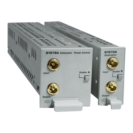
- Page 21 81576A Figure 5 Agilent 81576A High-power Attenuator with Power Control and Straight Connector Agilent 81577A 81577A Figure 6 Agilent 81577A High-power Attenuator with Power Control and Angled Connector Agilent 81570A, 71A, 76A, 77A & 78A Variable Optical Attenuators, Eigth Edition...
-
Page 22: Front Panel Controls And Indicators
81570A, 81571A, 81578A occupy one slot, while modules 81576A and 81577A occupy two slots. The Agilent 8166A/B Lightwave Multichannel System with its 17 slots can host up to 17 single slot modules (such as the 81570A attenuators) or up to 8 dual slot modules, (such as the 81577A attenuators). - Page 23 The difference between the power value read by the reference powermeter and the actual value of the attenuator is automatically stored as the offset. Agilent 81570A, 71A, 76A, 77A & 78A Variable Optical Attenuators, Eigth Edition...
-
Page 24: Optical Output
You cannot connect angled non-contact fiber end connectors with orange sleeves directly to the instrument. See “Accessories” on page 25 for further details on connector interfaces and accessories. Agilent 81570A, 71A, 76A, 77A & 78A Variable Optical Attenuators, Eigth Edition... - Page 25 Getting Started with Attenuator Modules Optical Output Agilent 81570A, 71A, 76A, 77A & 78A Variable Optical Attenuators, Eigth Edition...
-
Page 26: Accessories
Accessories Agilent 81570A, 71A, 76A, 77A & 78A Variable Optical Attenuators, Eigth Edition... - Page 27 This chapter describes the options and accessories available for the: • Agilent 81570A, 81571A VOA modules, • Agilent 81578A VOA modules for multimode applications; and the • Agilent 81576A and 81576A VOA modules with power control. Agilent 81570A, 71A, 76A, 77A & 78A Variable Optical Attenuators, Eigth Edition...
-
Page 28: Modules And Options
Connnector Interface for Connector Interface for 81000 SI DIN 47256 81000 SI DIN 4108.6 angled straight 81000 VI ST connectors connectors Figure 8 Mainframes, Variable Optical Attenuator Modules, and Options Agilent 81570A, 71A, 76A, 77A & 78A Variable Optical Attenuators, Eigth Edition... -
Page 29: Modules
Information” on page 77 on appropriate procedures for connector cleaning and inspection. However, Agilent Technologies Deutschland GmbH assumes no responsibility in case of an operation that is not compliace with the safety instructions as stated above. Agilent 81570A, 71A, 76A, 77A & 78A Variable Optical Attenuators, Eigth Edition... - Page 30 Variable Optical Attenuator Modules 1 Attach your connector interface to the interface adapter. See Figure 8 for a list of the available connector interfaces. 2 Connect your cable. Agilent 81570A, 71A, 76A, 77A & 78A Variable Optical Attenuators, Eigth Edition...
- Page 31 Accessories Connector Interfaces and Other Accessories Agilent 81570A, 71A, 76A, 77A & 78A Variable Optical Attenuators, Eigth Edition...
-
Page 32: Specifications
Specifications Agilent 81570A, 71A, 76A, 77A & 78A Variable Optical Attenuators, Eigth Edition... - Page 33 Information” on page 77 on appropriate procedures for connector cleaning and inspection. However, Agilent Technologies Deutschland GmbH assumes no responsibility in case of an operation that is not compliace with the safety instructions as stated above. Agilent 81570A, 71A, 76A, 77A & 78A Variable Optical Attenuators, Eigth Edition...
-
Page 34: Definition Of Terms
This section defines terms that are used both in this chapter and “Performance Tests” on page 47. Measurement principles are indicated. Alternative measurement principles of equal value are also acceptable. Agilent 81570A, 71A, 76A, 77A & 78A Variable Optical Attenuators, Eigth Edition... -
Page 35: Attenuation
Measurement: With an Erbium-Doped Fiber Amplifier to apply the necessary input power, tunable laser source, and optical power meter to probe the wavelength dependence of the attenuation drift. Agilent 81570A, 71A, 76A, 77A & 78A Variable Optical Attenuators, Eigth Edition... -
Page 36: Attenuation Range
This generally includes constant values of temperature, humidity, wavelength, input power level, polarization state and mode distribution (for multimode attenuators), if the quantity is not explicitly subject to variation. Agilent 81570A, 71A, 76A, 77A & 78A Variable Optical Attenuators, Eigth Edition... -
Page 37: Insertion Loss
The maximum input power level that can be applied to the attenuator without permanent change to its characteristics. NOTE For input powers > 20 dBm, clean connectors in good condition are vital to avoid thermally induced fiber damage. Agilent 81570A, 71A, 76A, 77A & 78A Variable Optical Attenuators, Eigth Edition... -
Page 38: Operating Temperature
Symbol RU. Conditions: Reference power level 1mW, wavelength and polarization state constant; power limitations as in the Specifications; zeroing prior to measurement. Agilent 81570A, 71A, 76A, 77A & 78A Variable Optical Attenuators, Eigth Edition... -
Page 39: Repeatability (Of Attenuation Or Total Loss)
Ratio between incident power and reflected power, expressed in dB. Applicable to both attenuator ports, with the respective second port terminated (zero reflectance). Conditions: Jumper cables with high quality connectors in perfect optical condition on both attenuator ports. Agilent 81570A, 71A, 76A, 77A & 78A Variable Optical Attenuators, Eigth Edition... -
Page 40: Settling Time
Spectral ripple does not include attenuation flatness or insertion loss flatness. Conditions: Constant operating conditions. Linewidth as specified. NOTE Spectral ripple results from interference between the passing wave and spurious internal reflections. Agilent 81570A, 71A, 76A, 77A & 78A Variable Optical Attenuators, Eigth Edition... -
Page 41: Total Loss
Specifies the settable attenuation change rate of the attenuator. Wavelength Range The range of wavelengths that can be set at the attenuator and for which the specifications apply (if not differently stated). Agilent 81570A, 71A, 76A, 77A & 78A Variable Optical Attenuators, Eigth Edition... -
Page 42: Specifications
45, which describes the Agilent 81576A and Agilent 81577A. • “Variable optical attenuator modules for multimode applications” on page 46, which describes the Agilent 81578A. Agilent 81570A, 71A, 76A, 77A & 78A Variable Optical Attenuators, Eigth Edition... - Page 43 Specifications Specifications - this page deliberately blank - Agilent 81570A, 71A, 76A, 77A & 78A Variable Optical Attenuators, Eigth Edition...
- Page 44 75 mm x 32 mm x 335 mm (2.8" x 1.3" x 13.2") Weight 0.9 kg Recommended recalibration period 2 years Operating temperature 10 °C - 45 °C Humidity Non-condensing Warm-up time 30 min. Agilent 81570A, 71A, 76A, 77A & 78A Variable Optical Attenuators, Eigth Edition...
- Page 45 0.01 dB ( a [db] - 20) for 1520 nm < < 1620 nm poorly cleanedconnectors. λ add typ. 0.02 dB ( a [db] - 20) for 1420 nm < < 1640 nm Agilent 81570A, 71A, 76A, 77A & 78A Variable Optical Attenuators, Eigth Edition...
- Page 46 Agilent Technologies Deutschland GmbH assumes no responsibility for damages caused by scratched or poorly cleaned connectors. Input power ≤ + 27 dBm, for input power > +27 dBm add ± 0.02 dB Agilent 81570A, 71A, 76A, 77A & 78A Variable Optical Attenuators, Eigth Edition...
- Page 47 The return loss is mainly limited by the return loss of the front panel connectors Agilent Technologies Deutschland GmbH assumes no responsibility for damages caused by scratched or poorly cleaned connectors. Agilent 81570A, 71A, 76A, 77A & 78A Variable Optical Attenuators, Eigth Edition...
-
Page 48: Performance Tests
Performance Tests Agilent 81570A, 71A, 76A, 77A & 78A Variable Optical Attenuators, Eigth Edition... -
Page 49: Required Test Equipment
Single Mode Fiber Diamond 253-183- FC/PC(a) to HMS-10(s) 003L002 Connector interface HMS-10 Agilent 81000AI Connector interface FC/PC Agilent 81000FI x x N-key Connector interface FC/APC Agilent 81000NI R-key Agilent 81570A, 71A, 76A, 77A & 78A Variable Optical Attenuators, Eigth Edition... - Page 50 NOTE: 2. Service tool, only available for Agilent service centers. Not available for trade sales. Legend: necessary not applicable optional (a) angled physical contact (s) straight physical contact Agilent 81570A, 71A, 76A, 77A & 78A Variable Optical Attenuators, Eigth Edition...
-
Page 51: Performance Test Procedure
Repeatability Test. Perform each step in the order given, using the corresponding test equipment. Operate the Agilent 81576A and 81577A Attenuator modules as attenuators and switch the power control loop off if not otherwise mentioned. Agilent 81570A, 71A, 76A, 77A & 78A Variable Optical Attenuators, Eigth Edition... -
Page 52: Insertion Loss Test
1. Turn the instruments on and allow the devices to warm up (20...30 min). 2. Make sure that all your connectors are clean and undamaged. 3. Connect the equipment as shown in Figure Agilent 81570A, 71A, 76A, 77A & 78A Variable Optical Attenuators, Eigth Edition... - Page 53 Record the power meter reading (in dB) as Insertion Loss in the Test Record. Connect the equipment as shown in Figure 10 on page 53. Setup for SM attenuators Agilent 81570A, 71A, 76A, 77A & 78A Variable Optical Attenuators, Eigth Edition...
-
Page 54: Accuracy Test
7 dB 8 dB 9 dB 10 dB 11 dB 12 dB 13 dB 14 dB 15 dB 25 dB 35 dB 45 dB 55 dB 60 dB Agilent 81570A, 71A, 76A, 77A & 78A Variable Optical Attenuators, Eigth Edition... -
Page 55: Repeatability Test
] back to the previous value and note the deviation of ] in the Test Record. Repeat step 6 to step 8 for [P ] = -25 dBm and [P ] = -50 dBm. Agilent 81570A, 71A, 76A, 77A & 78A Variable Optical Attenuators, Eigth Edition... -
Page 56: Wavelength Flatness Test (Not Applicable To 81578A)
Turn the instruments on and allow the devices to warm up (20...30 min). Make sure that all your connectors are clean and undamaged. Agilent 81570A, 71A, 76A, 77A & 78A Variable Optical Attenuators, Eigth Edition... - Page 57 5 mm (such as a screwdriver shaft, or a pencil). Do the same for the monitor output if applicable. Agilent 81570A, 71A, 76A, 77A & 78A Variable Optical Attenuators, Eigth Edition...
-
Page 58: Polarization Dependent Loss (Pdl) Test - Scanning Method (Not Applicable To 81578A)
Make sure that all your connectors are clean and undamaged. Connect the equipment as shown in Figure 13 Figure 13 PDL Test Setup - Scanning Method for SM attenuators Agilent 81570A, 71A, 76A, 77A & 78A Variable Optical Attenuators, Eigth Edition... -
Page 59: Polarization Dependent Loss (Pdl) Test - Mueller Method (Not Applicable To 81578A)
Turn the instruments on, and allow the devices to warm up (20...30 min). Make sure that all your connectors are clean and undamaged. Connect the equipment as shown in Figure 14 Agilent 81570A, 71A, 76A, 77A & 78A Variable Optical Attenuators, Eigth Edition... - Page 60 Get the values (possible by approximation) for the wavelength dependent offset positions for each type of polarization from Table 5, “Retarder Settings,” on page 62. Add these values to those for Linear Horizontal polarized light. Agilent 81570A, 71A, 76A, 77A & 78A Variable Optical Attenuators, Eigth Edition...
- Page 61 Right Hand Circular polarized light. Note the power reading as Reference Power P in the Test Record. Connect the equipment as shown in Figure 15 Agilent 81570A, 71A, 76A, 77A & 78A Variable Optical Attenuators, Eigth Edition...
- Page 62 Note the power reading as DUT Power P in the Test Record. Calculate the Mueller coefficients, the maximum and minimum transmission and finally the Polarization Dependent Loss (PDL) as described in the Test Record. Agilent 81570A, 71A, 76A, 77A & 78A Variable Optical Attenuators, Eigth Edition...
- Page 63 -15.1 1540 ° ° ° ° ° ° -1.4 44.3 -1.0 22.0 46.2 -13.8 1520 ° ° ° ° ° ° -2.7 43.6 -2.0 21.4 47.4 -12.4 1500 Agilent 81570A, 71A, 76A, 77A & 78A Variable Optical Attenuators, Eigth Edition...
- Page 64 Repeat step 14 and step 15 until the reference attenuator shows an attenuation of 0 dB. Perform step 14 and step 15 upward until the reference attenuator shows 55 dB. Agilent 81570A, 71A, 76A, 77A & 78A Variable Optical Attenuators, Eigth Edition...
- Page 65 Performance Tests Performance Test Procedure Agilent 81570A, 71A, 76A, 77A & 78A Variable Optical Attenuators, Eigth Edition...
- Page 66 Test Facility: Report No.: Date: Customer: Tested By: Model: Agilent High Power Optical Attenuator Product Number: ° Serial No. Ambient temperature Firmware Rev. Relative humidity Line frequency Special Notes: Agilent 81570A, 71A, 76A, 77A & 78A Variable Optical Attenuators, Eigth Edition...
- Page 67 Agilent High Power Optical Attenuator Report No. Date: Test Equipment Description Model No. Trace No. Cal. due date Mainframe Power Meter Laser Source Return Loss Module Connector Interface Single Mode Fiber Agilent 81570A, 71A, 76A, 77A & 78A Variable Optical Attenuators, Eigth Edition...
- Page 68 Upper test limit 1.5 dB 2.0 dB Attenuation Accuracy Test Setting/dB Reading/dB Deviation/dB Most positiveDeviation Upper test limit +0.1 dB Most negative Deviation Lower test limit -0.1 dB Agilent 81570A, 71A, 76A, 77A & 78A Variable Optical Attenuators, Eigth Edition...
- Page 69 0.14 dBpp Return Loss Test Product 81570A + 81576A 81571A/77A Attenuation Setting Shutter State Open Closed Measurement Input Port Measurement Output Port Lower test limit 42 dB 54 dB Agilent 81570A, 71A, 76A, 77A & 78A Variable Optical Attenuators, Eigth Edition...
- Page 70 ) - m DUT4 REF4 Minimum ans maximum Transmission – Product 81570A/71A 81576A + 81577A Polarization dependent loss PDL = 10lg(Tmax/Tmin) dBpp Upper test limit 0.8 dBpp 0.10 dBpp Agilent 81570A, 71A, 76A, 77A & 78A Variable Optical Attenuators, Eigth Edition...
- Page 71 Date Relative Power Meter Uncertainty Test 8157xA [P ]/ dBm Reference Attenuation/dB Reference Reading 1 /dB Reference Reading 2 /dB Maximum peak-to-peak deviation Upper test limit 0.06 dBpp Agilent 81570A, 71A, 76A, 77A & 78A Variable Optical Attenuators, Eigth Edition...
- Page 72 Wavelength 850 nm 1310 nm Setting/dB Reading/dB Deviation/dB Reading/dB Deviation/dB Most Positive Deviation Upper test limit +0.2dB +0.2 dB Most Negative Deviation Lower test limit -0.2dB -0.2 dB Agilent 81570A, 71A, 76A, 77A & 78A Variable Optical Attenuators, Eigth Edition...
- Page 73 Test Facility: Report No.: Date: Customer: Tested By: Model: Agilent High Power Optical Attenuator Product Number: ° Serial No. Ambient temperature Firmware Rev. Relative humidity Line frequency Special Notes: Agilent 81570A, 71A, 76A, 77A & 78A Variable Optical Attenuators, Eigth Edition...
- Page 74 Agilent High Power Optical Attenuator Report No. Date: Test Equipment Description Model No. Trace No. Cal. due date Mainframe Power Meter Laser Source Return Loss Module Connector Interface Single Mode Fiber Agilent 81570A, 71A, 76A, 77A & 78A Variable Optical Attenuators, Eigth Edition...
- Page 75 Date Attenuation Repeatability Test Wavelength 850 nm 1310 nm Setting / dB Deviation / dB Deviation / dB Maximum peak-to-peak Deviation Upper test limit 0.03 dBpp 0.03 dBpp Agilent 81570A, 71A, 76A, 77A & 78A Variable Optical Attenuators, Eigth Edition...
-
Page 76: Cleaning Information
Cleaning Information Agilent 81570A, 71A, 76A, 77A & 78A Variable Optical Attenuators, Eigth Edition... - Page 77 If you are unsure of the correct cleaning procedure for your optical device, we recommend that you first try cleaning a dummy or test device. Agilent Technologies assume no liability for the customer’s failure to comply with these requirements. Agilent 81570A, 71A, 76A, 77A & 78A Variable Optical Attenuators, Eigth Edition...
-
Page 78: Safety Precautions
Do not attempt to clean internally. • Do not install parts or perform any unauthorized modification to optical devices. • Refer servicing only to qualified and authorized personnel. Agilent 81570A, 71A, 76A, 77A & 78A Variable Optical Attenuators, Eigth Edition... -
Page 79: Why Is It Important To Clean Optical Devices
Additional Cleaning Equipment. Standard Cleaning Equipment Before you can start your cleaning procedure you need the following standard equipment: • Dust and shutter caps Agilent 81570A, 71A, 76A, 77A & 78A Variable Optical Attenuators, Eigth Edition... -
Page 80: Dust And Shutter Caps
If you need further dust caps, please contact your nearest Agilent Technologies sales office. Isopropyl alcohol This solvent is usually available from any local pharmaceutical supplier or chemist's shop. -
Page 81: Soft Tissues
The tip and center of the pipe cleaner are made of metal. Avoid accidentally pressing these metal parts against the inside of the device, as this can cause scratches. Compressed air Compressed air can be purchased from any laboratory supplier. Agilent 81570A, 71A, 76A, 77A & 78A Variable Optical Attenuators, Eigth Edition... -
Page 82: Additional Cleaning Equipment
An ultrasonic bath will gently remove fat and other stubborn dirt from your optical devices. This helps increase the life span of the optical devices. Only use isopropyl alcohol in your ultrasonic bath, as other solvents may cause damage. Agilent 81570A, 71A, 76A, 77A & 78A Variable Optical Attenuators, Eigth Edition... -
Page 83: Warm Water And Liquid Soap
Take care never to look into the end of a fiber or any other optical component, when they are in use. This is because the laser can seriously damage your eyes. Agilent 81570A, 71A, 76A, 77A & 78A Variable Optical Attenuators, Eigth Edition... -
Page 84: Preserving Connectors
Opening the instrument can cause damage to sensitive components, and in addition your warranty will be invalidated. Agilent 81570A, 71A, 76A, 77A & 78A Variable Optical Attenuators, Eigth Edition... -
Page 85: General Cleaning Procedure
The fiber end faces must be visually inspected using a microscope with a magnification of at leasst 400x. For recommended fiber inspection microscopes, please refer to personnel in Agilent’s Service Team. Agilent 81570A, 71A, 76A, 77A & 78A Variable Optical Attenuators, Eigth Edition... -
Page 86: How To Clean Optical Head Adapters
Some adapters have an anti-reflection coating on the back to reduce back reflection. This coating is extremely sensitive to solvents and mechanical abrasion. Extra care is needed when cleaning these adapters. Agilent 81570A, 71A, 76A, 77A & 78A Variable Optical Attenuators, Eigth Edition... -
Page 87: How To Clean Connector Interfaces
3 Using a new, dry pipe cleaner, and a new, dry cotton swab remove the alcohol, any dissolved sediment and dust. 4 Blow away any remaining lint with compressed air. Agilent 81570A, 71A, 76A, 77A & 78A Variable Optical Attenuators, Eigth Edition... -
Page 88: How To Clean Bare Fiber Adapters
Particles on the optical head’s front window can significantly impair measurement results. N O T E Do not dry the lens by rubbing with with cloth or other material, which may scratch the lens surface. Agilent 81570A, 71A, 76A, 77A & 78A Variable Optical Attenuators, Eigth Edition... -
Page 89: How To Clean Instruments With A Fixed Connector Interface
How to clean instruments with a physical contact interface Remove any connector interfaces from the optical output of the instrument before you begin the cleaning procedure. Agilent 81570A, 71A, 76A, 77A & 78A Variable Optical Attenuators, Eigth Edition... - Page 90 The fiber end faces must be visually inspected using a microscope with a magnification of at least 400x. For recommended fiber inspection microscopes, please refer to Agilent 's service team personnel. Agilent 81570A, 71A, 76A, 77A & 78A Variable Optical Attenuators, Eigth Edition...
-
Page 91: How To Clean Instruments With A Recessed Lens Interface
Preferred Procedure Use the following procedure on most occasions. 1 Blow away any dust or dirt with compressed air. Agilent 81570A, 71A, 76A, 77A & 78A Variable Optical Attenuators, Eigth Edition... -
Page 92: How To Clean Metal Filters Or Attenuator Gratings
2 Remove the fluid using compressed air at some distance and with low pressure. If there are any streaks or drying stains on the surface, repeat the whole cleaning procedure. Agilent 81570A, 71A, 76A, 77A & 78A Variable Optical Attenuators, Eigth Edition... -
Page 93: Additional Cleaning Information
Use the following procedure on most occasions. 1 Blow away any dust or dirt with compressed air. Procedure for Stubborn Dirt Use this procedure when there is greasy dirt on the lens: Agilent 81570A, 71A, 76A, 77A & 78A Variable Optical Attenuators, Eigth Edition... - Page 94 2 Take a new, dry soft tissue and remove the alcohol, dissolved sediment and dust, by rubbing gently over the surface using a small circular movement. 3 Blow away remaining lint with compressed air. Agilent 81570A, 71A, 76A, 77A & 78A Variable Optical Attenuators, Eigth Edition...
-
Page 95: Other Cleaning Hints
Never open the instruments as they can be damaged. Opening the instruments puts you in danger of receiving an electrical shock from your device, and renders your warranty void. Agilent 81570A, 71A, 76A, 77A & 78A Variable Optical Attenuators, Eigth Edition... - Page 96 Shutter Isolation 29 Total Loss 30 Transition speed 30 Wavelength range 30 Firmware Prerequisites 4 Revision Checking 6 Front Panel Agilent 81570A 8 Agilent 81571A 8 Agilent 81576A 10 Agilent 81570A, 71A, 76A, 77A & 78A Variable Optical Attenuators, Eigth Edition...
- Page 97 Variable optical attenuator modules for single mode applications 32 Variable optical attenuator modules with power control for single mode applications 33 Storage & Shipment 4 Use Models 11 User’s Guides 18 Wavelength flatness test 43 Agilent 81570A, 71A, 76A, 77A & 78A Variable Optical Attenuators, Eigth Edition...
- Page 99 Agilent Technologies GmbH 2005 Printed in Germany September 2005 Eight edition, September 2005 81570-90A01 Agilent Technologies...