Table of Contents
Advertisement
Quick Links
Advertisement
Table of Contents

Related Manuals for Agilent Technologies 83487A


Summary of Contents for Agilent Technologies 83487A
- Page 1 Agilent 83487A Optical/Electrical Plug-In Module User’s Guide...
- Page 2 Agency. country. The information contained in WARNING this document is subject to This text denotes the Agilent Technologies war- ISM1-A change without notice. Com- The warning sign denotes a instrument is an rants that its software and panies, names, and data used hazard.
-
Page 3: The Agilent 83487A-At A Glance
• One auxiliary power connector. NOTE If you wish to use the Agilent 83487A optical plug-in module in an Agilent 54750A digi- tizing oscilloscope, a firmware upgrade must first be installed. Order the Agilent 83480K communications firmware kit and follow the installation instructions. - Page 4 INPUT connector is no exception. When you use improper cleaning and handling tech- niques, you risk expensive instrument repairs, damaged cables, and compromised mea- surements. Before you connect any fiber-optic cable to the Agilent 83487A optical/electrical plug-in module, refer to “Cleaning Connections for Accurate Measurements” on page 5-14.
- Page 5 (in which all means for protection are intact) only. W A R N I N G To prevent electrical shock, disconnect the Agilent 83487A optical/ electrical plug-in module from mains before cleaning. Use a dry cloth or one slightly dampened with water to clean the external case parts.
- Page 6 General Safety Considerations W A R N I N G For continued protection against fire hazard, replace line fuse only with same type and ratings, (type T 0.315A/250V for 100/120V operation and 0.16A/250V for 220/240V operation). The use of other fuses or materials is prohibited.
- Page 7 General Safety Considerations C A U T I O N Electrostatic discharge (ESD) on or near input connectors can damage circuits inside the instrument. Repair of damage due to misuse is not covered under warranty. Before connecting any cable to the electrical input, momentarily short the center and outer conductors of the cable together.
- Page 8 General Safety Considerations viii...
-
Page 9: Table Of Contents
Contents The Agilent 83487A—At a Glance iii 1 Getting Started The Agilent 83487A Optical/Electrical Plug-In Module 1-3 Options and Accessories 1-7 Menu and Key Conventions 1-9 Step 1. Inspect the Shipment 1-10 Step 2. Install the Plug-in Module 1-11 Returning the Instrument for Service 1-12... -
Page 11: Getting Started
The Agilent 83487A Optical/Electrical Plug-In Module 1-3 Options and Accessories 1-7 Menu and Key Conventions 1-9 Step 1. Inspect the Shipment 1-10 Step 2. Install the Plug-in Module 1-11 Returning the Instrument for Service 1-12 Getting Started... - Page 12 This chapter gives a description of the plug-in module, lists options and acces- sories, explains menu and key conventions used, shows how to install your Agilent 83487A, and gives information for returning the plug-in module for service. Refer to Chapter 2, “Channel Setup Menu” for information on operating the plug-in module.
-
Page 13: The Agilent 83487A Optical/Electrical Plug-In Module
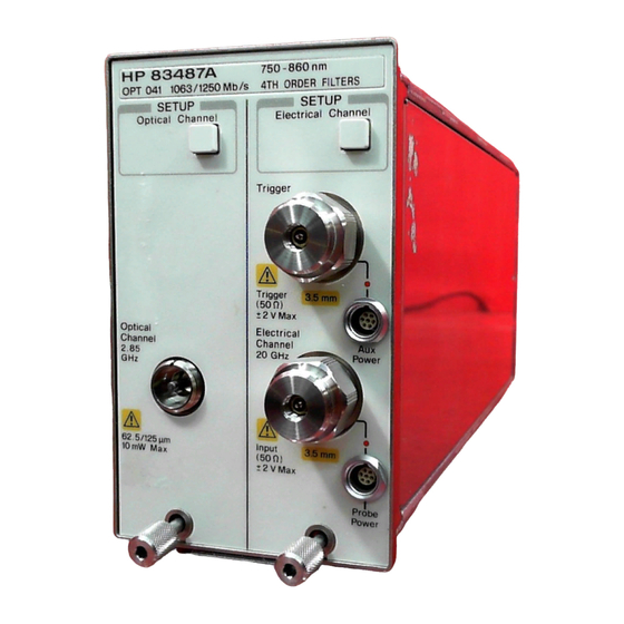
750 nm and 860 nm using a source and power meter. The Agilent 83487A also is a calibrated reference receiver that is measured to conform to specifications for Fibre Channel (FC) 1063 and Gigabit Ethernet for transmitter compliance testing. By pressing a front-panel key or issuing an GPIB command, a filter is inserted or removed from the measurement channel by a very repeatable Agilent Technologies microwave switch. - Page 14 Getting Started The Agilent 83487A Optical/Electrical Plug-In Module The Agilent 83487A provides: • 2.85 GHz, integrated, calibrated optical channel with sensitivity to below –17 dBm • 12.4 GHz and 20 GHz electrical channel • Trigger channel input to the mainframe •...
- Page 15 Getting Started The Agilent 83487A Optical/Electrical Plug-In Module Front panel of the plug-in module The plug-in module takes up two of the four mainframe slots. The optical channel provides calibrated measurement of optical waveforms in power units. The electrical channel provides calibrated measurement of electrical signals in volts.
- Page 16 Getting Started The Agilent 83487A Optical/Electrical Plug-In Module Trigger The external trigger level range for this plug-in module is ±1 V. The trigger source selection depends on the plug-in module location. For example, if the plug-in module is installed in slots 1 and 2, then the trigger source is listed as trigger 2.
-
Page 17: Options And Accessories
Getting Started Options and Accessories Options and Accessories Options Option 0B1 Additional set of user documentation Option 0B0 Deletes the user documentation Option UK6 Measured performance data Option 001 Latest version of operating firmware for the Agilent 83480A Option 002 Latest version of operating firmware for the Agilent 54750A Option 011 Diamond HMS-10 connector interface... - Page 18 Getting Started Options and Accessories Connection devices Agilent 1250-1158 SMA (f-f) adapter Agilent 1250-1749 APC 3.5 (f-f) adapter Agilent 81000FI FC/PC/SPC/APC connector interface Agilent 81000KI SC connector interface Agilent 81000SI DIN 47256/4108.6 connector interface Agilent 81000VI ST connector interface Agilent 81000WI Biconic...
-
Page 19: Menu And Key Conventions
Getting Started Menu and Key Conventions Menu and Key Conventions The keys labeled Trigger, Disk, and Run are all examples of front-panel keys. Some front-panel keys bring up menus on the right side of the display screen. These menus are called softkey menus. Softkey menus contain functions not available directly by pressing the front- panel keys. -
Page 20: Step 1. Inspect The Shipment
• SMA 50Ω termination, Agilent part number 1810-0118, 2 each If your shipment is damaged or incomplete, save the packing materials and notify both the shipping carrier and the nearest Agilent Technologies service office. Agilent Technologies will arrange for repair or replacement of damaged or incomplete shipments without waiting for a settlement from the transporta- tion company. -
Page 21: Step 2. Install The Plug-In Module
You do not need to turn off the mainframe to install or remove the plug-in modules. Note If you wish to use the Agilent 83487A in an Agilent 54750A digitizing oscilloscope, a firmware upgrade must first be installed. Order the Agilent 83480K communications firmware kit and follow the installation instructions. -
Page 22: Returning The Instrument For Service
Technologies Service Offices” on page 5-24 for a list of service offices. Agilent Technologies Instrument Support Center ... (800) 403-0801 If the instrument is still under warranty or is covered by an Agilent Technolo- gies maintenance contract, it will be repaired under the terms of the warranty or contract (the warranty is at the front of this manual). - Page 23 They may also cause instrument damage by generating static electricity. 3 Pack the instrument in the original shipping containers. Original materials are available through any Agilent Technologies office. Or, use the following guidelines: • Wrap the instrument in antistatic plastic to reduce the possibility of damage caused by electrostatic discharge.
- Page 24 Getting Started Returning the Instrument for Service Sealed Air Corporation (Commerce, California 90001). Air Cap looks like a plastic sheet filled with air bubbles. Use the pink (antistatic) Air Cap™ to reduce static electricity. Wrapping the instrument several times in this ma- terial will protect the instrument and prevent it from moving in the carton.
-
Page 25: Channel Setup Menu
Channel Setup Menu 2-2 Displaying the Channel Setup Menus 2-5 Channel Setup Menu... - Page 26 Channel Setup Menu Channel Setup Menu Channel Setup Menu This chapter describes the Channel Setup menu. A key tree and description of the available functions is included. C A U T I O N The input circuits can be damaged by electrostatic discharge (ESD). Therefore, avoid applying static discharges to the front-panel input connectors.
- Page 27 Channel Setup Menu Channel Setup Menu Figure 2-1. Optical Channel Setup menu.
- Page 28 Channel Setup Menu Channel Setup Menu Figure 2-2. Electrical Channel Setup menu.
-
Page 29: Displaying The Channel Setup Menus
Channel Setup Menu Displaying the Channel Setup Menus Displaying the Channel Setup Menus To display the optical Channel Setup menu, press the Optical Channel key located above the optical input connector. To display the electrical Channel Setup menu, press the Electrical Channel key located above the electrical input connector. - Page 30 Channel Setup Menu Display Display The Display softkey turns the channel display off and on. When the channel dis- play is on, a waveform is displayed for that channel, unless the offset is adjusted so the waveform is clipped off the display. The channel number, vertical scaling, and offset are displayed at the bottom left of the waveform area.
- Page 31 Channel Setup Menu Offset Offset The Offset softkey moves the waveform vertically. It is similar to the position control on analog oscilloscopes. The advantage of digital offset is that it is cali- brated. The offset voltage for electrical channels is the voltage at the center of the graticule area, and the range of offset is ±12 times the full resolution chan- nel scale.
- Page 32 Channel Setup Menu Channel autoscale Channel, Bandwidth/Wavelength.., Filter On Off Key Path Wavelength This function is available on the optical channel only. The Wavelength function selects the desired wavelength for calibrated mea- surements. The factory calibrated wavelength is 850 nm. A user-calibrated wavelength is also available and can be calibrated in the range from 750 nm to 860 nm.
- Page 33 Channel Setup Menu External scale..External scale..The External scale softkey allows you to set up the analyzer to use external opti- cal-to-electrical converters or attenuators. Scaling is automatically adjusted to account for the external device. Key Path Channel, External scale..Atten units The Atten units function lets you select how you want the probe attenuation factor represented.
- Page 34 Channel Setup Menu External scale..Units The Units function lets you select the unit of measure appended to the channel scale, offset, trigger level, and vertical measurement values. For the optical channel these units are Volts or Watts. For the electrical channel the units are Volts, Amperes, Watts, or unknown.
- Page 35 Channel Setup Menu Calibrate Calibrate The Calibrate softkey allows you to null any skew between probes or cables, remove the effects of offsets in the internal O/E converter, recalibrate the responsivity of the O/E converter, and check the present calibration status of the analyzer.
- Page 36 Channel Setup Menu Calibrate Cal status The Cal status function displays a screen similar to Figure 2-3. Channel, Calibrate, Cal Status Key Path Figure 2-3. A typical Cal Status display. This is the current date and time. You can compare this to the last plug-in Current Date module calibration time to see how long it has been since calibration was per- formed.
- Page 37 The analyzer also automatically compensates for any offset the probe may introduce. The CAL signal is inter- nally routed to the probe tip for Agilent Technologies probes. Channel, Calibrate, Calibrate probe Key Path...
-
Page 39: Calibration Overview
Factory Calibrations 3-4 User Calibrations—Optical and Electrical 3-7 Complete Calibration Summary 3-19 Calibration Overview... - Page 40 Calibration Overview Calibration Overview Calibration Overview This chapter describes the calibration of the mainframe and the plug-in mod- ules. It is intended to give you, or the calibration laboratory personnel, an understanding of the various calibration procedures available, and how they were intended to be used.
- Page 41 Calibration interval Agilent Technologies recommends that the factory calibration be performed on a periodic basis. Agilent Technologies designs instruments to meet specifi- cations over the recommended calibration interval provided that the instru- ment is operated within the specified operating environment. To maintain specifications, periodic recalibrations are necessary.
-
Page 42: Factory Calibrations
Calibration Overview Factory Calibrations Factory Calibrations The following calibrations are performed at the factory: Mainframe Calibration O/E Factory Wavelength Calibration Table 3-1. Factory Calibration Summary Measurements Recommended Calibration What is calibrated Softkey Path Affected Interval Mainframe Accuracy and Channels affected: Annually at Agilent Utility Calibration... - Page 43 Calibration Overview Factory Calibrations optional Agilent 83480A, 54750A Service Guide for more details about the mainframe calibration, and the position of the rear-panel memory protect switches. C A U T I O N To prevent access to the mainframe calibration switch, place a sticker over the access hole to this switch.
- Page 44 Calibration Overview Factory Calibrations If the Current Frame ∆Temp listing is greater than ±5°C, then the main- frame should either be calibrated at the current operating temperature or be placed in an ambient air temperature that is within 5°C of the temperature of the current calibration.
-
Page 45: User Calibrations-Optical And Electrical
Calibration Overview User Calibrations—Optical and Electrical User Calibrations—Optical and Electrical The following calibrations can be performed by the user: O/E User Wavelength Calibration Plug-in Module Vertical Calibration Offset Zero Calibration Dark Calibration Probe Calibration Channel Skew External Scale Electrical channels have calibration procedures for: •... - Page 46 Calibration Overview User Calibrations—Optical and Electrical Table 3-2. Optical and Electrical Channel User Calibration Summary Measurements Recommended Calibration What is calibrated Key Path Affected Interval O/E User Wavelength The photodetector Channels affected: Annual re-calibration Optical Channel Setup Calibration responsivity optical. All optical of user defined non- Calibrate channel...
- Page 47 Calibration Overview User Calibrations—Optical and Electrical Table 3-3. Miscellaneous User Calibration Summary Measurements Recommended Calibration What is calibrated Key Path Affected Interval Probe calibration Probe Attenuation Channels affected: Whenever a probe is Electrical Channel Setup electrical. Any connected Calibrate electrical Calibrate probe measurement taken with the probe...
- Page 48 Calibration Overview User Calibrations—Optical and Electrical NOTE The optical channel calibration accuracy is heavily dependent on the accuracy to which you know the optical source power. For best results, measure the optical source power with an optical power meter such as the Agilent 8153A and use precision optical con- nectors.
- Page 49 Calibration Overview User Calibrations—Optical and Electrical Plug-in Module Vertical Calibration The plug-in module vertical calibration is for both optical and electrical mea- surements. It allows the instrument to establish the calibration factors for a specific plug-in when the plug-in is installed in the mainframe. The plug-in cal- ibration factors are valid only for the specific mainframe slot in which it was calibrated.
- Page 50 Calibration Overview User Calibrations—Optical and Electrical No additional equipment is required to perform a plug-in vertical calibration. Reference signals are both generated and routed internally, for the optical and electrical channels. If you are prompted to connect the calibrator output to the electrical channel during an optical vertical calibration, then the factory O/E calibration has been lost.
- Page 51 Calibration Overview User Calibrations—Optical and Electrical Figure 3-3. Offset Zero Calibration Dark Calibration The dark calibration is for optical measurements, or electrical measurements if an external O/E is being used. This calibration measures the optical channel offset signal when there isn’t any light present and then uses this information in performing extinction ratio measurements.
- Page 52 Calibration Overview User Calibrations—Optical and Electrical To initiate a dark calibration 1 Press the Display key. Press the Color grade softkey, and set its setting to on. Color grade must be enabled to perform an extinction ratio measurement and a dark calibration. In addition, the dark level (amplitude when there is no signal present) must be on the screen to perform a dark calibration.
- Page 53 The analyzer calibrates to the tip of the probe by setting the probe attenuation to the actual attenuation ratio of the probe. The CAL signal is internally routed to the probe tip for Agilent Technologies active probes. 3-15...
- Page 54 You can use the probe calibration to calibrate any network, including probes or cable assemblies. The instrument calibrates the voltage at the tip of the probe or the cable input. To calibrate an Agilent Technologies identifiable probe 1 Press the plug-in module’s front-panel-channel SETUP key. 2 Press Calibrate and then Calibrate Probe.
- Page 55 Calibration Overview User Calibrations—Optical and Electrical Figure 3-5. Electrical Channel Calibrate Menu To calibrate other devices The information in this section applies to both optical and electrical measure- ments. Since the mainframe’s CAL signal is a voltage source, it cannot be used to calibrate to the probe tip when the units are set to Ampere, Watt, or Unknown.
- Page 56 Calibration Overview User Calibrations—Optical and Electrical External Scale Both optical and electrical channels have an External scale setting which allows the user to enter in an offset value to compensate for gains or losses not associated with the device under test. This feature is useful for adjusting out the effects of devices such as test fixtures and attenuators so that the reading on the display gives the measurement value associated with only the actual device under test.
-
Page 57: Complete Calibration Summary
Calibration Overview Complete Calibration Summary Complete Calibration Summary Table 3-4. Complete Calibration Summary (1 of 2) Measurements Recommended Calibration What is calibrated Key Path Affected Interval Mainframe Calibration Accuracy and Channels affected: Annually at Agilent Utility continuity of the optical & electrical. All service center or if Calibrate timescale... - Page 58 Calibration Overview Complete Calibration Summary Table 3-4. Complete Calibration Summary (2 of 2) Measurements Recommended Calibration What is calibrated Key Path Affected Interval Offset Zero Calibration Vertical offset is Channels affected: Perform a plug-in Optical Channel Setup calibrated for the optical.
- Page 59 Specifications 4-3 Characteristics 4-8 Declaration of Conformity 4-9 Specifications and Regulatory Information...
- Page 60 Specifications and Regulatory Information Specifications and Regulatory Information Specifications and Regulatory Information This chapter lists specifications and characteristics of the Agilent 83487A. Specifications apply over the temperature range +15°C to +35°C (unless oth- erwise noted) after the instrument’s temperature has been stabilized after 60 minutes of continuous operation.
- Page 61 Specifications and Regulatory Information Specifications Specifications Table 4-1. Agilent 83487A Electrical Channel Vertical Specifications Bandwidth (–3 dB) dc to 12.4 GHz or 20 GHz, user selectable dc Accuracy—single voltage marker ± 12.4 GHz 0.4% of full scale ± ± 2 mV 1.5% (reading –...
- Page 62 Specifications and Regulatory Information Specifications Table 4-1. Agilent 83487A Electrical Channel Vertical Specifications (Continued) ≤ 20 GHz 1 mV (0.5 mV typical) Scale Factor (full scale is eight divisions) Minimum 1 mV/div Maximum 100 mV/div ± dc Offset Range 500 mV Ω...
- Page 63 Specifications and Regulatory Information Specifications Table 4-2. Agilent 83487A Optical Channel Vertical Specifications Bandwidth (–3 dB) dc to 2.85 GHz (dc to 3.0 GHz characteristic) Maximum Specified Peak Input Power Continuous Wave 0.6 mW (–2.2 dBm) Modulated 0.4 mW (–4 dBm) ±...
-
Page 64: Specifications And Regulatory Information Specifications
Specifications and Regulatory Information Specifications Table 4-2. Agilent 83487A Optical Channel Vertical Specifications (Continued) µ µ Specified operating range (average power) –30 dBm to –2.2 dBm (1 W to 500 µ Maximum peak power input (typical) (4000 W (6 dBm) typical) °... - Page 65 Specifications and Regulatory Information Specifications Table 4-4. Power Requirements Supplied by mainframe. Table 4-5. Weight approximately 1.2 kg (2.6 lb.) Shipping approximately 2.1 kg (4.6 lb.)
-
Page 66: Characteristics
Specifications and Regulatory Information Characteristics Characteristics The following characteristics are typical for the Agilent 83487A. Refer to the Agilent 54701A Active Probe Service Guide for complete probe characteris- tics. Table 4-6. Trigger Input Characteristics for Electrical and Optical Channels Ω... -
Page 67: Declaration Of Conformity
Specifications and Regulatory Information Declaration of Conformity Declaration of Conformity... -
Page 69: Reference
In Case of Difficulty 5-2 Measuring High Power Waveforms 5-6 Error Messages 5-10 Electrostatic Discharge Information 5-12 Cleaning Connections for Accurate Measurements 5-14 Agilent Technologies Service Offices 5-24 Reference... -
Page 70: In Case Of Difficulty
A list of messages that may be displayed is also included in this chapter. Review the procedure being performed when the problem occurred. Before calling Agilent Technologies or returning the unit for service, a few minutes spent performing some simple checks may save waiting for your instrument to be repaired. - Page 71 Reference In Case of Difficulty If the mainframe does not operate Make the following checks: • Is the line fuse good? • Does the line socket have power? • Is the unit plugged in to the proper ac power source? •...
- Page 72 Reference In Case of Difficulty If the plug-in does not operate 1 Make the following checks: • Is the plug-in module firmly seated in the mainframe slot? • Are the knurled screws at the bottom of the plug-in module finger-tight? •...
- Page 73 3.5 inch diskette. To load new firmware, follow the instructions provided with this diskette. If you do not have the optional diskette, contact your local Agilent Technologies Service Office (refer to “Agilent Technologies Service Offices” on page 5-24).
-
Page 74: Measuring High Power Waveforms
(3 dB). A basic rule of thumb for signals with up to 100% overshoot is that the average power should not exceed 100 µW (–10 dBm). 1. While the Agilent 83487A module is specified to receive a continuous wave peak power of up µ to 600 W (–2.2 dBm), high frequency ringing in a modulated signal can cause compression... - Page 75 Average power can be measured directly using the internal power meter of the Agilent 83487A, by pressing: blue Shift key, More meas key on the numeric keypad and then the Avg Power softkey. Then select the data to be reported in dBm.
- Page 76 In order to find out if your device under test may be exceeding the input power requirements for the Agilent 83487A, first measure the average power with the internal power meter, and then measure the peak power on the eye diagram.
- Page 77 Agilent 83480/Agilent 83487A, or • when you know there is no high frequency ringing associated with the device under test and you want to use the high sensitivity of the Agilent 83487A. C A U T I O N...
-
Page 78: Error Messages
Reference Error Messages Error Messages The following error messages are for the plug-in module. Typically, the error messages indicate there is a problem with either the plug-in or the mainframe. This section explains what the messages mean and offers a few suggestions that might help resolve the error condition. - Page 79 2 Verify the plug-in module is firmly seated in the mainframe slot. 3 Verify the knurled screws at the bottom of the plug-in module are finger tight. 4 The standard Agilent 54750A mainframe does not accept the Agilent 83487A optical/electrical plug-in module. To use the module, a firmware upgrade must first be installed.
-
Page 80: Electrostatic Discharge Information
Reference Electrostatic Discharge Information Electrostatic Discharge Information Electrostatic discharge (ESD) can damage or destroy electronic components. All work on electronic assemblies should be performed at a static-safe work station. The following figure shows an example of a static-safe work station using two types of ESD protection: •... - Page 81 Reference Electrostatic Discharge Information Both types, when used together, provide a significant level of ESD protection. Of the two, only the table-mat and wrist-strap combination provides adequate ESD protection when used alone. To ensure user safety, the static-safe accessories must provide at least 1 MΩ of isolation from ground.
-
Page 82: Cleaning Connections For Accurate Measurements
Connectors also vary in the polish, curve, and concentricity of the core within the cladding. Mating one style of cable to another requires an adapter. Agilent Technologies offers adapters for most instruments to allow testing with many different cables. - Page 83 Reference Cleaning Connections for Accurate Measurements tions take repeatability uncertainty into account? • Will a connector degrade the return loss too much, or will a fusion splice be re- quired? For example, many DFB lasers cannot operate with reflections from connectors.
- Page 84 0.2 µm. This process, plus the keyed axis, allows very precise core-to-core alignments. This connector is found on most Agilent Technologies lightwave instruments. 5-16...
- Page 85 Reference Cleaning Connections for Accurate Measurements The soft core, while allowing precise centering, is also the chief liability of the connector. The soft material is easily damaged. Care must be taken to mini- mize excessive scratching and wear. While minor wear is not a problem if the glass face is not affected, scratches or grit can cause the glass fiber to move out of alignment.
- Page 86 Reference Cleaning Connections for Accurate Measurements Use the following guidelines to achieve the best possible performance when making measurements on a fiber-optic system: • Never use metal or sharp objects to clean a connector and never scrape the connector. • Avoid matching gel and oils. Figure 5-4.
- Page 87 Reference Cleaning Connections for Accurate Measurements Figure 5-6. Damage from improper cleaning. While these often work well on first insertion, they are great dirt magnets. The oil or gel grabs and holds grit that is then ground into the end of the fiber. Also, some early gels were designed for use with the FC, non-contacting con- nectors, using small glass spheres.
- Page 88 Reference Cleaning Connections for Accurate Measurements • Keep connectors covered when not in use. • Use fusion splices on the more permanent critical nodes. Choose the best con- nector possible. Replace connecting cables regularly. Frequently measure the return loss of the connector to check for degradation, and clean every connec- tor, every time.
- Page 89 Cleaning Connectors The procedures in this section provide the proper steps for cleaning fiber- optic cables and Agilent Technologies universal adapters. The initial cleaning, using the alcohol as a solvent, gently removes any grit and oil. If a caked-on layer of material is still present, (this can happen if the beryllium-copper sides of the ferrule retainer get scraped and deposited on the end of the fiber during insertion of the cable), a second cleaning should be performed.
- Page 90 Reference Cleaning Connections for Accurate Measurements Table 5-4. Dust Caps Provided with Lightwave Instruments Item Agilent Part Number Laser shutter cap 08145-64521 FC/PC dust cap 08154-44102 Biconic dust cap 08154-44105 DIN dust cap 5040-9364 HMS10/dust cap 5040-9361 ST dust cap 5040-9366 To clean a non-lensed connector C A U T I O N...
- Page 91 To clean an adapter The fiber-optic input and output connectors on many Agilent Technologies instruments employ a universal adapter such as those shown in the following picture. These adapters allow you to connect the instrument to different types of fiber-optic cables.
-
Page 92: Agilent Technologies Service Offices
Reference Agilent Technologies Service Offices Agilent Technologies Service Offices Before returning an instrument for service, call the Agilent Technologies Instrument Support Center at (800) 403-0801, visit the Test and Measurement Web Sites by Country page at http://www.tm.agilent.com/tmo/country/English/ index.html, or call one of the numbers listed below. - Page 93 Index Channel autoscale softkey, Channel key, 1-2, accessories and options, classification active probe, product, Agilent offices, 5-24 cleaning Atten units softkey, adapters, 5-23 attenuation cabinet, range, fiber-optic connections, 5-14, 5-22 Attenuation softkey, non-lensed connectors, 5-22 attenuator, scaling, 2-9, compressed dust remover, 5-21 automatic measurement, connection devices,...
- Page 94 Index connectors, covering, 1-13 optical-to-electrical converter scaling, Filter key, options and accessories, foam swabs, 5-21 front panel overview, fuse, 1-11 packaging for shipment, 1-13 values, plug-in message, 2-13 plug-in module features, high power signals, front panel, horizontal waveform, 2-11 serial number, 1-10 plug-in module vertical calibration, 3-11...
- Page 95 Index specifications, swabs, 5-21 technical assistance, temperature change, 2-13 trigger external, level, 2-10 source, troubleshooting, Units softkey, 2-6, 2-10 user calibrations, vertical measurement, 2-10 scale, 2-6–2-8 waveform, voltage measurement, probe, 2-13 voltage probe calibration, 3-15 wattage measurement, waveform display, horizontal, 2-11 waveforms high power,...