Table of Contents
Advertisement
Quick Links
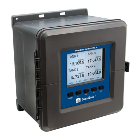
PD9000 ConsoliDator+ Multivariable Controller
Instruction Manual
NEMA 4X Panel or Field Mount Multi-Channel Controller
•
Convenient Display, Control, & Alarm of Multiple 4-20 mA & Pulse Inputs
•
Numeric & Bargraph Color Display (320 x 240 px) 5.7" (145 mm)
•
Sunlight Readable Display, White Backlight
•
•
Isolated 24 VDC Transmitter Supplies 200 mA / Analog Input; 1,600 mA Max
•
99 Channels, 32 Totalizers, 32 Timers, & 199 Modbus Slave Inputs
64 High & Low Alarms assigned to up to 25 Relays with AND/OR Logic
•
•
Modular Design for Input & Output Flexibility
Up to (28) 4-20 mA Isolated Inputs or Pulse Inputs
•
Up to (25) 10 Amp Form C Relays (With Eight Analog or Pulse Inputs)
•
Up to (25) Isolated 4-20 mA Outputs (With Eight Analog or Pulse Inputs)
•
Operating Temperature Range: -40 to 60°C (-40 to 140°F)
•
Pulse, Analog, & Modbus Input Flow Rate / Total / Grand Total Capability
•
•
50-Point Linearization, Square Root, and Exponent for Open Channel Flow
•
Round Horizontal Tank Volume Calculation; Just Enter Diameter & Length
•
Multi-Pump Alternation Control or Simple On / Off Control
Programmable Displays, Function Keys & Digital Inputs
•
Math Functions: Sum, Diff, Average, Multiply, Divide, % Efficiency, & More
•
Display Direct Modbus PV Inputs – Slave Mode
•
RS-485 Modbus RTU Standard & Ethernet Modbus TCP/IP Optional
•
•
Free ConsoliDator+ Configuration Software
•
3 Year Warranty
PRECISION DIGITAL CORPORATION
233 South Street • Hopkinton MA 01748 USA
Tel (800) 343-1001 • Fax (508) 655-8990
Multi-Channel Controller
www.predig.com
Advertisement
Table of Contents

Subscribe to Our Youtube Channel
Related Manuals for Precision Digital Corporation ConsoliDator+


Summary of Contents for Precision Digital Corporation ConsoliDator+
- Page 1 Display Direct Modbus PV Inputs – Slave Mode • RS-485 Modbus RTU Standard & Ethernet Modbus TCP/IP Optional • • Free ConsoliDator+ Configuration Software • 3 Year Warranty PRECISION DIGITAL CORPORATION 233 South Street • Hopkinton MA 01748 USA Tel (800) 343-1001 • Fax (508) 655-8990 www.predig.com...
- Page 2 Limited Warranty Precision Digital Corporation warrants this product against defects in material or workmanship for the specified period under “Specifications” from the date of shipment from the factory. Precision Digital’s liability under this limited warranty shall not exceed the purchase value, repair, or replacement of the defective unit.
-
Page 3: Table Of Contents
PD9000 ConsoliDator+ Multivariable Controller Instruction Manual Table of Contents Channel Parameters ..........27 INTRODUCTION ..........5 Data Entry Keypad ..........28 ORDERING INFORMATION ......5 Setup Channels............29 SPECIFICATIONS ..........8 Create New Channel ..........30 General ..............8 Delete Channel ............31 Totalizer .............. - Page 4 PD9000 ConsoliDator+ Multivariable Controller Instruction Manual Table of Figures Figure 1. Panel Mount Overall Dimensions ....15 Figure 19. 3-Wire Transmitters Powered Externally ..21 Figure 2. Field Mount Overall Dimensions ....15 Figure 20. Flow Meter Pulse Input Connections ..22 Figure 3.
-
Page 5: Introduction
PD9000 ConsoliDator+ Multivariable Controller Instruction Manual Introduction The ConsoliDator+ is a multi-channel controller that is both easy to use and satisfies a wide variety of process display, alarm and control applications. It accepts 4-20 mA inputs, flow meter pulse inputs, digital inputs, and Modbus RTU inputs and displays them both in numeric and bargraph format on a large, 5.7"... - Page 6 PD9000 ConsoliDator+ Multivariable Controller Instruction Manual General Purpose Field/Wall Mount Models Model Pulse Inputs 4-20 mA 4-20 mA Relays Inputs Outputs PD9000-GF-4AI PD9000-GF-4AI-10RY PD9000-GF-4AI-5AO-10RY PD9000-GF-4AI-20RY PD9000-GF-4AI-5AO-20RY PD9000-GF-8AI PD9000-GF-8AI-10RY PD9000-GF-8AI-10AO-10RY PD9000-GF-8AI-20RY PD9000-GF-8AI-25RY PD9000-GF-12AI PD9000-GF-12AI-20RY PD9000-GF-12AI-10AO-10RY PD9000-GF-16AI PD9000-GF-16AI-15RY PD9000-GF-16AI-15AO PD9000-GF-20AI PD9000-GF-20AI-10RY PD9000-GF-20AI-10AO PD9000-GF-24AI PD9000-GF-24AI-5RY PD9000-GF-24AI-5AO...
- Page 7 PD9000 ConsoliDator+ Multivariable Controller Instruction Manual Input / Output Cards & Accessories Model Description PDA9000-C4AI (4) Isolated 4-20 mA Inputs Card for ConsoliDator+ PDA9000-C4PI (4) Pulse Inputs Card for ConsoliDator+ PDA9000-C5AO (5) Isolated 4-20 mA Outputs Card for ConsoliDator+ PDA9000-C5RY (5) Relays Card for ConsoliDator+ PDA9000U (2) U-Bolts Zinc-Plated Kit for 2"...
-
Page 8: Specifications
PD9000 ConsoliDator+ Multivariable Controller Instruction Manual Specifications Except where noted all specifications apply to operation at 25°C (77°F) General FUNCTION User programmable (See defaults below) Color; QVGA (320x240 px), DISPLAY KEYS F1 = Previous 5.7" (145 mm) diagonally, white backlight F2 = Next ... -
Page 9: Totalizer
PD9000 ConsoliDator+ Multivariable Controller Instruction Manual Totalizer NUMBER OF Up to 32 totalizers ENCLOSURE Enclosure Body: Thermoplastic TOTALIZERS 15 digits with comma separator Polyester, Color: Gray TOTALIZER Calculates total based on selected rate Display Window: Clear Polycarbonate, INPUTS channel, pulse input, digital input, or GE LEXAN HP12W trigger event for non-rate channels. -
Page 10: Channel & Math Functions
PD9000 ConsoliDator+ Multivariable Controller Instruction Manual Channel & Math Functions ADDITIONAL Compare SCALE K-Factor Converts number of FUNCTIONS Greatest Greatest value in a FUNCTIONS pulses to volume or group of channels other units Least Smallest value in a Scale Factor Apply multiplier to a group of channels channel... -
Page 11: 4-20 Ma Analog Inputs
PD9000 ConsoliDator+ Multivariable Controller Instruction Manual 4-20 mA Analog Inputs Pulse Inputs NUMBER OF (4) Analog inputs/card NUMBER OF (4) Pulse inputs/card INPUTS (28) Analog inputs max, no other I/O INPUTS (28) Pulse inputs max, no other I/O TYPICAL INPUT 4-20 mA INPUT TYPE Active Square Wave, NPN, PNP, Reed... -
Page 12: Digital Inputs & Outputs
PD9000 ConsoliDator+ Multivariable Controller Instruction Manual Digital Inputs & Outputs Relays DIGITAL 5 Inputs, non-isolated, 30 VDC max NUMBER OF (5) Relays/card INPUTS Standard feature on all ConsoliDator+ models RELAYS (30) Relays max with (4) analog or Low: 0 to 1.2 V (4) pulse inputs, no other I/O High: 2.8 to 30.0 V RATING... -
Page 13: 4-20 Ma Transmitter Outputs
PD9000 ConsoliDator+ Multivariable Controller Instruction Manual 4-20 mA Transmitter Outputs Modbus Serial Communications ® NUMBER OF (5) Analog outputs/card COMPATIBILITY RS-485 (EIA-485) ANALOG (35) Analog outputs max with PROTOCOL Modbus RTU OUTPUTS no other I/O cards (Seven I/O slots) DEVICE OUTPUT 4.00 to 20.00 mA, nominal 1 to 247... -
Page 14: Safety Information
PD9000 ConsoliDator+ Multivariable Controller Instruction Manual Safety Information CAUTION: Read complete WARNING: Risk of electric instructions prior to installation shock or personal injury. and operation of the meter. Hazardous voltages exist within enclosure. Installation and service should be performed only by trained service personnel. Warning! Installation Unpacking... -
Page 15: Overall Dimensions
PD9000 ConsoliDator+ Multivariable Controller Instruction Manual Overall Dimensions All dimensions are in inches and (mm). 10.85 (276) 4.87 (124) 10.85 (276) Figure 1. Panel Mount Overall Dimensions 8.03 (204) 11.48 (291) 12.0 (305) Figure 2. Field Mount Overall Dimensions... -
Page 16: Panel Mounting (-Gp & -Gh Models)
PD9000 ConsoliDator+ Multivariable Controller Instruction Manual Panel Mounting (-GP & -GH Models) • Prepare panel cutout per the dimensions provided Locate the panel mounting bracket and screws • • Inspect the controller to assure the gasket is securely in place Insert controller in the panel cutout, the latches on the top and bottom •... -
Page 17: Wall Mounting Instructions (-Fg & -Fh Models)
PD9000 ConsoliDator+ Multivariable Controller Instruction Manual Wall Mounting Instructions (-FG & -FH Models) • Obtain four screws appropriate for mounting holes and surface to be used for mounting Prepare four holes on the mounting surface per the dimensions provided below •... -
Page 18: Optional Internal Mounting Plate For Field Enclosure
PD9000 ConsoliDator+ Multivariable Controller Instruction Manual Optional Internal Mounting Plate for Field Enclosure The PDP9000EB optional internal mounting plate is installed on the inside back of the enclosure and allows for the mounting of other devices such as relays and power supplies. 2.55 (65) Connector Blocks... -
Page 19: Conduit Connections
PD9000 ConsoliDator+ Multivariable Controller Instruction Manual Conduit Connections The controller includes four center punch marks on four sides of the field enclosure. (Top, bottom, and both sides) Holes must be drilled by the installer according to the desired conduit entry. Recommended hole sizes are ½" or ¾" (16 mm or 21 mm) and a conduit connector clearance of 1.5"... -
Page 20: Connections
PD9000 ConsoliDator+ Multivariable Controller Instruction Manual Connections The back panel is labeled with the I/O boards that were installed at the factory. The removable connectors are labeled with the connection signal for each terminal. The following diagram shows what the back of PD9000-GP-4PI-8AI-10AO-10RY looks like. -
Page 21: Power Connections
PD9000 ConsoliDator+ Multivariable Controller Instruction Manual Power Connections Isolated Input Signal Connections Power connections are made to one of the power Isolated input signal connections are made to terminal connectors. All units are capable of being removable screw terminal connectors, which are powered either by AC or by DC for the ranges labeled individually on the back panel of the specified. -
Page 22: Analog Output Connections
PD9000 ConsoliDator+ Multivariable Controller Instruction Manual Flow Meter Pulse Input Connections Analog Output Connections Flow Meter Pulse Inputs are wired to four-terminal The following figures show examples for isolated connectors (two inputs per connector). A square 4-20 mA transmitter output connections. Terminal waveform is used in the illustration, but the input is connectors are labeled individually. -
Page 23: Serial Communication Connections
PD9000 ConsoliDator+ Multivariable Controller Instruction Manual Relay Connections RC Networks Available from Precision Digital RC networks are available from Precision Digital and should Relay connections are made to three-terminal connectors be applied to each relay contact switching an inductive load. labeled individually. -
Page 24: Navigating And Editing
PD9000 ConsoliDator+ Multivariable Controller Instruction Manual Navigating and Editing Action The device displays various screens throughout programming and operation. Functions are Menu Enter menu programmed within their respective menu screens Right-key → Step into menu/setting and in many cases are accompanied by user prompts. -
Page 25: Setup And Programming
PD9000 ConsoliDator+ Multivariable Controller Instruction Manual Setup and Programming There is no need to recalibrate the instrument when first received from the factory. The device is factory calibrated prior to shipment, for all input types and 4-20 mA outputs. The calibration equipment is certified to NIST standards. -
Page 26: Setup Menu
PD9000 ConsoliDator+ Multivariable Controller Instruction Manual Setup Menu The Setup menu is the starting point during the programming process for setting up Channels, Totals, Timers, Alarms, Inputs, Outputs, Screens, and System settings. The number of channels shown on this screen is determined by the number of channels previously configured. -
Page 27: Channel Parameters
PD9000 ConsoliDator+ Multivariable Controller Instruction Manual Channel Parameters 1. Channel tag: User- Math 3. Input: Source for the 4. Units: Engineering editable channel (PV) units / time or none • Constant 2. Function*: This is the • mA Input (4-20 mA) •... -
Page 28: Data Entry Keypad
PD9000 ConsoliDator+ Multivariable Controller Instruction Manual Data Entry Keypad The system provides a soft-keypad for entering values and tags; it contains numbers, alpha characters, and symbols. Press Edit key to start editing the channel configuration. Use the Down Arrow key to navigate to the keypad. Use the |... -
Page 29: Setup Channels
PD9000 ConsoliDator+ Multivariable Controller Instruction Manual Press the Save key to save changes. Press the Save key to save the changes. The bargraph is automatically adjusted to reflect the scale entered. The bargraph scaling may be changed without affecting the input scaling. Setup Channels The Setup Channels menu is used to configure each channel, enter a tag, select the input source, scale the input, and program other settings that will determine the channel’s processing capabilities. -
Page 30: Create New Channel
PD9000 ConsoliDator+ Multivariable Controller Instruction Manual Create New Channel To create a new channel press the New key. Press the Edit key to edit the channel tag and other settings. Press the Up and Down arrow keys to select setting to be edited. Select the function to be applied to the input and press Select the input source for the channel. -
Page 31: Delete Channel
PD9000 ConsoliDator+ Multivariable Controller Instruction Manual Edit Channel To edit a channel press the Edit key and navigate to the After making all the changes, press the Save key. setting you want to change, press Edit again and make the changes required. Delete Channel To delete a channel press the Delete key and follow the Press the Ok key to delete the channel or the Cancel... -
Page 32: Figure 30. Linear Response Graph
PD9000 ConsoliDator+ Multivariable Controller Instruction Manual 2-Point Linear Scaling Process Scaling Parameters Linear mode refers to basic 2-point Input Output 4.000 0.00 mA Input: Low Value: scaling of a 4-20 mA signal in (mA) engineering units. The graph in 20.000 100.00 mA Input: High Value:... -
Page 33: Figure 32. Exponent Response Graph
PD9000 ConsoliDator+ Multivariable Controller Instruction Manual Scale Exponent Process Scaling Parameters Exponent Exponent mode refers to 2-point Input Output 4.000 0.00 mA Input: Low Value: scaling with programmable (mA) 1.500 exponent, typically used in open- 20.000 100.00 mA Input: High Value: 4.00 0.00 channel flow applications using... -
Page 34: Figure 34. Round Horizontal Tank Volume Graph
PD9000 ConsoliDator+ Multivariable Controller Instruction Manual Round Horizontal Tank Process Parameters Tank Dimensions The Round Horizontal Tank (RHT) Input Output 0.00 0.00 Level Input: Low Value: Diameter: 48.0 Inch function calculates the volume of (Inch) (US GAL) Length: 120.0 Inch round tank with flat ends, based on 48.00 940.03... -
Page 35: Setup Math Functions
PD9000 ConsoliDator+ Multivariable Controller Instruction Manual Setup Math Functions There are many math functions that can be applied to any channel, which allows the execution of simple or complex math functions. Math channels can be the source for other math channels, totalizers, alarms, and analog outputs. -
Page 36: Setup Totalizers
PD9000 ConsoliDator+ Multivariable Controller Instruction Manual Setup Totalizers The totalizers are setup the same way as the channels. The analog channel rate is integrated over the specified time unit to generate an accumulated total that can be configured to count up or down. Each total may be assigned as “non-resettable”, which means the total reset functions are not available for it. -
Page 37: Setup Timers
PD9000 ConsoliDator+ Multivariable Controller Instruction Manual Setup Timers Up to 32 timers may be setup to control and monitor various processes. The timers may be triggered by any input or output, such as an analog input rising above a certain threshold or a digital input going from low to high. Timer Automatic Actions Time Format The automatic timer actions are:... -
Page 38: Setup Alarms
PD9000 ConsoliDator+ Multivariable Controller Instruction Manual Setup Alarms The system is capable of handling up to 64 alarms; they can be driven by a single channel, multiple channels, digital inputs, time interval, or a combination of other alarms into logic AND & logic OR alarms. Set and reset point values determine if it is a high or low alarm and the dead band. - Page 39 PD9000 ConsoliDator+ Multivariable Controller Instruction Manual Logic OR Alarm The inputs for the logic OR alarm are any existing alarms, regardless of the source or type. Any active alarm in the group triggers the OR alarm. The OR alarm can be used as a summary alarm. Logic AND Alarm The inputs for the logic AND alarm are any existing alarm, regardless of the source or type.
-
Page 40: Setup Inputs
PD9000 ConsoliDator+ Multivariable Controller Instruction Manual Setup Inputs The Setup Inputs screen is used to configure the hardware inputs, assigning a user-defined tag, and setting filter values. Setup 4-20 mA Inputs The top line shows the slot # and input location (2b = slot #2, second input from the left). - Page 41 PD9000 ConsoliDator+ Multivariable Controller Instruction Manual Setup Pulse Inputs The top line shows the slot # and input location (1a = slot #1, first input from the left). It also shows the actual frequency, state of the input, and the number of pulses received since power up, to a maximum of 65,535.
-
Page 42: Setup Modbus Inputs
PD9000 ConsoliDator+ Multivariable Controller Instruction Manual Digital Input Functions A digital input can be used to execute one of the listed functions and at the same time, it can be used to trigger an alarm or to totalize (count) how many times the function has been executed (e.g. -
Page 43: Setup All Outputs
PD9000 ConsoliDator+ Multivariable Controller Instruction Manual Setup All Outputs The Setup Outputs screen is used to configure the hardware outputs, assigning a user-defined tag, scaling the mA outputs, associating relays with alarms, and configuring the digital outputs. mA Output: Configure analog outputs •... - Page 44 PD9000 ConsoliDator+ Multivariable Controller Instruction Manual Relay Assigned to Channel Relay Assigned to Alarm Relays not assigned to alarms are used for automatic on/off control based on set & reset point.
- Page 45 PD9000 ConsoliDator+ Multivariable Controller Instruction Manual Pump Alternation Relays To setup a group of relays for pump alternation control, follow these steps. Select the primary alternating relay Select the input for alternation (e.g. Ch 1) Enable alternation Enable alternate on time and enter time Enter the On &...
- Page 46 PD9000 ConsoliDator+ Multivariable Controller Instruction Manual Setup Digital Output The Digital Output menu allows assigning the 4 outputs to various events generated by digital inputs, On/Off channels, alarms, and horn on state. • Edit the digital output tag • Select the input Setup Modbus Output The Modbus Output menu allows assigning up to 64 Modbus register sets (1 to 4) to output any of the values...
-
Page 47: Setup Screens
PD9000 ConsoliDator+ Multivariable Controller Instruction Manual Select the data type. Setup Screens The Setup Screens menu is used to setup the screens that will be displayed during operation and to setup the actions assigned to the function keys F1-F4. Screens Settings Up to eight PVs and/or alarms may be displayed per screen. - Page 48 PD9000 ConsoliDator+ Multivariable Controller Instruction Manual Setup Function Keys The function keys are setup independently for each screen; this allows the customization of the function keys according to the process values being displayed. For example, if totals are being displayed, one function key can be setup to reset one or all totals.
-
Page 49: Setup System
PD9000 ConsoliDator+ Multivariable Controller Instruction Manual Setup System Modbus Settings The Setup System menu is used to configure settings that The Modbus settings must be configured to match the are used throughout the system. settings of other devices on the bus. The Modbus Id must be unique to each device on the bus. -
Page 50: Set Password
PD9000 ConsoliDator+ Multivariable Controller Instruction Manual Set Password The user may enter a 4-digit password to protect the system from unintentional changes. Password Protected Controller The correct 4-digit password is required to make changes to the system. If the password is not correct after 3 attempts, the system will not allow new tries until a timeout elapses. -
Page 51: Ethernet Port Setup
PD9000 ConsoliDator+ Multivariable Controller Instruction Manual Ethernet Port Setup The Ethernet port option is configured using the Lantronix DeviceInstaller software, available for download from the Consult with your IT Lantronix’s Website. department to configure the https://www.lantronix.com/products/xport Ethernet port and maintain CAUTION! network security. - Page 52 PD9000 ConsoliDator+ Multivariable Controller Instruction Manual Click on Web Configuration Click on Network to assign a new IP Address...
-
Page 53: Test Ethernet Communication
PD9000 ConsoliDator+ Multivariable Controller Instruction Manual Click on Channel 1 – Connection to select the protocol: TCP or UDP. Note: For UDP protocol, select Datagram Type: 01 Under Endpoint Configuration, enter the Local Port to be used to access the controller locally or from a remote location. -
Page 54: View Menu
PD9000 ConsoliDator+ Multivariable Controller Instruction Manual View Menu The View menu is used to view individual channels, totals, timers, alarms, inputs, outputs, and screens. For example, it provides the details for the current PV, what inputs are the sources for the channel and what outputs are associated with the channel. Press the Right Arrow key to step into viewing Select any channel using the Up or Down Arrow keys any channel. -
Page 55: View Totals
PD9000 ConsoliDator+ Multivariable Controller Instruction Manual Press the Right Arrow key to view alarms details. Press the 3-Bar key to reset alarm or change set points. View Totals The View Totals menu displays the value of all the totals and allows resetting each total individually. -
Page 56: View Timers
PD9000 ConsoliDator+ Multivariable Controller Instruction Manual Press the Enter key to enter a new total. Using the numbers keypad, enter a new total and then press the Enter key to save. View Timers The View Timers menu displays the value of the existing timers. Press the Right Arrow key to step into the details of the selected timer and view the associated inputs and outputs. -
Page 57: View Alarms
PD9000 ConsoliDator+ Multivariable Controller Instruction Manual Press the Timer Control key (shown in the timer details Press the 3-Bar key to choose from Resetting, Starting, or Stopping the timer. screen) to access all timer control buttons. View Alarms The View Alarms menu displays the status of all the alarms and the details for each alarm. •... -
Page 58: View Inputs
PD9000 ConsoliDator+ Multivariable Controller Instruction Manual View Inputs The View Inputs menu displays the values and status of all the inputs and the details of the associated channels. Input # and tag • • mA input value • Pulse input frequency •... -
Page 59: View Outputs
PD9000 ConsoliDator+ Multivariable Controller Instruction Manual View Outputs The View Outputs menu displays the values and status of all the outputs and the details of the associated channels. • Output # and tag • mA output value • Relay output status •... -
Page 60: View Screens
PD9000 ConsoliDator+ Multivariable Controller Instruction Manual View Screens With the View Screens menu, the user can go to any available screen and view the details. The screens can be scanned continuously or can be stopped to stay on a particular screen. Press the Right Arrow key to view details of the the selected view screen. -
Page 61: Operation
PD9000 ConsoliDator+ Multivariable Controller Instruction Manual Operation Viewing Screens The controller displays various screens with bargraphs, numerical values, and relay status throughout operation, according to the user-selected setup. There are two basic modes of operation: Automatic scan or manual scan. The controller initializes in automatic scan mode. -
Page 62: Modbus ® Rtu Serial Communication
PD9000 ConsoliDator+ Multivariable Controller Instruction Manual Modbus RTU Serial Communication ® The controller is equipped with serial communication capability as a standard feature. Baud Rate, Parity, Slave ID (Address) and Transmit Delay are entered in the System menu, which appears in the main Setup menu. The baud rate and parity selected must match the settings for all other devices on the network. -
Page 63: Register Numbers & Addresses
PD9000 ConsoliDator+ Multivariable Controller Instruction Manual Register Numbers & Addresses The register numbers and register addresses are calculated based on the formulas provided below. The values are available in various data types. Examples of register addresses (base 0) are provided on the right column. Register numbers refer to PLC Addresses (base 1). -
Page 64: Relay Control Via Modbus
PD9000 ConsoliDator+ Multivariable Controller Instruction Manual Relay Control Via Modbus To control the relays via Modbus, use the Write Single Coil command [command code 05] or Write Multiple Coils [command code 15] and send either the “ON” or “OFF” to the Modbus input associated with the target relay. Setup Example: Setup –... -
Page 65: Troubleshooting Tips
PD9000 ConsoliDator+ Multivariable Controller Instruction Manual Troubleshooting Tips Symptom Check/Action No display or only backlight is Ambient temperature is below -40°C and affects visible, but outputs still function LCD visibility. normally. Grounding is inadequate or not connected. Check earth ground continuity. Check the 4-20 mA input;... - Page 66 Call: (800) 343-1001 or (508) 655-7300 Fax: (508) 655-8990 Email: sales@predig.com • For the latest version of this manual please visit www.predig.com PRECISION DIGITAL CORPORATION 233 South Street • Hopkinton MA 01748 USA Tel (800) 343-1001 • Fax (508) 655-8990 www.predig.com LIM9000_A v1.000 &...
Need help?
Do you have a question about the ConsoliDator+ and is the answer not in the manual?
Questions and answers