
Subscribe to Our Youtube Channel
Related Manuals for Precision Digital Corporation NOVA PD570 Series


Summary of Contents for Precision Digital Corporation NOVA PD570 Series
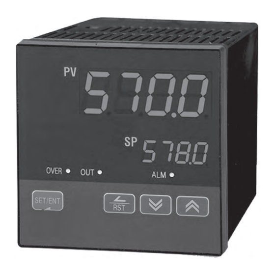
- Page 1 LIMIT CONTROLLER ® NOVA PD570 Series Instruction Manual PD570 & PD578 PRECISION DIGITAL CORPORATION GlobalTestSupply www. .com Find Quality Products Online at: sales@GlobalTestSupply.com...
- Page 2 Disclaimer The information contained in this document is subject to change without notice. Precision Digital Corporation makes no representations or warranties with respect to the contents hereof, and specifically disclaims any implied warranties of merchantability or fitness for a particular purpose.
-
Page 3: Table Of Contents
Table of Contents 1. Safety Guide and Specifications 1.1 Specifications 2. Front Panel Buttons and LED Indicators 3. Parameter Map 4. Operation Flow Chart 5. Controller Parameter Setup 5.1 Input Group (G.IN) 5.2 Control Group (G.CTL) 5.3 Alarm Group (G.ALM) 5.4 Retransmission Group (G.RET) 5.5 Communication Group (G.COM) 6. - Page 4 7.6 Grounding and Power Cable Connection 7.7 Signal Input Connection 7.8 Retransmission Output Connection (RET) 7.9 Relay Output Connection (RELAY) 7.10 Use of an External Relay 7.11 Communication Wiring (RS485) Appendix Table of D-Registers Tables and Figures Table 1: Universal Input Selection Table 2: Alarm Selection Fig 1: Temperature Bias Fig 2: Bias Formula Calculation...
-
Page 5: Safety Guide And Specifications
(6) Exposure to excessive moisture, electrical overloads, or mechanical vibration may damage the product. Limited Liability Precision Digital Corporation assumes no liability to any party for any loss or damage, direct or indirect, CAUTION caused by the use of or any unpredictable defect of the product. - Page 6 Operational Environment Precautions (1) Only operate the controller when it is properly installed. CAUTION (2) When installing the controller, select a location where: Rear terminals are protected from accidental contact. Mechanical vibrations are minimal. No corrosive gas is present. Temperature fluctuation is minimal. Temperature can be maintained between 10 and 50 ºC (50 and 110ºF) with 20 to 90% RH.
-
Page 7: Specifications
1.1 SPECIFICATIONS Except where noted all specifications apply to operation at 23ºC. General DISPLAY Dual 4 digits, red LED, -1999 to 9999 DIN Sizes PV Display SP Display Weight mm (inch) mm (inch) g (oz) 1/16 11.3 (0.45) 9.5 (0.37) 198 (7.0) 20.5 (0.81) 11.0 (0.43) 389 (13.7) FRONT PANEL... - Page 8 Process and Temperature Inputs TEMPERATURE DRIFT Refer to accuracy specifications below DECIMAL POINT Up to three decimal places for process inputs: 9.999, 99.99, 999.9, or 9999 REAR JUNCTION Automatic or off settings for temperature inputs. No user COMPENSATION calibration required. OFFSET ADJUSTMENT Four programmable input bias zones Open sensor indicated by PV display flashing S.
- Page 9 Relay Outputs RATINGS Out1: 250 VAC @ 3 A or 30 VDC @ 3 A (resistive load) Alarm: 250 VAC @ 1 A or 30 VDC @ 1 A (resistive load) ELECTRICAL NOISE A suppressor (snubber) should be connected to each SUPPRESSION relay contact switching inductive loads, to prevent disruption to the microprocessor's operation.
- Page 10 Retransmitting Output Retransmitting: 4 to 20 mA (600 Ω maximum) OUTPUT RANGE SCALING RANGE Any display range (see range for the input selected) ACCURACY +0.1% of full scale Serial Communications PROTOCOLS Modbus (ASCII, RTU), PC software, UNIT ADDRESS 1 to 99 (Max 31 units connected) BAUD RATE 600, 1200, 2400, 4800, 9600, 19200 bps, user selectable RESPONSE TIME...
-
Page 11: Front Panel Buttons And Led Indicators
2. Front Panel Buttons and LED Indicators OVER Control Keys Function Pressing SET/ENT key for at least 3 seconds switches between the operating display and SET/ENT the parameter setting display. This key is used to verify and bypass parameter settings (ENTER) when in the parameter group display. -
Page 12: Parameter Map
3. Parameter Map PwD: Lockout Password Use the arrows to enter the NOTE password and press the SET/ENT key. The default password is 0. S E T / E N T G.CTL G.IN G.ALM G.RET G.COM SET /ENT SET /ENT SET /ENT SET /ENT SET /ENT... -
Page 13: Operation Flow Chart
4. Operation Flow Chart Power On Operation Display Group Display PV Value When setting unit parameters, SP Value G.CTL G.IN should be set up prior to any other parameters. (note 1) ENT 3 Sec ON/OFF G.IN ENT key for 3 seconds or (note 2) no keystroke for 60 sec... -
Page 14: Controller Parameter Setup
5. Controller Parameter Setup 5.1 Input Group (G.IN) Press SET/ENT key to select input group. Press press key to cycle through G. I N groups as shown below. (Refer to parameter map in section 3.) G.CTL G.IN G.COM G.RET G.ALM Input group parameters should be established first, as changes to the input type may reset other parameter settings in other groups to their default value. - Page 15 This parameter sets the display temperature unit for ºC or ºF. IN-U Its default selection is ºC. Refer to Table 1 when changing the temperature unit for the temperature input range. This parameter sets the high limit of the temperature display range (maximum temperature IN.
-
Page 16: Fig 1: Temperature Bias
0ºC = BS4 -3ºC = BS3 -3ºC Original Temperature Temperature After Bias +1ºC = BS2 +1ºC -2ºC = BS1 -2ºC 0ºC = BS0 BSP1 BSP2 BSP3 0ºC 50ºC 75ºC 100ºC 25ºC Fig 1: Temperature Bias Example 1: The original temperature is shown within the range of 0ºC (Range Low) and 100ºC (Range High). Bias points have been used to adjust the displayed temperature as shown in the graph in Fig 1. - Page 17 Input Group Parameter Summary Display Parameter Setting Range Unit Default Remark Refer to Table 1: Universal Input Selection IN-T Input Type TC.K1 ºC / ºF ºC IN-U Display Unit T/C, RTD Max PV IN.RH Within sensor input range 1370 Display Range Refer to Table 1 Min PV IN.RL...
-
Page 18: Control Group (G.ctl)
5.2 Control Group (G.CTL) Press SET/ENT key to select control group. (Refer to parameter map in section 3.) G.CTL G.IN G.COM G.RET G.ALM This parameter establishes the set point for limit operation. This is the value set as the operating limit that will trigger the latching limit control relay. The parameter HI.LO sets if this is a high limit or a low limit. -
Page 19: Fig 3: Operation Of Limit Functions With O.act Set To Rev
This parameter sets the time units the controller uses for parameters with time components. This can be set to the format of HH.MM (hours.minutes) or MM.SS (minutes.seconds). Its default setting is HH.MM. This parameter resets most parameters to their factory settings. To reset the controller, set this parameter to ON. -
Page 20: Fig 5: Example Of Limit Control Relay Operation And Reset Function
5-2-1-2 Operation of Limit Functions when O.ACT = FWD, HI.LO = HIGH, R.MD = OFF The following illustration shows how each aspect of the limit control functions behave under over limit circumstances when O.ACT is set to FWD operation. 1. Power supplied to the controller. The limit control relay energizes. 2. - Page 21 5-2-2 Limit Status Display and Reset Functions The condition of the output can be seen by pressing the SET/ENT as shown in the Operation Flow Chart in section 4. The output status display refers to the condition of the limit control relay output. The output display has two conditions, OFF and ON.
- Page 22 Control Group Parameter Summary Setting Range Display Parameter Unit Default Remark AEU (0.0 to 100.0%) AEU (0.0%) Limit Set Point High or Low Limit HI, LO HI.LO Operation Selection R.MD Restart Relay Mode ON, OFF Reverse and O.ACT REV, FWD Forward Operation GEU (0.0 to 10.0%) GEU (0.5%)
-
Page 23: Alarm Group (G.alm)
5.3 Alarm Group (G.ALM) Press SET/ENT key to select alarm group. (Refer to parameter map in section 3.) G.CTL G.IN G.COM G.RET G.ALM The parameter to set the type of alarm to be set for alarm 1. The types of alarms selectable are shown in Table 3: Alarm Selection. The parameter to set the alarm trigger point for the alarm set in ALT1. -
Page 24: Fig 6: Alarm Operation
Table 3: Alarm Selection Operation Standby Alarm Type Display Data Absolute Value High Limit Alarm AH.F Absolute Value Low Limit Alarm AL.F High Limit Deviation Alarm DH.F Low Limit Deviation Alarm DL.F High Limit Deviation Alarm DH.R Low Limit Deviation Alarm DL.R High and Low Limit Deviation Alarm DO.F... - Page 25 Alarm Group Parameter Summary Setting Range Display Parameter Unit Default Remark ALT1 Alarm Type 1 Refer to Table 3: Alarm Selection AH.F Absolute AEU (-100.0 to 100.0%) AL-1 Set value of ALT1 EU (100.0%) Value Alarm High Deviation Deviation GEU (-100.0 to 100.0%) AL1.H EUS (0.0%) Limit of Alarm 1...
-
Page 26: Retransmission Group (G.ret)
5.4 Retransmission Group (G.RET) Press SET/ENT key to select retransmission group. (Refer to parameter map.) G.CTL G.IN G.COM G.RET G.ALM This parameter sets the type of retransmission mode to use. The setting options are PV, SP, and LPS. See notes below for an explanation of the retransmission types. The default setting is PV. -
Page 27: Communication Group (G.com)
5.5 Communication Group (G.COM) Press SET/ENT key to select communication group. (Refer to parameter map.) G.CTL G.IN G.COM G.RET G.ALM The parameter to select the type of communication protocol to be used. The parameter to set the communication speed (baud rate). The baud rate can be set at 600 to 19200 bps (bytes per second). - Page 28 Communication Group Parameter Summary Setting Range Display Parameter Unit Default Remark Communication PCC0, PCC1, Modbus ASCII, COM.P PCC0 Option Protocol Modbus RTU BAUD Baud Rate 600, 1200, 2400, 4800, 9600, 19200 9600 Option None, Even, Odd PRTY Parity None Option 1, 2 SBIT Stop Bit...
-
Page 29: Error Display And Correction
6. Error Display and Correction Error Message Error Incident Action Needed E.SYS EEPROM, Data Loss Needs Repair E.RJC RJC Sensor Failure Needs Repair SP Decimal Communication Failure Check Comm Cable Flashing S.OPN Open Sensor Detected Check Sensor GlobalTestSupply www. .com Find Quality Products Online at: sales@GlobalTestSupply.com... -
Page 30: Installation
7. Installation 7.1 Dimensions and Panel Cutouts PD578 1/4 DIN (3.78) (0.45) (3.92) (4.72) (3. 78XN) (3. 62) Units: (inch) - for reference only GlobalTestSupply www. .com Find Quality Products Online at: sales@GlobalTestSupply.com... - Page 31 PD570 1/16 DIN (0.43) (3.92) (1.89) (2.76) (1.89XN) (1.77) Units: (inch) - for reference only GlobalTestSupply www. .com Find Quality Products Online at: sales@GlobalTestSupply.com...
-
Page 32: Panel Mounting
7.2 Panel Mounting PD578 Mounting Bracket Panel PD570 Mounting Bracket Panel Installation Steps 1. Cut the mounting panel. (Refer to 7.1 Dimensions and Panel Cutouts) 2. Insert the controller through the front of the panel rear terminals first. 3. On applicable models, attach the right and left mounting bracket and secure it to the panel. 4. -
Page 33: Power Cable Specification
7.3 Power Cable Specification Make power connections using 0.9 to 2.0 mm or 16 AWG vinyl insulated wire. (Voltage rating of 300 VAC) 7.4 Terminal Specification Use M3.5 screw-compatible crimp on terminals with insulating sleeve as shown below. Minimum Diameter 3.0 mm (0.118 in) Maximum... -
Page 34: Terminal Assignment, Connections, And Ratings
7.5 Terminal Assignment, Connections, and Ratings PD578 Rating: 250 VAC @ 1 A Rating: 250 VAC @ 3 A 30 VDC @ 1 A 30 VDC @ 3 A Max: 19200 bps 100 - 240 VAC 50/60 Hz GlobalTestSupply www. .com Find Quality Products Online at: sales@GlobalTestSupply.com... - Page 35 PD570 Max: 19200 bps Rating: 250 VAC @ 3 A 30 VDC @ 3 A 100 - 240 VAC 50/60 Hz Rating: 250 VAC @ 1 A 30 VDC @ 1 A GlobalTestSupply www. .com Find Quality Products Online at: sales@GlobalTestSupply.com...
-
Page 36: Grounding And Power Cable Connection
7.6 Grounding and Power Cable Connection Use a thick grounding cable of at least 2 mm or 14 AWG and shorter than 20 m (approximately 22 ft) for class-3 grounding or better with a grounding resistance of less than 100 Ω . Be sure to ground from the grounding terminal to an independent grounding point. -
Page 37: Retransmission Output Connection (Ret)
7.8 Retransmission Output Connection (RET) To prevent electric shock, be sure to turn off power to the Nova Controller and the source circuit breaker before wiring. CAUTION Be sure to connect to correct polarities. Connecting to a wrong polarity may cause a controller malfunction. Use shielded wires for the wiring and connect independently to ground (1 point grounding). -
Page 38: Use Of An External Relay
7.10 Use of an External Relay Switching Inductive Loads When using switching inductive loads, the use of RC networks (snubbers) for AC loads or diodes for DC loads is recommended to prevent disrupting the microprocessor's operation. The suppressors also prolong the life of the relay contacts. -
Page 39: Communication Wiring (Rs485)
7.11 Communication Wiring (RS-485) Master Station NOVA Controller NOVA Controller RTX+ RTX+ RTX+ RTX- RTX- RTX- Terminating Resistor Terminating Resistor SHIELD Up to 31 slave controllers (Nova series controllers equipped with the RS-485 serial communication option) can be connected. Be sure to connect terminating resistors (220 Ω, 1/4 W) to slave and master controllers at communication channel ends as shown above. -
Page 40: Table Of D-Registers
Table of D-Registers: The following data registers are used to direct the US1 and US2 commands or for Modbus communication. PROCESS FUNCTION SET POINT SIGNAL ALARM IN/OUT ALT1 IN-T INT-U IN.RH IN.RL IN.DP AL-1 IN.SH IN.SL IN.FL NOWSTS SPRH A1DB BSP1 SPRL BSP2... - Page 41 PROCESS FUNCTION SET POINT SIGNAL ALARM IN/OUT RETH RETL COM.P BAUD PRTY SBIT DLEN ADDR RP.TM GlobalTestSupply www. .com Find Quality Products Online at: sales@GlobalTestSupply.com...
- Page 42 PROCESS FUNCTION SET POINT SIGNAL ALARM IN/OUT Read Only Location NOTE GlobalTestSupply www. .com Find Quality Products Online at: sales@GlobalTestSupply.com...
- Page 43 Notes Warranty and Return Information NOTE Precision Digital warrants this product to be free from material defects and workmanship under normal use and service for three years. Please contact Precision Digital Technical Support at (800) 610-5239 or e-mail at support@predig.com prior to any product return.
- Page 44 LIM570_D 10/15 GlobalTestSupply www. .com Find Quality Products Online at: sales@GlobalTestSupply.com...
Need help?
Do you have a question about the NOVA PD570 Series and is the answer not in the manual?
Questions and answers