
Related Manuals for Precision Digital Corporation CondoliDator 8


Summary of Contents for Precision Digital Corporation CondoliDator 8
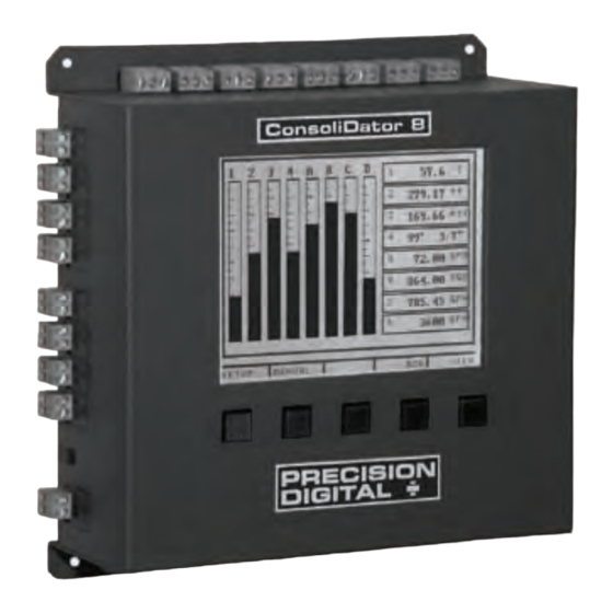
- Page 1 ® ConsoliDator Multi-Channel Controller Instruction Manual 1.800.561.8187 information@itm.com www. .com...
- Page 2 1.800.561.8187 information@itm.com www. .com...
- Page 3 INPUT EXTERNAL KEYPAD DIGITAL INPUTS OUTPUT ANALOG COMMON ANALOG ANALOG COMMON ANALOG OUTPUT 1 INTERNAL OUTPUT 2 OUTPUT 3 INTERNAL OUTPUT 4 POWER POWER INPUT GND/ GND/ GND/ GND/ ANALOG 5/ ANALOG 6/ ANALOG 7/ ANALOG 8/ FLOW 1 FLOW 2 FLOW 3 FLOW 4 INPUT...
- Page 4 1.800.561.8187 information@itm.com www. .com...
- Page 5 1.800.561.8187 information@itm.com www. .com...
- Page 6 1.800.561.8187 information@itm.com www. .com...
- Page 7 All functions operate down to -10°C (14°F.) LCD response is slower below 0°C (32°F) and may need contrast adjustment to be readable. 1.800.561.8187 information@itm.com www. .com...
- Page 8 1.800.561.8187 information@itm.com www. .com...
- Page 9 Supervisory, Summary and Annunciator Alarm Modes 1.800.561.8187 information@itm.com www. .com...
- Page 10 1.800.561.8187 information@itm.com www. .com...
- Page 11 WARNING Hazardous voltages present. Installation and service should be performed only by trained service personnel. 1.800.561.8187 information@itm.com www. .com...
- Page 12 1.800.561.8187 information@itm.com www. .com...
- Page 13 1.800.561.8187 information@itm.com www. .com...
- Page 14 CONNECT ONLY ONE OF THE POWER INPUTS 1.800.561.8187 information@itm.com www. .com...
- Page 15 1.800.561.8187 information@itm.com www. .com...
- Page 16 1.800.561.8187 information@itm.com www. .com...
- Page 17 Note: All inputs and outputs share a common ground. DO NOT power inputs and outputs with the same power supply. 1.800.561.8187 information@itm.com www. .com...
- Page 18 1.800.561.8187 information@itm.com www. .com...
- Page 19 1.800.561.8187 information@itm.com www. .com...
- Page 20 1.800.561.8187 information@itm.com www. .com...
- Page 21 1.800.561.8187 information@itm.com www. .com...
- Page 22 Inputs Outputs Channel #1 Alarm Relay #1 Channel #2 Alarm Relay #2 Channel #3 Alarm Relay #3 Channel #4 Alarm Relay #4 Channel #5 Alarm Relay #5 Channel #6 Alarm Relay #6 Channel #7 Alarm Relay #7 Channel #8 Alarm Relay #8 Flow Meter #1 Alarm Relay #9 Flow Meter #2...
- Page 23 1.800.561.8187 information@itm.com www. .com...
- Page 24 Analog Input: 1 Input Type: 4-20 mA Transmitter Function: NONE - Linear Channel ID: Analog 1 Configure Function Parameters Configure Sensor Input Sensor Configure Display Parameters Sensor: Value: 12.00 mA 12.000 mA Value Channel ID Configure Display Parameters Format Max Value Min Value Max Value Min Value.
- Page 25 Linear Square Root, Programmable Exponent, Integration Multi-Point Function High Value: Low Value: Sensor: Sensor: 1.800.561.8187 information@itm.com www. .com...
- Page 26 Configure Function Parameters. Low Value High Value: Low Value: Sensor: Sensor: 1.800.561.8187 information@itm.com www. .com...
- Page 27 Function Configure Function Parameters. Configure Function Parameters. Low Value High Value: Low Value: Sensor: Sensor: 1.800.561.8187 information@itm.com www. .com...
- Page 28 Function Function Configure Function Parameters. link link link Analog Input: 1 Analog Input: 1 Function Input Type: 4-20 mA Transmitter Configure Function Function: Summation Parameters Channel ID: Analog: 1 Function Setup Function Setup: Assign Channels: Channel = 1+2+3+4+5+6+7+8 Link: Analog Input: 1 Function Input Type: 4-20 mA Transmitter...
- Page 29 Analog Input Channels Channel Function Multi-Point Data Table. Configure Sensor Input Low Value High Value Sensor Sensor Sensor Sensor Low Value 1.800.561.8187 information@itm.com www. .com...
- Page 30 Flow Meter: 1 State: Channel ID: Flow: 1 ENABLED K Factor: 1000.00 pls / GAL Max Value: 50.00 GPM K-Fac Fmt: 9999.99 GPM Rate Fmt: 9999.99 GPM Total Fmt: 9999.99 GAL Units: GAL & GPM Inputs Display: RATE Channel ID Max Value Rate Fmt: Total Fmt...
- Page 31 Relays Alarm Mode Alarm Mode Alarm Mode Alarm Setup: 1 Alarm Mode: HIGH Channel: [1] Analog: 1 High Value: 16.00 mA Low Value: 8.00 mA Delay ON: Delay OFF: Alarm Mode Alarm Mode Channel High Value Low Value Delay ON Delay OFF 1.800.561.8187 information@itm.com...
- Page 32 Alarm Setup: 1 Alarm Mode: HIGH: Multi-Chan High Value: 160.0 GAL Low Value: 8.0 GAL Alarm Mode Delay ON: Delay OFF: Link Channels: Alarm Mode Channel High Value Low Value Delay ON Delay OFF Link Channels 1.800.561.8187 information@itm.com www. .com...
- Page 33 Alarm Mode Alarm Mode High Value Low Value Delay ON Delay OFF Pl. Width Pl. Delay Over Alarm Mode: Pl. Width Pl. Delay: 1.800.561.8187 information@itm.com www. .com...
- Page 34 Alarm Setup: 1 Alarm Mode: Trigger Channel: [A] Flow: 1 Set Point: 10.00 GAL Pl Width: Channel Set Point Pl. Width Alarm Setup: 1 Alarm Mode: ANNUNCIATOR: HIGH Channel: [A] Flow: 1 High Value: 16.00 GPM Low Value: 8.00 GPM Delay ON: Delay OFF: Alarm Mode...
- Page 35 Alarm Setup: 1 Alarm Mode: PLUNGER LIFT: DP Tubing Ch: [A] Flow: 1 Casing Ch: [2] Analog: 2 Switch Ch: [1] Reed SW: 1 Set Point: 100.00 GPM Alarm Mode Delay ON: After Flow: Tubing Ch Casing Ch Switch Ch Set Point Delay On After Flow...
- Page 36 Alarm Setup: 1 Alarm Mode: LEAD-LAG: HIGH Channel: TANK 1 High Value: 160.0 GAL Low Value: 8.0 GAL Delay ON: Delay OFF: Link Relays: Alarm Mode Alarm Mode Channel High Value Low Value Delay ON Delay OFF Link Relays 1.800.561.8187 information@itm.com www.
- Page 37 Lead-Lag Override: 1 Over Type: Override 1 & 2 ON Set Pt. #1: 170.0 GAL Set Pt. #2: 180.0 GAL Over Type Set Pt. #1 (#2, #3, #4) High Value Low Value Over Type Set Pt. #1 Set Pt. #2 1.800.561.8187 information@itm.com www.
- Page 38 Alarm Setup: 1 Alarm Mode: PWM: Linear Channel: [A] Flow: 1 100% Value: 16.00 GPM 0% Value: 8.00 GPM Cycle Time: Alarm Mode Channel 100% Value 0% Value Cycle Time 0% Value 100% Value 0% Value 100% Value 1.800.561.8187 information@itm.com www.
- Page 39 Alarm Setup: 1 Alarm Mode: PWM: PI Control Feedbk Ch: [A] Flow: 1 Set Point: 12.00 GPM Prop. Gain: 32.0 Int. Time: sec / rpt Cycle Time: Rly Period: Int. Limit: Inc / Dec: Increasing Set Point Feedbk Ch Prop. Gain Int.
- Page 40 Analog Output: 1 Mode: LINEAR Input Ch: [1] Analog: 1 Mode 4 mA Val: 10 gal 20 mA Val: 30 gal 4 mA Val 20 mA Val Input Ch 4 mA Val 20 mA Val Analog Output: 1 Mode: PID CONTROL Set-point: 8.00 mA Feedbk Ch:...
- Page 41 Relay Status: Hours Cycles Relay #1: ON 10.2 Relay #2: OFF 215.0 Relay #3: OFF 197.6 Relay #4: ON 175.2 Relay #5: OFF 121.7 Relay #6: OFF 255.1 Relay #7: ON 11.7 Relay #8: ON 143.6 Relay #9: OFF 412.5 Hours Cycles Supervisory,...
- Page 42 Supervisory, Summary Annunciator Alarm Rly: Low: High: 40.0 50.0 ON 20.0 ON Supervisory, Summary Annunciator Alarm 1.800.561.8187 information@itm.com www. .com...
- Page 43 300.0 Rly: Low: High: 40.0 50.0 ON Supervisory, Summary Annunciator Alarm Digital Inputs Reed SW: 1 Reed SW: 2 Reed SW: 3 Reed SW: 4 Supervisory, Summary Annunciator Alarm 1.800.561.8187 information@itm.com www. .com...
- Page 44 Analog Sensor Inputs: Tank 1 Tank 2 50.000 ft 40.000 ft 16.00 mA 12.00 mA Tank 3 Tank 4 30.000 ft 20.000 ft 8.00 mA 12.00 mA Tank 5 Tank 6 50.000 ft 40.000 ft 16.00 mA 12.00 mA Tank 7 Tank 8 30.000 ft 20.000 ft...
- Page 45 Hours Cycles Hours Cycles Rly: Low: High: 40.0 50.0 ON 20.0 ON 1.800.561.8187 information@itm.com www. .com...
- Page 46 1.800.561.8187 information@itm.com www. .com...
- Page 47 General Functions 1.800.561.8187 information@itm.com www. .com...
- Page 48 1.800.561.8187 information@itm.com www. .com...
- Page 49 1.800.561.8187 information@itm.com www. .com...
- Page 50 1.800.561.8187 information@itm.com www. .com...
- Page 51 1.800.561.8187 information@itm.com www. .com...
- Page 52 www.predig.com Modbus ID Modbus ID: 1. View All Channels real time real time 1.800.561.8187 information@itm.com www. .com...
- Page 53 Log Rate Log File Name import General Functions *.set 1.800.561.8187 information@itm.com www. .com...
- Page 54 1.800.561.8187 information@itm.com www. .com...
- Page 55 1.800.561.8187 information@itm.com www. .com...
- Page 56 1.800.561.8187 information@itm.com www. .com...
Need help?
Do you have a question about the CondoliDator 8 and is the answer not in the manual?
Questions and answers