Table of Contents
Advertisement
Quick Links
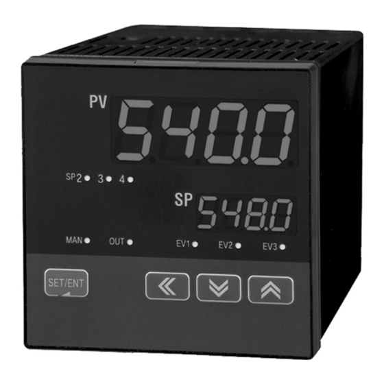
DIGITAL CONTROLLER
®
NOVA PD540 Series
Instruction Manual
O
r
d
e
r
f
r
o
m
:
C
A
B
r
i
g
g
s
C
o
m
p
a
n
y
PD540 - PD549
O
r
d
e
r
f
r
o
m
:
C
A
B
r
i
g
g
s
C
o
m
p
a
n
y
622 Mary Street; Suite 101; Warminster, PA 18974
Phone: 267-673-8117 - Fax: 267-673-8118
Sales@cabriggs.com
-
www.cabriggs.com
PRECISION DIGITAL CORPORATION
233 South Street
Hopkinton MA 01748 USA
Tel (800) 343-1001
Fax (508) 655-8990
1
Advertisement
Table of Contents

Related Manuals for Precision Digital Corporation NOVA PD540 Series


Summary of Contents for Precision Digital Corporation NOVA PD540 Series
- Page 1 DIGITAL CONTROLLER ® NOVA PD540 Series Instruction Manual PD540 - PD549 622 Mary Street; Suite 101; Warminster, PA 18974 Phone: 267-673-8117 - Fax: 267-673-8118 Sales@cabriggs.com www.cabriggs.com PRECISION DIGITAL CORPORATION 233 South Street Hopkinton MA 01748 USA Tel (800) 343-1001 Fax (508) 655-8990 ...
- Page 2 Disclaimer The information contained in this document is subject to change without notice. Precision Digital Corporation makes no representations or warranties with respect to the contents hereof, and specifically disclaims any implied warranties of merchantability or fitness for a particular purpose.
-
Page 3: Table Of Contents
PD540 Series Nova Digital Process and Temperature Controller Instruction Manual Table of Contents 1. Safety Guide and Specifications 1.1 Specifications 2. Front Panel Buttons and LED Indicators 3. Parameter Map 4. Operation Flow Chart 5. Controller Parameter Setup 5.1 Input Group (G.IN) 5.2 Output Group (G.OUT) 5.3 Control Group (G.CTL) 5.4 SP Group (G.SP) - Page 4 PD540 Series Nova Digital Process and Temperature Controller Instruction Manual 7.6 Grounding and Power Cable Connection 7.7 Signal Input Connection 7.8 Analog Output Connection 7.9 Relay Output Connection (RELAY) 7.10 Digital Input Connection (DI) 7.11 Use of an External Relay 7.12 Communication Wiring (RS-485) Appendix Table of D-Registers...
-
Page 5: Safety Guide And Specifications
(6) Exposure to excessive moisture, electrical overloads, or mechanical vibration may damage the product. Limited Liability Precision Digital Corporation assumes no liability to any party for any loss or damage, direct or indirect, CAUTION caused by the use of or any unpredictable defect of the product. - Page 6 PD540 Series Nova Digital Process and Temperature Controller Instruction Manual Operational Environment Precautions (1) Only operate the controller when it is properly installed. CAUTION (2) When installing the controller, select a location where: Rear terminals are protected from accidental contact. ...
-
Page 7: Specifications
PD540 Series Nova Digital Process and Temperature Controller Instruction Manual 1.1 SPECIFICATIONS Except where noted all specifications apply to operation at 23ºC. General DISPLAY Dual 4 digits, red LED, -1999 to 9999 DIN Sizes PV Display SP Display Weight mm (inch) mm (inch) g (oz) 1/16... - Page 8 PD540 Series Nova Digital Process and Temperature Controller Instruction Manual Process and Temperature Inputs TEMPERATURE DRIFT Refer to accuracy specifications below DECIMAL POINT Up to three decimal places for process inputs: 9.999, 99.99, 999.9, or 9999 REAR JUNCTION Automatic or off settings for temperature inputs. No user COMPENSATION calibration required.
- Page 9 PD540 Series Nova Digital Process and Temperature Controller Instruction Manual Relay Outputs RATINGS Out1: 250 VAC @ 3 A or 30 VDC @ 3 A (resistive load) Sub1, Sub2: 250 VAC @ 1 A or 30 VDC @ 1 A (resistive load) ELECTRICAL NOISE A suppressor (snubber) should be connected to each SUPPRESSION...
- Page 10 PD540 Series Nova Digital Process and Temperature Controller Instruction Manual Analog Outputs Continuous PID or retransmitting: 4-20 mA (600 Ω maximum) OUTPUT RANGE Time Proportional PID: 15 VDC pulse (600 Ω minimum, current limited at 30 mA) high, less than 0.1 VDC low, cycle time 1 to 300 seconds, user selectable SCALING RANGE Retransmitting 4-20 mA outputs can be scaled for any...
-
Page 11: Front Panel Buttons And Led Indicators
PD540 Series Nova Digital Process and Temperature Controller Instruction Manual 2. Front Panel Buttons and LED Indicators Control Keys Function Pressing SET/ENT key for at least 3 seconds switches between the operating display and SET/ENT parameter setup groups. This key is used to verify and bypass parameter settings in the (ENTER) parameter setup groups. -
Page 12: Parameter Map
PD540 Series Nova Digital Process and Temperature Controller Instruction Manual 3. Parameter Map PwD: Lockout Password Use the arrows to enter the NOTE password and press the SET/ENT key. The default password is 0. G.PID G.SP G.AT... - Page 13 PD540 Series Nova Digital Process and Temperature Controller Instruction Manual G.OUT G.ALM G.RET G.COM G.IN SET /ENT SET /ENT SET /ENT SET /ENT SET /ENT OUT1 ALT1 COM.P IN-T OUT2 HEAT COOL AL-1 RETH BAUD IN-U AL1.H RETL...
-
Page 14: Operation Flow Chart
PD540 Series Nova Digital Process and Temperature Controller Instruction Manual 4. Operation Flow Chart Power On Group display Operation Display When setting controller parameters, G.IN and G.OUT G.AT PV Display should be set up prior to any other ENT key for parameters. -
Page 15: Controller Parameter Setup
PD540 Series Nova Digital Process and Temperature Controller Instruction Manual 5. Controller Parameter Setup 5.1 Input Group (G.IN) Press SET/ENT key to select input group. Press press or key to cycle through G. I N groups as shown below. (Refer to parameter map in section 3.) ... - Page 16 PD540 Series Nova Digital Process and Temperature Controller Instruction Manual This parameter sets the display temperature unit for ºC or ºF. IN-U Its default selection is ºC. Refer to Table 1 when changing the temperature unit for the temperature input range. This parameter sets the high limit of the temperature display range (maximum temperature IN.
-
Page 17: Fig 1: Temperature Bias
PD540 Series Nova Digital Process and Temperature Controller Instruction Manual 0ºC = BS4 -3ºC = BS3 -3ºC Original Temperature Temperature After Bias +1ºC = BS2 +1ºC -2ºC = BS1 -2ºC 0ºC = BS0 BSP1 BSP2 BSP3 0ºC 25ºC 50ºC 75ºC 100ºC Fig 1: Temperature Bias Example 1:... - Page 18 PD540 Series Nova Digital Process and Temperature Controller Instruction Manual Input Group Parameter Summary Setting Range Display Parameter Unit Default Remark Refer to Table 1: Universal Input Selection IN-T Input Type TC.K1 ºC / ºF ºC IN-U Display Unit T/C, RTD Max PV IN.RH Within sensor input range...
-
Page 19: Output Group (G.out)
PD540 Series Nova Digital Process and Temperature Controller Instruction Manual 5.2 Output Group (G.OUT) Press SET/ENT key to select input group. (Refer to parameter map in section 3.) G. o UT G.AT ... -
Page 20: Fig 3: Time-Proportional Pid Control Output
PD540 Series Nova Digital Process and Temperature Controller Instruction Manual This parameter establishes reverse (REV) or forward (FWD) activation of the control o. A ct outputs. In forward operation, the control outputs will be most active when the PV value is higher than the SP, as the controller acts to lower the PV. - Page 21 PD540 Series Nova Digital Process and Temperature Controller Instruction Manual This parameter establishes the percent output transmitted by the control outputs when the controller is in STOP mode, or when an error condition occurs such as a PID algorithm error, A/D error, or open sensor error is detected. This parameter establishes the percent output transmitted by the COOL control outputs in a Heating &...
-
Page 22: Control Group (G.ctl)
PD540 Series Nova Digital Process and Temperature Controller Instruction Manual 5.3 Control Group (G.CTL) Press SET/ENT key to select control group. (Refer to parameter map in section 3.) g. c tl G.AT ... - Page 23 PD540 Series Nova Digital Process and Temperature Controller Instruction Manual This parameter establishes the operation of the digital input (DI) external contacts. The di. s l digital input operating configurations are shown in Table 2: DI Operation. This feature is only valid for models with digital inputs.
- Page 24 PD540 Series Nova Digital Process and Temperature Controller Instruction Manual Control Group Parameter Summary Setting Range Display Parameter Unit Default Remark Off (0.00) to 99.59 (hours.minutes) S-TM Start Time Delay Time Off (0.00) to 99.59 (hours.minutes) P-TM Process Run Time Time AUTO, MAN Automatic/Manual...
-
Page 25: Sp Group (G.sp)
PD540 Series Nova Digital Process and Temperature Controller Instruction Manual 5.4 SP Group (G.SP) Press SET/ENT key to select SP group. (Refer to parameter map in section 3.) g. s p G.AT ... - Page 26 PD540 Series Nova Digital Process and Temperature Controller Instruction Manual Set Point Group Parameter Summary Setting Range Display Parameter Unit Default Remark RUN, STOP Run/Stop RSP, SP1, SP2, SP3, SP4 SPSL SP Select AEU (Input AEU (0.0 - 100.0% of input range) Set Point 1 Range Low) AEU (Input...
-
Page 27: Pid Group (G.pid)
PD540 Series Nova Digital Process and Temperature Controller Instruction Manual 5.5 PID Group (G.PID) The PID group selection does not appear when the controller is operating in On/Off mode NOTE Press SET/ENT key to select PID group. (Refer to parameter map in section 3.) ... - Page 28 PD540 Series Nova Digital Process and Temperature Controller Instruction Manual This parameter sets the integration time for PID control. Setting ranges of 1.I are OFF or 1 to 6000 seconds. Its default setting is 120 seconds The parameter to set derivation time for PID control. Setting ranges of 1.D are OFF or 1 to 6000 seconds.
-
Page 29: Fig 6: Heating And Cooling Outputs Using Pid Control
PD540 Series Nova Digital Process and Temperature Controller Instruction Manual COOL HEAT (90%) (80%) Dead Band (1.DB at 20%) P/Pc = 4/5 Output OL-LIMIT OH-LIMIT (-5%) (100%) Fig 6: Heating and Cooling Outputs Using PID Control COOL HEAT (90%) Dead Band (1.DB at 20%) OUTPUT OL-LIMIT... -
Page 30: Fig 8: Heating Pid And Cooling On/Off Outputs
PD540 Series Nova Digital Process and Temperature Controller Instruction Manual COOL HEAT (90%) (20%) OUTPUT OL-LIMIT OH-LIMIT (0%) (105%) Fig 8: Heating PID and Cooling On/Off Outputs PID Group Parameter Summary Setting Range Display Parameter Unit Default Remarks Auto or 50.0 to 200.0% Anti-Reset Wind-Up Auto Differential of Deviation Value (d. -
Page 31: Auto-Tuning Group (G.at)
PD540 Series Nova Digital Process and Temperature Controller Instruction Manual 5.6 Auto-Tuning Group (G.AT) AT group selection does not appear if operating in On/Off mode or when set for manual output control. NOTE Press SET/ENT key to select AT group. (Refer to parameter map in section 3.) ... -
Page 32: Fig 10: Auto-Tuning Gain
PD540 Series Nova Digital Process and Temperature Controller Instruction Manual Auto-Tuning the Heating/Cooling Outputs: Auto-tuning of the heating/cooling outputs is the same process as the normal outputs. The PID heating/ cooling parameters will be calculated. The parameters for the PID derivation time (1.D) will be the same for both the heating and cooling outputs. -
Page 33: Alarm Group (G.alm)
PD540 Series Nova Digital Process and Temperature Controller Instruction Manual 5.7 Alarm Group (G.ALM) Press SET/ENT key to select alarm group. (Refer to parameter map in section 3.) G. a lm G.AT ... -
Page 34: Fig 11: Alarm Operation
PD540 Series Nova Digital Process and Temperature Controller Instruction Manual Table 3: Alarm Selection Operation Standby Alarm Type Display Data Absolute Value High Limit Alarm AH.F Absolute Value Low Limit Alarm AL.F High Limit Deviation Alarm DH.F ... - Page 35 PD540 Series Nova Digital Process and Temperature Controller Instruction Manual Alarm Group Parameter Summary Display Parameter Setting Range Unit Default Remark ALT1 Alarm Type 1 Refer to Table 3: Alarm Selection AH.F Set Value of Absolute AL-1 AEU (-100.0 to 00.0%) AEU (100.0%) Alarm 1 Value Alarm...
-
Page 36: Retransmission Group (G.ret)
PD540 Series Nova Digital Process and Temperature Controller Instruction Manual 5.8 Retransmission Group (G.RET) Press SET/ENT key to select retransmission group. (Refer to parameter map.) g. r et G.AT G.SP G.PID PWD G.CTL G.IN ... -
Page 37: Communication Group (G.com)
PD540 Series Nova Digital Process and Temperature Controller Instruction Manual 5.9 Communication Group (G.COM) Press SET/ENT key to select communication group. (Refer to parameter map.) G. c om G.AT G.SP G.PID PWD G.CTL G.IN ... - Page 38 PD540 Series Nova Digital Process and Temperature Controller Instruction Manual Communication Group Parameter Summary Setting Range Display Parameter Unit Default Remark PCC0, PCC1, Modbus ASCII, Communication COM.P Modbus RTU, Sync-Master, PCC0 Option Protocol Sync-Slave BAUD Baud Rate 600, 1200, 2400, 4800, 9600, 19200 9600 Option None, Even, Odd...
-
Page 39: Error Display And Correction
PD540 Series Nova Digital Process and Temperature Controller Instruction Manual 6. Error Display and Correction Error Message Error Incident Action Needed E.SYS EEPROM, Data Loss Needs Repair E.RJC RJC Sensor Failure Needs Repair SP Decimal Communication Failure Check Comm Cable Flashing S.OPN Open Sensor Detected... -
Page 40: Installation
PD540 Series Nova Digital Process and Temperature Controller Instruction Manual 7. Installation 7.1 Dimensions and Panel Cutouts PD548-PD549 1/4 DIN (3.78) (0.45) (3.92) (4.72) (3. 78XN) (3. 62) Units: (inch) - for reference only... - Page 41 PD540 Series Nova Digital Process and Temperature Controller Instruction Manual PD546-PD547 1/8 (V) DIN (0.45) (3.92) (1.89) (2.76) (1.89XN) (1.77) Units: (inch) - for reference only...
- Page 42 PD540 Series Nova Digital Process and Temperature Controller Instruction Manual PD544-PD545 3/16 DIN (0. 45) (3. 92) (2. 83) (3.54) (2.80XN) (2.68) Units: (inch) - for reference only...
- Page 43 PD540 Series Nova Digital Process and Temperature Controller Instruction Manual PD542-PD543 1/8 (H) DIN 9 9 .6 (3.78) (3.92) (0.45) (4.72) +0 .6 (3.62) Units: (inch) - for reference only...
- Page 44 PD540 Series Nova Digital Process and Temperature Controller Instruction Manual PD540-PD541 1/16 DIN (0.43) (3.92) (1.89) (2.76) (1.89XN) (1.77) Units: (inch) - for reference only...
-
Page 45: Panel Mounting
PD540 Series Nova Digital Process and Temperature Controller Instruction Manual 7.2 Panel Mounting PD548-PD549 PD544-PD545 PD546-PD547 Mounting Bracket Mounting Bracket Panel Panel PD542-PD543 PD540-PD541 Mounting Bracket Panel Mounting Bracket Panel Installation Steps 1. Cut the mounting panel. (Refer to 7.1 Dimensions and Panel Cutouts) 2. -
Page 46: Power Cable Specifications
PD540 Series Nova Digital Process and Temperature Controller Instruction Manual 7.3 Power Cable Specification Make power connections using 0.9 to 2.0 mm or 16 AWG vinyl insulated wire. (Voltage rating of 300 VAC) 7.4 Terminal Specification Use M3.5 screw-compatible crimp on terminals with insulating sleeve as shown below. Minimum Diameter 3.0 mm (0.118 in) -
Page 47: Terminal Assignment, Connections, And Ratings
PD540 Series Nova Digital Process and Temperature Controller Instruction Manual 7.5 Terminal Assignment, Connections, and Ratings PD548-PD549 Rating: 250 VAC @ 1 A 30 VDC @ 1 A Rating: 250 VAC @ 3 A 30 VDC @ 3 A Rating: 250 VAC @ 1 A 30 VDC @ 1 A 4 - 20 mADC or 15 VDC Voltage Pulse Max: 19200 bps... - Page 48 PD540 Series Nova Digital Process and Temperature Controller Instruction Manual PD546-PD547 Rating: 250 VAC @ 1 A 30 VDC @ 1 A Rating: 250 VAC @ 3 A 30 VDC @ 3 A Rating: 250 VAC @ 1 A 30 VDC @ 1 A 4 - 20 mADC or 15 VDC Voltage Pulse Max: 19200 bps Open circuit voltage:...
- Page 49 PD540 Series Nova Digital Process and Temperature Controller Instruction Manual PD544-PD545 NO switches (external excitation not required) or open collector transistor Open circuit voltage: approximately 5 VDC Logic levels: Lo = 0 to 0.8 VDC Hi = 4.7 to 28 VDC Rating: 250 VAC @ 3 A 30 VDC @ 3 A Rating: 250 VAC @ 1 A...
- Page 50 PD540 Series Nova Digital Process and Temperature Controller Instruction Manual PD542-PD543 4 - 20 mADC or 100 - 240 VAC 15 VDC Voltage Pulse 50/60 Hz Rating: 250 VAC @ 3 A 30 VDC @ 3 A NO switches (external excitation not required) or open collector transistor 2 0 19 18 17 16 15 14 13 12 11 Open circuit voltage:...
- Page 51 PD540 Series Nova Digital Process and Temperature Controller Instruction Manual PD540-PD541 NO switches (external excitation not required) or open collector transistor Open circuit voltage: approximately 5 VDC Logic levels: Lo = 0 to 0.8 VDC Hi = 4.7 to 28 VDC Max: 19200 bps Rating: 250 VAC @ 1 A 30 VDC @ 1 A...
-
Page 52: Grounding And Power Cable Connection
PD540 Series Nova Digital Process and Temperature Controller Instruction Manual 7.6 Grounding and Power Cable Connection Use a thick grounding cable of at least 2 mm or 14 AWG and shorter than 20 m (approximately 22 ft) for class-3 grounding or better with a grounding resistance of less than 100 Ω... -
Page 53: Analog Output Connection
PD540 Series Nova Digital Process and Temperature Controller Instruction Manual 7.8 Analog Output Connection To prevent electric shock, be sure to turn off power to the Nova Controller and the source circuit breaker before wiring. CAUTION Be sure to connect to correct polarities. Connecting to a wrong polarity may cause a controller malfunction. ... -
Page 54: Relay Output Connection (Relay)
PD540 Series Nova Digital Process and Temperature Controller Instruction Manual 7.9 Relay Output Connection (RELAY) Relay: NO - Normally Open Connection Relay: NC - Normally Closed Connection NOVA To prevent electric shock, be sure to turn off power to the Nova Controller and the source circuit breaker before wiring. -
Page 55: Communication Wiring (Rs-485)
PD540 Series Nova Digital Process and Temperature Controller Instruction Manual (1) DC External Relay External DC power Controller CAUTION Diode (Connect directly to the relay coil terminals) Relay (Verify relay coil ratings are less than the voltage and current ratings of the relay CAUTION contacts of the controller) (2) AC External Relay... -
Page 56: Table Of D-Registers
PD540 Series Nova Digital Process and Temperature Controller Instruction Manual Table of D-Registers: The following data registers are used to direct the US1 and US2 commands or for Modbus communication. PROCESS FUNCTION SET POINT SIGNAL ALARM IN/OUT SPSL ALT1 IN-T R-S,STOP/RUN ALT2 FUZZY... - Page 57 PD540 Series Nova Digital Process and Temperature Controller Instruction Manual PROCESS FUNCTION SET POINT SIGNAL ALARM IN/OUT 4.MR 4.Pc 4.Ic 4.Dc 4.DB HYS.H HYS.L RETH RETL COM.P BAUD PRTY SBIT DLEN ADDR RP.TM...
- Page 58 PD540 Series Nova Digital Process and Temperature Controller Instruction Manual PROCESS FUNCTION SET POINT SIGNAL ALARM IN/OUT Read Only Location NOTE...
- Page 59 PD540 Series Nova Digital Process and Temperature Controller Instruction Manual Notes Warranty and Return Information NOTE Precision Digital warrants this product to be free from material defects and workmanship under normal use and service for three years. Please contact Precision Digital Technical Support at (800) 610-5239 or e-mail at support@predig.com prior to any product return.
- Page 60 PD540 Series Nova Digital Process and Temperature Controller Instruction Manual How to Contact Precision Digital For Technical Support Call: (800) 610-5239 or (508) 655-7300 Fax: (508) 655-8990 Email: support@predig.com For Sales Support or to place an order please Call: (800) 343-1001 or (508) 655-7300 Fax: (508) 655-8990 Email: sales@predig.com...
Need help?
Do you have a question about the NOVA PD540 Series and is the answer not in the manual?
Questions and answers