Raven SCS 660 Installation And Service Manual
Hide thumbs
Also See for SCS 660:
- Installation & service manual (60 pages) ,
- Installation manual (13 pages) ,
- Programming (14 pages)
Table of Contents
Advertisement
Quick Links
Advertisement
Table of Contents

Related Manuals for Raven SCS 660


Summary of Contents for Raven SCS 660
- Page 1 SCS 660 FOR GRANULAR APPLICATIONS INSTALLATION SERVICE MANUAL...
-
Page 3: Table Of Contents
SYMBOL DEFINITION ............................. 2 INTRODUCTION ..............................3 INSTALLATION ................................. 4 1. MOUNTING THE RAVEN RADAR SPEED SENSOR ........4 2. MOUNTING THE ENCODER ............. 5 3. MOUNTING THE HYDRAULIC CONTROL VALVE ........6 4. MOUNTING THE CONSOLE AND CABLING ......... 7 BATTERY CONNECTIONS ............................ -
Page 4: Symbol Definition
SYMBOL DEFINITION - Kilometers - Pounds per minute km/h - Kilometers per hour kg/min - Kilograms per minute - Volume per acre - Pounds per acre - Volume per hectare kg/ha - Kilograms per hectare - Volume per 1,000 sq. ft. - Pounds per 1,000 sq. -
Page 5: Introduction
This manual provides a simple step-by-step procedure for installing and operating. The SCS 660 consists of a Control Console, a Speed Sensor, an Encoder, and a Hydraulic Control Valve. The Console mounts directly in the cab of the vehicle for easy operator use. -
Page 6: Installation
INSTALLATION MOUNTING THE RAVEN RADAR SPEED SENSOR See Appendix 8 for Wheel Drive Speed Sensor installation instructions. See Appendix 9 for Speedometer Drive Speed Sensor installation instructions. For mounting the Radar, the following guidelines will assure proper installation: It is suggested that a large heavy mounting bracket, (P/N 107-0159-693) be attached to the vehicle frame for mounting the Radar. -
Page 7: Mounting The Encoder
MOUNTING THE ENCODER Mount Encoder on output shaft of conveyor, or other shaft which rotates at a known ratio to the conveyor. (See Figures 5,6,7,& 8). Apply grease to Encoder shaft, conveyor shaft, and Encoder coupler (fits 1" diameter conveyor shaft). Secure coupler to Encoder and conveyor shafts with set screws provided. -
Page 8: Mounting The Hydraulic Control Valve
MOUNTING THE HYDRAULIC CONTROL VALVE Refer to Figures 5,6,7,& 8 for typical placement of the Hydraulic Control Valve. Valve is to be mounted with motor in the upright position. SPINNER SYSTEM OPEN HYDRAULIC SYSTEM (FIXED DISP. PUMP) CLOSED HYDRAULIC SYSTEM (VARIABLE DISP. PUMP) FIGURE 5 FIGURE 6 PNEUMATIC SYSTEM... -
Page 9: Mounting The Console And Cabling
MOUNTING THE CONSOLE AND CABLING Mount the Console and Switch Box to a secure support inside the cab of the vehicle. Connect the Console Control Cable to the plug in the back of the Console. (See Figure 9). Route the Console Control Cable out of the vehicle cab and connect with Flow Control Cable. -
Page 10: Battery Connections
BATTERY CONNECTIONS FIGURE 10... -
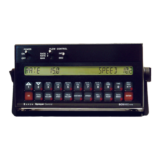
Page 11: Console Features
CONSOLE FEATURES IMPORTANT: This Console requires selection of US (acres), SI [hectares], or TU {1,000 sq. ft.} area; SP1 (wheel drive, etc.) or SP2 (radar) speed sensor; LI (liquid sprayer), GR1 (single bed belt), or GR2 (split bed belt); and C-Sd (Standard Valve), C-F (Fast Valve), and C-FC (Fast Close Valve). -
Page 12: Console Calibration
CONSOLE CALIBRATION CALCULATING "BOOM CAL" Enter the total width of the spread pattern in inches [cm] as boom length (See "Definition of Boom Calibration keys"). CALCULATING "SPEED CAL" Initial SPEED CAL is 598 [152]. Complete Steps 1 thru 6 to refine this number after section "INITIAL CONSOLE PROGRAMMING"... -
Page 13: Calculating "Spreader Constant
CALCULATING "SPREADER CONSTANT" For RATE displayed in 1 lb [1 kg] increments: = Length in inches [centimeters], of belt travel per 1 revolution of Encoder = Gate Height in inches [centimeters] = Gate Width in inches [centimeters] English (US) : Metric (SI): Spreader Constant = 311,040 Spreader Constant = [18,000,000]... -
Page 14: Calculating "Valve Cal
CALCULATING "VALVE CAL" The initial Control Valve calibration number is 2123 for C-Sd, or 743 for C-FC. After operating the system, you may desire to refine this number. See definitions below: For STANDARD VALVE (C-Sd): For FAST VALVE (C-F or C-FC): Valve Backlash Digit Controls the time of the first correction pulse after a change in correction direction is detected. -
Page 15: Console Programming
CONSOLE PROGRAMMING When entering data into the Console, the entry sequence is always the same. NOTE: DATA MUST BE ENTERED IN KEYS 3 THRU 8. Depress the key in which Depress the ENTER key. you wish to enter data. "E" will illuminate in the DATA display. -
Page 16: Initial Console Programming
INITIAL CONSOLE PROGRAMMING When you first turn on Console power, after all installation procedures have been completed, the Console will flash "CAL" in the RATE display. This means you must "calibrate", or program, the Console before it can be operated. This is a one- time operation which does not have to be repeated. - Page 17 Selecting LI, GR1, or GR2. To select GR1, or GR2, step until desired code is displayed in the DATA display. NOTE: If a liquid application (LI) is desired, see the SCS 660 Liquid Application Manual. Momentarily depress The data display will now display C-Sd.
- Page 18 Definition of Boom Calibration keys. Depressing this key displays selected boom number in DATA display. EXAMPLE: Left Boom will be displayed as b-01, and Right Boom will be displayed as b-02. Depressing this key after selecting BOOM CAL changes the boom number. EXAMPLE: b-01 will change to b-02.
- Page 19 Enter RATE 1 CAL (lbs/acre) [Kg/ha] target application rate in key labelled Enter RATE 2 CAL (lbs/acre) [Kg/ha] target application rate in key labelled (If you do not use a second rate, enter the same rate as RATE 1 CAL). YOU HAVE NOW COMPLETED PROGRAMMING THE CONSOLE The flashing "CAL"...
- Page 20 Enter TIME Select TIME Enter TIME when RATE display shows "TInE". NOTE: This is a 24 hour clock. Therefore, all time after 12:59 p.m., add 12 hours. Thus, 8:30 a.m. is entered as 8:30, but 1:30 p.m. is entered as 13:30 in the keyboard.
-
Page 21: Other Display Features
OTHER DISPLAY FEATURES To display TOTAL AREA covered, depress key labelled To "zero out" this total at any time, enter a "0" in this key. To display TOTAL VOLUME (pounds)[kg] covered, depress key labelled To "zero out" this total at any time, enter a "0" in this key. IMPORTANT: Both RATE and DATA displays windows are used to enter and view volume totals. -
Page 22: Self Test Feature
SELF TEST FEATURE SELF TEST allows speed simulation for testing the system while the vehicle is not moving. Enter the simulated operating speed in the key labelled If 6 MPH [9.6 km/h] is desired, enter 6.0 [9.6] (See CONSOLE PROGRAMMING). Verify SPEED by depressing key labelled 6.0 [9.6] will appear in the DATA display. -
Page 23: Automatic Rate
AUTOMATIC RATE +/- This feature sets the increment at which flow is increased or decreased in RATE 1 or RATE 2 operation. Enter rate change value by depressing key labelled until DATA display flashes. To enter a value depress then the increment value, and EXAMPLE: If rate is to change by "1": Enter a value of 1 for RATE +/-. -
Page 24: 11. Enter Mode Sequence With Activated Data-Lock
11. ENTER MODE SEQUENCE WITH ACTIVATED DATA-LOCK The DATA-LOCK feature prohibits the entry of data without first entering the DATA- LOCK CODE. If DATA-LOCK is not desired, omit Steps 9, 10, and 11. Depress the key into which you wish to enter data. Depress CODE message will appear. - Page 25 (Serial interface console only). FILE GPS FILE REFERENCE Used only with Raven Grid Application System. See Grid Application System manual for more details (Serial inter- face console only). InAC GPS OPTIONS Used only with Raven Grid Application System.
- Page 26 DISPLAY RATE DATA FEATURE and DESCRIPTION UniT DATA LOGGER TRIGGER UNITS Used in data logging mode. The trigger unit is selectable between feet [meters] or seconds (Serial interface console only). dLoG DATA LOGGER ON/OFF Turns data logger ON or OFF (Serial interface console only). Definition of Data Menu Key: Depressing this key displays selected Data Menu features in RATE display.
- Page 27 DISPLAY SMOOTHING ON/OFF RATE display will show "diSP". DATA display will show "on". Depressing momentarily changes the DATA display between "on" and "oFF". A value of "on" means smoothing is enabled; a value of "oFF" means smoothing is disabled. The percent smoothing is determined by the third digit of VALVE CAL value as shown: Brake Point Digit...
- Page 28 BIN LEVEL FAULT ON/OFF RATE display will show "bin". DATA display will show "oFF". Depressing momentarily changes the DATA display between "oFF" and "on". A value of "on" means fault detector is enabled; a value of "off" means fault detector is disabled. Momentarily depress to advance to FAN CALIBRATION.
- Page 29 BAUD RATE RATE display will show "bAUd". DATA display will show "1200". Depressing momentarily changes the DATA display between "1200" and "9600". Momentarily depress to advance to DATA LOGGER TRIGGER VALUE. DATA LOGGER TRIGGER VALUE RATE display will show "TriG". DATA display will show "0".
- Page 30 DATA LOGGER ON/OFF The DATA LOGGER uses the communications strings listed in Appendix 6 to pass data out through the serial port. The data is sent at a set time interval or a set distance traveled, as determined by the values entered in the DATA LOGGER TRIGGER VALUE and DATA LOGGER TRIGGER UNITS.
-
Page 31: 13. Decimal Shift
13. DECIMAL SHIFT The DECIMAL SHIFT feature is used to increase system accuracy at low application rates. Shifting of the decimal point is done during the entry of METER CAL. After entering METER CAL mode, depress the decimal shift key labelled , enter the meter calibration constant number, and depress . -
Page 32: Initial System Set-Up
INITIAL SYSTEM SET-UP With NO product in bin. Place boom ON/OFF switches to OFF. Place RATE 1/RATE 2/MAN switch to MAN. Place POWER ON/OFF switch to ON. Verify correct Boom Widths, SPEED CAL, METER CAL, VALVE CAL, and RATE CALS have been entered in the Console. -
Page 33: Troubleshooting Guide
TROUBLESHOOTING GUIDE PROBLEM CORRECTIVE ACTION 1) NO DISPLAY LIGHTS WITH POWER ON. 1) Check fuse on back of Console. 2) Check battery connections. 3) Check operation of POWER ON/OFF switch. 4) Return Console to your Dealer to replace Processor Board Assembly. 2) ALL KEYBOARD LIGHTS ON AT SAME 1) Return Console to your dealer to TIME. - Page 34 12) RATE READS "0000". 1) Verify SPEED is registering accurately. If SPEED is zero, refer to Troubleshooting Problem 2) Verify TOTAL VOLUME is registering flow. If not, refer to Troubleshooting Problem 15. 3) Enter a typical speed in SELF TEST. With BOOM 1 and MASTER ON, verify AREA/HOUR is registering.
-
Page 35: Appendixes
APPENDIX 1 WHEEL DRIVE SPEED SENSOR INSTALLATION AND CALIBRATION PROCEDURE MOUNTING WHEEL DRIVE SPEED SENSOR The Wheel Drive Speed Sensor consists of four magnets, a switch assembly with cable, and mounting hardware. Sequence of mounting Speed Sensor: Select a non-driven wheel (left front tractor wheel or implement wheel). Check for predrilled holes in rim. -
Page 36: Procedure To Test Encoder Cables
RIM DRILLING INSTRUCTIONS FOR WHEEL DRIVE SPEED SENSOR MAGNETS On wheels which do not have pre-punched mounting holes, proceed as follows: RIMS WITH FOUR OR EIGHT HOLE STUD PATTERN: Choose stud holes that are opposite each other as shown below. Using the center of opposite holes, scribe two lines on the rim web to divide the circumference into four equal parts. -
Page 37: Fan Rpm Sensor Installation
CALCULATING "SPEED CAL" Place a chalk mark or tape onto the vehicle tire that the Speed Sensor mounted to it as shown below. Mark the initial spot on the ground. Drive vehicle straight ahead counting 10 full revolutions of the wheel. The mark must stop at the same position it was in when the vehicle started. -
Page 38: Bin Level Sensor Installation
APPENDIX 2 SPEEDOMETER DRIVE SPEED SENSOR INSTALLATION AND CALIBRATION PROCEDURE MOUNTING THE SPEEDOMETER DRIVE SPEED SENSOR Remove the existing speedometer cable from the back of the vehicle speedometer. Pull cable through fire wall into engine compartment. Install adapter and key on speedometer cable and connect to Transducer Assembly. (Some units do not use adapter and key). - Page 39 CALCULATING "SPEED CAL" Complete "INITIAL CONSOLE PROGRAMMING" before doing this procedure. Enter “0” in key labelled Enter a SPEED CAL of 612 [155] in key labelled Drive 1 mile [1 km]. CAUTION: Do not use vehicle odometer to determine distance. Use section lines or Highway markers.
- Page 40 APPENDIX 3 PROCEDURE TO TEST SPEED SENSOR EXTENSION CABLES Verify that the Console is in the SP1 Speed Sensor mode while testing the cable. Disconnect extension cable from Speed Sensor Assembly cable. Hold extension cable connector so that keyway is pointing in the 12 o’clock position. PIN DESIGNATIONS 2 o’clock socket location is power.
-
Page 41: Verification Of Spreader Constant
APPENDIX 4 PROCEDURE TO TEST FLOW METER CABLES Disconnect cable from Flow Sensor. Hold Flow Sensor cable so that the keyway is pointing in the 12 o’clock position: PIN DESIGNATIONS 2 o’clock socket location is ground. 10 o’clock socket location is power. 6 o’clock socket location is signal. -
Page 42: Wheel Drive Speed Sensor Installation
APPENDIX 5 VERIFICATION OF SPREADER CONSTANT To verify and refine the Spreader Constant, perform the following procedure (after completing INITIAL CONSOLE PROGRAMMING): Weigh loaded truck and note weight. Enter the Product Density in lbs/cu.ft. [grams/liter] into key labelled Enter a "0" into the key labelled With the rate switch in the MAN position, unload a portion of the load by positioning the boom switch to ON. - Page 43 C-NL1 for "Hall Effect" control valve. C-NL2 for "Reed Switch" control valve. The rest of the console calibration is the same as described in the SCS 660 GRANULAR APPLICATION manual. (BOOM CAL, SPEED CAL, METER CAL, SPREADER CONSTANT [starting values below], VALVE CAL, RATE 1 CAL, and RATE 2 CAL).
- Page 44 APPENDIX 7 FAN RPM SENSOR INSTALLATION 117-0159-575 Assemble Fan Sensor to fan sensor bracket with stainless steel bolt, lock washer, and nut. Assemble fan sensor bracket to fan sensor mounting tab on box with stainless steel bolt, lock washer, and nut. (See Figure above).
-
Page 45: Speedometer Drive Speed Sensor Installation
APPENDIX 8 BIN LEVEL SENSOR INSTALLATION 063-0171-252 Install Bin Level Sensor in spreader bin at location illustrated. Select location in accordance to bin construction. Use the mounting plate as a template to mark the location for the holes. Drill and deburr all holes. -
Page 46: Serial Interface
Line Feed Communication Carriage Return string RATE 1 Rate Cal = 123.4 Decimal point is not sent from Remote Computer to Raven Console. Optional 9 pin to 9 pin cable pinout (P/N 115-0159-822). DSR 6 CTS 8 RAVEN COMPUTER/ DTR 4... -
Page 47: Scs 660 Communication Strings
SCS 660 CONSOLE TO REMOTE COMPUTER All console output strings begin with $R040C, the $R indicates a Raven communication string, the 040 is the last three digits of the current SCS 660 programmed chip part number and C is the software revision number. - Page 51 Bring the defective part, and proof of date of purchase, to your local dealer. If your dealer agrees with the warranty claim, he will send the part, and proof of purchase to his distributor or to Raven for final approval.
- Page 52 Manual Rev. E, SCS 660, 9-97 Order: 50,9-11-97, #016-0159-572...
Need help?
Do you have a question about the SCS 660 and is the answer not in the manual?
Questions and answers