
Related Manuals for Raven SCS 4000


Summarization of Contents
Important Safety Information
Safety Information
Read manual and safety instructions carefully before installing the SCS 4000/5000 Series console.
Hydraulic Safety
Recommendations for working on hydraulic systems, including precautions for hot fluid and maintenance.
Electrical Safety
Guidelines for safe electrical connections, including polarity and disconnecting for welding/jump-starting.
Introduction
Sprayer & Spreader Control Systems
Overview of SCS 4000/5000 Series systems for application uniformity and product coverage.
System Components
Description of components for SCS 4000/5000, 4070, and 4400/4600 control systems.
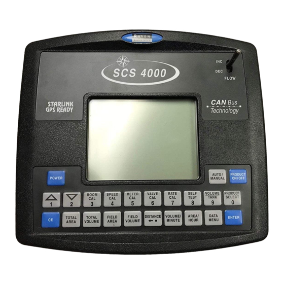
SCS 4000/5000 Series Console Feature Overview
Details on the display area and keypad features of the SCS 4000/5000 Series consoles.
Care and Use
Guidelines for proper mounting, cable routing, and environmental considerations for the SCS console.
Technical Specifications
Specifications including dimensions, weight, environmental limits, power, and ports for the SCS console.
Updates
Information on obtaining manual and software updates for Raven consoles from the website.
CAN Networking and CAN Data Menu
Detecting CAN Nodes
Ensuring the SCS console communicates with CANbus nodes for correct product application.
Readdressing the Nodes
Procedure to reconfigure product control node order if the SCS console cannot detect nodes.
Programming CANbus Nodes
Information on programming CAN product nodes using the SCS console in Edit mode.
CAN Troubleshooting
Troubleshooting techniques for CAN systems, applicable to flow/speed sensors and control/boom valves.
CAN Node Off-line Errors
Common causes for losing CAN communication between the console and nodes.
Installation
Install the SCS Console
Requirements for selecting a mounting location for the SCS console inside the machine cabin.
Mount the SCS Console
Instructions for mounting the SCS console using the provided plate and clamps.
Cable and Power Connections
Procedures for connecting the console cable and routing power connections.
Calibration Reference Sheet
Edit Mode
How to enter Edit mode to program numerical values into the SCS console.
Initial Startup & Console Programming
Reset Console Memory
Procedure to reset the SCS console's internal memory to return to initial programming screens.
Initial Calibration Sequence
Steps for initial console setup including contrast, units, and product control type.
Units
Setting the measurement units for the SCS console (US Acres, SI Hectares, etc.).
Product Control Type
Selecting the type of product control (Liquid, Granular, Spinner, NH3) for the SCS console.
Valve Type
Selecting the appropriate valve type for the SCS console's control system.
Spreader Constant (Granular Applications)
Inputting the spreader constant value for granular applications.
Product Density (Granular Applications)
Inputting the product density value for granular applications.
Meter Cal (Liquid Applications)
Inputting the meter calibration value for liquid product application.
Fan Speed Cal (Spinner Applications)
Inputting the fan speed calibration value for spinner applications.
Valve Cal
Programming the valve calibration value to adjust control valve response.
Rate Cal
Entering the target application rate for product application.
Speed Sensor Type
Selecting the type of speed sensor used (Wheel Speed or Radar).
Speed Cal
Initial speed calibration values and procedure for the SCS console.
Boom Cal
Inputting boom section widths for calibration in the SCS console.
Reprogramming Initial Settings
Procedure to change initial console programming settings after initial setup.
Console Programming
Overview of how to program the SCS console using calibration keys.
Edit Mode
How to enter Edit mode to program numerical values into the SCS console.
Calibration Keys
Using calibration keys to program and calibrate the SCS console.
Self Test
Performing a self-test to check or troubleshoot the product control system.
Function Keys
Using function keys to display application information and test the system.
Volume/Minute
Displays current volume per minute or flow rate.
Area/Hour
Estimates the area that could be covered based on current speed and boom operation.
Data Menu
Accessing the SCS Data Menu for console settings and features.
Product On/Off
Toggles product control on or off.
Tank Volume
Displays current volume remaining in the tank or bin.
Product Select
Toggles product selection on the controller for viewing data or changing settings.
Self Test Mode
Simulates speed for testing the system while the vehicle is not moving.
Decimal Shift
Feature to increase system accuracy at low application rates by shifting decimal places.
Data Menu
Serial Submenu
Options for serial communication, data logging, and field reference.
Data Logger (4400 and 4600 Only)
Enabling/disabling data logging and saving information to a compact flash card.
Field Reference
Entering a reference number to represent a job for data logging.
GPS Baud Rate
Setting the baud rate for communication with a connected GPS receiver.
Serial Baud Rate
Selecting baud rate for serial port communication.
Variable Rate Change Alarm
Enabling or disabling alarms for variable rate changes.
Trigger Value
Determining how often data is sent to the serial port for data logging.
Trigger Units
Selecting trigger units (feet, meters, or seconds) for data logging.
Additional Serial Options
Options for print field data or data direction for SCS 4400/4600.
Product Submenu
Settings related to product control, including boom selection and PWM offsets.
Boom Select
Assigning products to individual boom sections for application.
Off Rate %
Acceptable percentage deviation of actual rate from target rate.
PWM High Offset
Setting the maximum desired RPM or hydraulic output for a PWM control valve.
PWM Low Offset
Setting the minimum RPM or hydraulic output for a PWM control valve.
PWM Frequency
Setting the coil frequency for PWM valves.
Preset PWM Offset (PWM Valves Only)
Setting an initial pulse width for PWM-Close mode valves.
Standby Pressure (PWM Valves Only)
Setting target pressure for liquid systems in standby condition.
Rate Bump Delta
Setting the increment for rate adjustments using the INC/DEC switch.
Low Flow Limit
Setting a limit for volume/minute to activate low flow limit and alarm.
Low Tank
Setting a level for tank volume to activate the low level alarm.
Valve Delay
Setting the delay between console controlling flow rate after booms are turned on.
Spreader Constant
Setting the spreader constant, should be zero for liquid products.
Valve Cal 2
Fine-tuning control valve response and application rate oscillations in PWM mode.
Pump Cal/Fan Cal
Setting pulses per revolution for pump/fan RPM readout.
Dual Sensor Alarm %
Tolerance setting for flow switch monitor and flow readings.
Vacuum or Bin Level Alarm
Enabling or disabling vacuum or bin level alarms.
Flow Switch Alarm (Chemical Injection Unit)
Enabling or disabling flow switch alarm for chemical injection.
Valve Advance (Standard or Fast Valve)
Setting time for valve opening when booms are turned off in automatic mode.
Pressure
Displays current PSI, kPa, or BAR.
Pressure 1 Cal
Calibrating pressure transducer #1.
Pressure 2 Cal
Calibrating pressure transducer #2.
Agitator
Enabling or disabling the agitator output.
PWM Output
Indicating the output status of a PWM valve.
VLV STATUS (when not programmed in PWM mode)
Displays current status of the control valve.
Standby (Pressure) Enable (PWM Valves Only)
Enabling standby pressure setting for liquid application systems.
Low Pressure Limit
Setting a minimum pressure for liquid application systems.
Dual Loop Control (PWM Valves Only)
Feature for low application rates using flow meter and pressure transducer.
Auto Calibration (PWM Valves Only)
Automatically calibrating high and low offset values for PWM control valves.
Console Submenu
Settings for console contrast, alarms, display smoothing, and data lock.
Contrast
Adjusting screen contrast for readability.
Audible Alarm
Toggling the audible alarm on or off.
Display Smoothing
Smoothing the rate displayed during product applications.
Time, Month, Day, and Year
Setting the current date and time for the console.
Days Wait
Setting days before console enters low power mode and loses time settings.
Data Lock
Prohibiting calibration value entry without a data lock code.
PGM REV Update
Displaying SCS console software program and revision level.
Ratio Rate
Enabling or disabling ratio rate application mode for multiple products.
CAN Submenu
Status indicators for CAN nodes like boom sense, AutoBoom, and product control nodes.
Boom Sense and Speed Node
Indicates status of boom sense/speed node.
Speed Signal Source (SCS 4070 Only)
Toggling speed signal source between Console and Speed/AccuBoom node.
AutoBoom Control Node
Indicates status of AutoBoom control node.
Product Control Node 1
Indicates status of CAN product control node #1.
Product Control Node 2
Indicates status of CAN product control node #2.
Product Control Node 3
Indicates status of CAN product control node #3.
Product Control Node 4
Indicates status of CAN product control node #4.
Product Control Node 5
Indicates status of CAN product control node #5.
Row Sense Node
Indicates status of a row sense node.
Readdress Control Nodes
Reconfigure product control node order.
AccuBoom Control Node
Indicates status of AccuBoom control node.
Calibration Summary
Review current values and settings for each configured product control channel.
Data Logger (4400 and 4600 Only)
Saves on-the-go application info to flash card for PC transfer.
Setup
Setup procedures for data logging system, including trigger value and GPS baud rate.
Console Calibration
Speed Cal
Recommended initial speed calibration values and procedure.
Wheel Drive Speed Sensor
Procedure for calibrating the wheel drive speed sensor.
Adjusting for Additional Magnets
Adjusting speed calibration for additional magnets on the wheel drive sensor.
Speedometer Drive Speed Sensor
Procedure for calibrating the speedometer drive speed sensor.
Liquid Applications
Calibration procedures for liquid sprayers.
Boom Cal
Inputting boom section widths for calibration.
Band Spraying Adjustment
Calculating the Adjusted Applied Rate for band spraying.
Meter Cal
Flow meter calibration number found on the flow meter tag.
Valve Cal
Programming valve calibration number to adjust control valve response time.
Rate Cal
Programming the target application rate.
SCS Multi-Tier Features
Accessing features for multi-tier plumbing systems.
Tier 1 High Volume per Minute
Sets maximum allowed volume per minute before the second tier is enabled.
Tier 2 High Volume per Minute
Selects max allowed volume per minute before tiers 1 and 2 are enabled.
Percent Tier Disable
Percentage factor to disable the higher tier based on volume settings.
Dual Loop Control Mode Settings
Settings for dual loop control feature using flow meter and pressure transducer.
Flow Cal
Sets system response to rate control inputs while product is flowing.
System (Pressure) Gain
Adjusting system aggressiveness for pressure response.
Granular Applications
Calibration procedures for granular applications.
Spreader Constant
Calculating and verifying the spreader constant for granular applications.
Standard Rate display
Formula to calculate spreader constant for rates in 1 pound increments.
Metric Rate Display
Formula to calculate spreader constant for rates in 1 kg increments.
Verification of Spreader Constant
Procedure to verify and refine the spreader constant.
Product Density
Entering product density for spreader constant calculations.
Spinner RPM
Calibrating spinner speed control using a CAN control node.
Additional Calibration Data
Programming data through the VOLUME/TANK key.
Entering Tank Volume
Entering an estimated volume of product in the tank or bin.
Low Tank Alarm
Setting an alarm for low calculated volume of product remaining in the tank.
“Zero Out” Display Information
Resetting display values like total area, volume, field area, field volume, and distance.
Job Setup & Field Testing
Liquid Applications
Procedures for initial job setup and field testing for liquid applications.
Initial Job Setup
Steps for initial setup and verification of programmed values for liquid applications.
Field Test
Testing the SCS console speed display and automatic rate correction.
Preventive Maintenance
Regular maintenance procedures to ensure long life of the system.
Granular Applications
Procedures for initial job setup and field testing for granular applications.
Testing Extension Cables
Speed Sensor Cables
Testing the speed sensor extension cable for proper voltage and signal.
Flow Meter/Encoder Cables
Testing the flow meter extension cable for proper volume readings.
Connecting an SCS Console to a Raven Field Computer
Firmware Requirements
Required firmware versions for SCS consoles to operate on a Raven CANbus.
Operation Guidelines
Recommended guidelines for operating multi-console CANbus systems.
Field Computer Set Up
Setting up Viper Pro and Envizio Pro consoles for CAN product control.
Viper Pro
Steps to set up the Viper Pro console for CAN product control.
Envizio Pro or Envizio Pro II
Steps to set up Envizio Pro consoles for CAN product control.
Cruizer or Cruizer II
Connection diagrams for Cruizer/Cruizer II with SCS 4400 console.
SCS 4000/5000 Series Firmware Update Procedure
Using a USB to Serial Adapter
Using a USB to Serial Adapter to update Raven SCS 4000/5000 Series consoles.
USB to Serial Adapter Preparation
Steps for preparing the USB to Serial Adapter on a PC.
Serial Console Updater Utility
Using the serial console updater utility to update SCS console firmware.
Hyperterminal
Using HyperTerminal to update SCS console firmware.
Serial Interface & Data String Formats
Remote Computer to SCS Console
Data string format for rate change requests from a remote computer.
SCS 4000/4070/5000 Console to Remote Computer
Output data string formats from SCS 4000/4070/5000 consoles to a remote computer.
Need help?
Do you have a question about the SCS 4000 and is the answer not in the manual?
Questions and answers