Raven Switch Pro Installation & Reference Manual
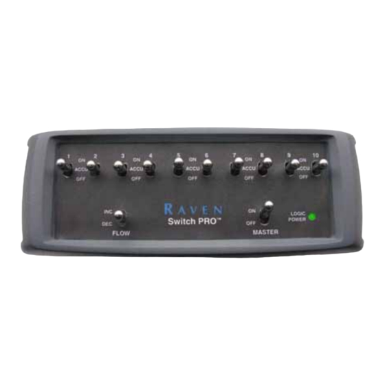
Control console
Hide thumbs
Also See for Switch Pro:
- User manual (32 pages) ,
- Quick start manual (2 pages) ,
- Quick start manual (2 pages)
Table of Contents
Advertisement
Quick Links
Download this manual
See also:
User Manual
Advertisement
Table of Contents

Related Manuals for Raven Switch Pro


Summary of Contents for Raven Switch Pro
- Page 1 Raven Switch Pro™ Installation & Reference Manual Manual No. 016-0171-219 Rev E 07/17 E29805 Copyright 2017...
- Page 2 GPS, GNSS, SBAS, etc.). Therefore, Raven Industries cannot guarantee the accuracy, integrity, continuity, or availability of these services and cannot guarantee the ability to use Raven systems, or products used as components of systems, which rely upon the reception of these signals or availability of these services.
-
Page 3: Table Of Contents
..................3 Master Switch ........................4 3-Way Selectable Section Switches ..................4 Using AccuBoom Override ......................4 Appendix A Switch Pro Combo Cable ............5 Combo Cable Installation ......................5 Speed Input Terminal Configuration ..................5 Power Connections ......................5 Switch Pro Combo Cable Connections ................ - Page 4 Table of Contents Coverage Map Issues ......................19 CAN Troubleshooting ......................19 Raven Switch Pro™ Installation & Reference Manual...
-
Page 5: Chapter 2 Installation
Off position to allow Switch Pro to operate properly. If a Remote Master Switch will be used with the Switch Pro, both master switches must be in the Off position to turn off booms. Toggling either the Switch Pro master or the remote master will enable boom sections. -
Page 6: Mounting Tips
Keep the console clear of moving elements within the machine’s cab. • All cables connected to the Switch Pro switch box should be routed to avoid kinks in the cables and tripping hazards. If the Switch Pro will be mounted together with an Envizio Pro or Viper Pro field computer: •... - Page 7 2. Use the supplied hardware to fasten the mounting bracket and RAM mounting arm to the Envizio Pro field computer. 3. Use the supplied hardware to mount the Switch Pro switch box to the lower flange of the mounting bracket. Manual No. 016-0171-219 Rev E...
-
Page 8: Cables And Wiring
CABLES AND WIRING Wiring power to the Envizio Pro or Viper Pro field computer, Switch Pro switch box, and the CAN nodes is especially important for proper operation of the system. Many issues can be corrected by diagnosing and fixing problems related to improper wiring of the power and ground. -
Page 9: Chapter 1 Introduction
These cables will be connected to the Switch Pro switch box which then allows the Raven Envizio Pro or Viper Pro field computer to replace the SCS console as the product controller. -
Page 10: Switch Pro Kit Contents
Viper Pro Mounting Bracket Kit 115-0171-181 Optional RAM Mount Components Required for Remote Mounting Switch Pro switch box: RAM Mount Socket Arm 103-0001-014 RAM Ball Mount Base, Circular 103-0001-015 RAM Ball Mount Base, Diamond Shaped 103-0001-016 Raven Switch Pro™ Installation & Reference Manual... -
Page 11: Chapter 2 Using The Switch Pro System
CANbus system. NOTE: To ensure proper operation of the Switch Pro system, make sure the field computer has the latest version of software. Switch Pro requires Viper Pro version 2.52 or higher or Envizio Pro version 1.00C or higher. -
Page 12: Master Switch
MASTER SWITCH The Switch Pro master switch toggles all section switches on or off. When the master switch is in the ON position, each section will function according to the corresponding section switch (see below for details). Toggle the master switch to OFF to turn off all boom sections manually. -
Page 13: Appendix A Switch Pro Combo Cable
The combo cable can be used in place of the Envizio Pro or Viper Pro main and auxiliary interface cables (P/N 115- 0171-745 and 746), CAN tee cables (P/N 115-0171-326 and 368) and Switch Pro console cable (P/N 115-0171-803). NOTE: Be sure to follow the instructions in the Preparation section on page 1 and Best Wiring Practices section on page 4 when installing the Switch Pro combo cable. -
Page 14: Switch Pro Combo Cable Connections
For kits with combo cable (P/N 115-0171-821) to SCS 4400 cabling, connect the 37-pin connectors on the existing console cable and combo cable. 4. Insert the Switch Pro logic power connector to the power port on the back of the Switch Pro unit. Switch Pro Cable Port Logic Power Port 5. -
Page 15: Appendix B System Diagrams
A P P E N D I X B The following system diagrams may be helpful during installation or to troubleshoot the Switch Pro system. Be sure to locate the appropriate system diagram for the Switch Pro system currently installed. - Page 16 PPENDIX FIGURE 1. Envizio Pro with Switch Pro for SCS 440/450 Cabled Systems Raven Switch Pro™ Installation & Reference Manual...
- Page 17 FIGURE 2. Viper Pro with Switch Pro for SCS 440/450 Cabled Systems...
-
Page 18: Switch Pro For Scs 4400 Cabled Systems
PPENDIX SWITCH PRO FOR SCS 4400 CABLED SYSTEMS Refer to the following diagrams in reference to Switch Pro systems replacing an SCS 4400 console with the 117- 0171-168 kits. FIGURE 3. Envizio Pro with Switch Pro for SCS 4400 Cabled Systems... - Page 19 FIGURE 4. Viper Pro with Switch Pro for SCS 4400 Cabled Systems...
-
Page 20: Switch Pro Combo Cable To Scs 440/450 Systems
Refer to the following diagram when using the combo cable (P/N 115-0171-820) for SCS 440/450 Systems (Kits 117- 0171-169 or 170). FIGURE 5. Envizio Pro with Switch Pro Combo Cable for SCS 440/450 Cabled Systems Raven Switch Pro™ Installation & Reference Manual... - Page 21 FIGURE 6. Viper Pro with Switch Pro Combo Cable for SCS 440/450 Cabled Systems...
-
Page 22: Switch Pro Combo Cable To Scs 4400 Systems
Refer to the following diagram when using the combo cable (P/N 115-0171-821) for SCS 4400 Systems (Kits 117- 0171-171 or 172). FIGURE 7. Envizio Pro with Switch Pro Combo Cable for SCS 4400 Cabled Systems Raven Switch Pro™ Installation & Reference Manual... - Page 23 FIGURE 8. Viper Pro with Switch Pro Combo Cable for SCS 4400 Cabled Systems...
- Page 24 PPENDIX Raven Switch Pro™ Installation & Reference Manual...
-
Page 25: Appendix C Troubleshooting
Switch Pro. Switch Pro wired Connect the Switch Pro switch box to the auxiliary power output on Vehicle battery directly to the the interface or combo cable to switch power with the field discharges overnight battery. -
Page 26: Setup Issues
Remote section Toggle all remote section switches to the OFF position. Remote painting but boom switches left in the switches will override Switch Pro section switches and AccuBoom, sections are on ON position automatic section control, features. Raven Switch Pro™ Installation & Reference Manual... -
Page 27: Coverage Map Issues
Possible Cause Solution Check Switch Pro auxiliary power connection. Switch Pro is not Check the CANbus connection to the Switch Pro and re-initialize the properly connected console to read the Switch Pro nodes. Ensure console is powered on. No Power to Switch Check console power and ground lead connections. - Page 28 PPENDIX Raven Switch Pro™ Installation & Reference Manual...
- Page 29 Coverage Map Issues 19 Connecting the Switch PRO General Issues 17 Job Issues 18 Setup Issues 18 Existing SCS Console Calibration Values Using the Switch PRO System Features Flow Switch Increase/Decrease Flow Switch Installation Cables and Wiring vi Combo Cable 5...
- Page 30 Index Raven Switch Pro™ Installation & Reference Manual...
-
Page 31: Limited Warranty
Bring the defective part and proof of purchase to your Raven dealer. If the dealer approves the warranty claim, the dealer will process the claim and send it to Raven Industries for final approval. The freight cost to Raven Industries will be the customer’s responsibility. - Page 32 Bring the defective part and proof of purchase to your Raven dealer. If the dealer approves the warranty claim, the dealer will process the claim and send it to Raven Industries for final approval. The freight cost to Raven Industries will be the customer’s responsibility.
Need help?
Do you have a question about the Switch Pro and is the answer not in the manual?
Questions and answers