
Related Manuals for Raven SCS660M


Summary of Contents for Raven SCS660M
- Page 1 Installation & Service Manual SCS 660 & 660M Serial Interface for Granular Applications...
- Page 2 Raven Industries shall not be held responsible or liable for the effects of atmospheric conditions and sunspot activity on the performance of our products. Raven Industries cannot guarantee the accuracy, integrity, continuity, or availability of the GPS signal from the U.S.
-
Page 3: Table Of Contents
Chapter 4 Installation................13 Sensor Installation ........................13 Raven Radar Speed Sensor ....................13 Wheel Drive Speed Sensor ....................14 Rim Drilling for Four and Eight Hole Wheel Stud Patterns - Optional ......14 Rim Drilling for Six Hole Wheel Stud Patterns - Optional ..........15 Mounting the Wheel Drive Speed Sensor .............. - Page 4 Data Entry .......................... 29 Initial Console Programming ..................... 29 Refining the Speed Cal Value - Raven Radar Only ............30 Refining the Speed Cal Value - Phoenix 10 Speed Sensors Only ......... 31 Refining the Spreader Constant Value ................31 Programming for New Leader Mark IV Interface ...............
- Page 5 Table of Contents Testing Flow Meter/Encoder Cables .................. 43 Speed Sensor Cables ......................44 Testing Speed Sensor Extension Cables ................44 Troubleshooting ........................45 Console Issues ........................45 Rate Control Issues ......................46 Chapter 8 Replacement Parts ............... 49 Manual No. 016-0159-845...
- Page 6 Table of Contents SCS 660 & 660M Serial Interface for Granular Applications Installation & Service Manual...
-
Page 7: Important Safety Information
• Follow all safety information presented within this manual. • If you require assistance with any portion of the installation or service of your Raven equipment, contact your local Raven dealer for support. • Follow all safety labels affixed to the system components. Be sure to keep safety labels in good condition and replace any missing or damaged labels. -
Page 8: Hydraulic Safety
CAUTION Hydraulic Safety • Raven Industries recommends that appropriate protective equipment be worn at all times when working on the hydraulic system. • Never attempt to open or work on a hydraulic system with the equipment running. Care should always be taken when opening a system that has been previously pressurized. -
Page 9: Chapter 2 Introduction
Congratulations on your purchase of the Raven SCS (Sprayer Control System) 660 Serial Interface! The Raven SCS 660 is designed to provide uniformity of granular applications, regardless of the vehicle’s speed. Utilizing a computer-based console, a speed sensor, an encoder, and a hydraulic control valve, the SCS 660 also functions as an area monitor, speed monitor, and volume totalizer. -
Page 10: Unit Definitions And Conversions
Chapter 2 Unit Definitions and Conversions Unit of Measure Definitions Abbreviation Definition Abbreviation Definition Pounds per Minute Meter kg/min Kilograms per Minute Miles per Hour Pounds per Acre Kilometers kg/ha Kilograms per Hectare km/h Kilometers per Hour Pounds per 1,000 Square Feet Volume per Acre Millimeters Volume per Hectare... -
Page 11: Calculating Machine's Calibration Values
Calculate the Speed Cal Value Raven Radar Only The initial Speed Cal value for Raven radar is 598 [152]. After the initial console programming has been performed, this value may be adjusted to optimize the system’s performance. Phoenix 10 Speed Sensors Only The initial Speed Cal value for Phoenix 10 speed sensors is 785 [200]. -
Page 12: Calculate The Spreader Constant Value
Chapter 2 Measure the distance (in inches/cm) from the ground starting mark to the stopping mark. Round off fractions of an inch/cm. Write down this number as it will be used as the Speed Cal value when programming the console. Note: Large tires and very low speed applications may require additional magnets to ensure accurate speed readings. -
Page 13: Catch Test Calculation
Introduction D x GH x GW Cubic Feet of Discharge per 1 Sensor Revolution 1728 13 x 7 x 15 .790 cubic feet of discharge per 1 sensor revolution 1728 [33] x [7] x [15] 22,572 cubic cm of discharge per 1 sensor revolution Note: When cubic inches are being converted to cubic feet, it is necessary to divide the product by 1728. -
Page 14: New Leader Mark Iv Interface Spreader Constant Values
Chapter 2 For Example: METER CAL TOTAL VOLUME Actual Volume (Weight of Collected Material) Product Density 50 lbs./cu ft 200 x 200 1562 (Spreader Constant Value) Write down the Spreader Constant and product density values for future reference when programming the console. -
Page 15: Calculate The Meter Cal Value
Introduction Calculate the Meter Cal Value No calculation of the Meter Cal value is necessary. Enter the product density in pounds/ft [gram/liter] as the Meter Cal value. Note: The Meter Cal value will vary according to the product being applied. To increase the system accuracy when applying at low rates, use the decimal shift feature explained in the Decimal Shift Feature section on page 39. -
Page 16: Calculate The Rate Cal Value
Chapter 2 Digit Description Range Range Definition Controls the time of the first correction pulse 1 = Short Pulse Valve Backlash after a change in correction direction is 1 - 9 9 = Long Pulse detected (INC to DEC, or DEC to INC) Controls the response time of the control valve Refer to Refer to specific... -
Page 17: Calibration Card
C alibration Card CHAPTER C h a p t e r 3 Introduction Located on the next page is a card that may be used to record the machine’s calibration values. Write the calibration numbers in pencil so that they may be revised if necessary. Cut on the dotted line, fold, and insert the card into the plastic envelope provided for your convenience. - Page 18 Chapter 3 SCS 660 & 660M Serial Interface for Granular Applications Installation & Service Manual...
-
Page 19: Installation
C h a p t e r 4 Sensor Installation Raven Radar Speed Sensor Note: Raven Industries recommends the installation of a large, heavy mounting bracket (P/N 107-0159- 693) on the machine’s frame for mounting the radar speed sensor. Radar Mounting Locations FIGURE 1. -
Page 20: Wheel Drive Speed Sensor
Chapter 4 Use a level to verify that the selected mounting bracket location is parallel to the ground. Bolt the mounting bracket to the machine. Radar Mounting FIGURE 2. Bolt the radar to the mounted bracket using the supplied mounting hardware. Connect the radar power cable (P/N 115-0159-539) to the radar. -
Page 21: Rim Drilling For Six Hole Wheel Stud Patterns - Optional
Installation Rim Drilling for Six Hole Wheel Stud Patterns - Optional This section is required only on wheels that do not have pre-punched mounting holes. If your machine has the pre-punched mounting holes, proceed to the Mounting the Wheel Drive Speed Sensor section. Six Hole Stud Pattern FIGURE 4. -
Page 22: Phoenix 10 Gps Speed Sensor
Chapter 4 Switch Assembly Installed FIGURE 6. Note: The switch assembly does not need to pivot with the wheel. Loosely mount the switch assembly to the wheel axle with the supplied hardware, positioning it so that as the wheel rotates, the magnets pass across the center of the switch assembly. •... -
Page 23: Fan Sensor
Installation Fan Sensor Fan Sensor Assembly FIGURE 8. Attach the fan RPM sensor to the fan sensor bracket using a stainless steel bolt, lock washer, and nut. Mount the fan sensor assembly on the fan sensor mounting tab using a stainless steel bolt, lock washer, and nut. -
Page 24: Bin Level Sensor
Chapter 4 Bin Level Sensor The mounting location of the bin level sensor is influenced by the bin construction. Determine the type of bin being used and mount the sensor accordingly. Bin Level Sensor Mounting Locations FIGURE 10. Mounted Bin Level Sensor FIGURE 11. -
Page 25: Encoder Installation
Installation Encoder Installation Mounting the Encoder Encoder Installation Diagram FIGURE 12. Install a mounting bracket (not supplied) to a secure mounting surface on the machine. Apply grease to the encoder shaft, the conveyor shaft, and the encoder coupler. Install the coupler on the end of the encoder. Mount the encoder and coupler on the output shaft of the conveyor. -
Page 26: Control Valve Installation
Chapter 4 Control Valve Installation Install the Control Valve Control Valve Installation Diagram FIGURE 13. Spinner System Open Hydraulic System (Fixed Displacement Pump) Closed Hydraulic System (Variable Displacement Pump) Pneumatic System Closed Hydraulic System (Variable Displacement Pump) Open Hydraulic System (Fixed Displacement Pump) Install the control valve with the motor in the upright position, in the location appropriate for the machine’s configuration. -
Page 27: Console And Cabling Installation
Connect the female end of the console control cable into the back of the console. If using the Raven radar speed sensor: • Connect the red wire on the radar power cable to the orange cable wire on the console control cable. - Page 28 Chapter 4 SCS 660 Console Cabling Diagram FIGURE 14. SCS 660 & 660M Serial Interface for Granular Applications Installation & Service Manual...
- Page 29 Installation SCS 660M Console Cabling Diagram FIGURE 15. Manual No. 016-0159-845...
-
Page 30: Battery Connections
Chapter 4 Battery Connections Note: If the system will not be used for an extended period of time (for example, two weeks), be sure to disconnect the SCS 660 battery wires. If the wires are not disconnected and the SCS 660 is only turned OFF, the system will continue to draw 0.25 milliamperes of current to maintain information stored in the console computer, draining the battery. -
Page 31: Console Identification
Console Identification There may be situations that arise during which it may be necessary to contact Raven Industries with questions about the SCS 660 system. The SCS 660 console has an identification label affixed that contains information useful to the Raven customer support team to identify potential issues with the console or system. Please refer to this information on the console when calling to request assistance. -
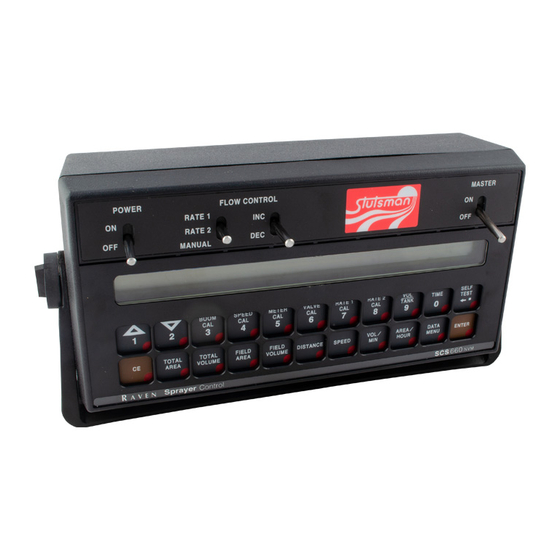
Page 32: Console Features
Chapter 5 Console Features SCS 660 Serial Console FIGURE 2. SCS 660 & 660M Serial Interface for Granular Applications Installation & Service Manual... -
Page 33: Chapter 5 Console Programming And Calibration
Console Programming and Calibration SCS 660M Serial Console FIGURE 3. Manual No. 016-0159-845... -
Page 34: Button Definitions
Chapter 5 Button Definitions Calibration Buttons The calibration buttons are used to enter data into the console when calibrating the system. Refer to the table below for the button names and functions. Button Name Function BOOM CAL Length of the boom. Select the boom number by using the up/down arrow keys. SPEED CAL Determined by speed sensor. -
Page 35: Console Programming
Console Programming and Calibration Console Programming Data Entry Note: Data must be entered for all booms and for each of the variables. If a boom is not in use, enter 0 as the value for that boom. Press the number key that corresponds with the variable to be changed: •... -
Page 36: Refining The Speed Cal Value - Raven Radar Only
Refining the Speed Cal Value - Raven Radar Only The initial Speed Cal value when using Raven radar is 598 [152]. However, after initial console programming, it may be necessary to refine this number to improve the system’s performance. Complete the following steps to refine the speed cal value: Set the boom POWER switches to ON. -
Page 37: Refining The Speed Cal Value - Phoenix 10 Speed Sensors Only
Console Programming and Calibration [152] x [1000] 155 [metric] [980] Important: The new Speed Cal value must be rounded to the nearest whole number. Enter the adjusted Speed Cal value. Recheck the new Speed Cal value by repeating the steps above. Refining the Speed Cal Value - Phoenix 10 Speed Sensors Only The initial Speed Cal value when using the Phoenix 10 speed sensor is 785 [200]. -
Page 38: Programming For New Leader Mark Iv Interface
Chapter 5 Press TOTAL VOLUME and enter 0 as the value. Switch the RATE 1/RATE 2/MAN switch to the MAN position. Unload a portion of the product by turning the boom switch to ON. Determine the actual weight unloaded by re-weighing the vehicle and subtracting the vehicle’s current weight from the beginning weight. -
Page 39: Programming Additional System Data
Console Programming and Calibration Changing Initial Console Programming Occasionally it is necessary to make changes to the console programming after the initial programming is complete. To make changes to the initial setup: Press SELF TEST and hold it for 30 seconds. The console’s display will flash the current program setting. Press ENTER to advance to the setting that needs to be changed. -
Page 40: System Features
Menu Option Function Sends data through the serial port to the attached printer (optional - not supplied by Raven) to Print Field Begin and Print Field End pages. Pressing CE will toggle between the two pages. PRINT FIELD BEGIN Press ENTER to print the Print Field Begin. The display will now show PRINT FIELD END. -
Page 41: Data Logger On/Off
Note: When connecting to a Raven field computer, it is not necessary to turn the DATA LOGGER on. Some options within the Data Menu are unavailable when certain other features are active. The console data printout is not available when the data logger is on. -
Page 42: Self Test Feature
SCS 660 Console to Remote Computer Data Strings All request strings begin with $R, indicating a Raven communication string. In the example below, the 126 value indicates the last three digits of the programmed chip part number in the console, and C is the software revision letter of the console. -
Page 43: Volume/Min Rate Fault
Console Programming and Calibration Enter the desired simulated speed value. Verify the vehicle’s speed by pressing the SPEED button. Volume/Min Rate Fault The low limit value is the minimum volume per minute allowed before the valve stops closing, an alarm sounds, and the SCS 660 console displays the message “LOW LIMIT.”... -
Page 44: Control Valve Delay And Valve Advance
Chapter 5 Control Valve Delay and Valve Advance Note: PGM 126 requires Rev D or greater to support the Valve Advance feature. The Control Valve Delay feature allows the user to set a delay between the time the booms are turned on and when the console begins to control the flow rate. -
Page 45: Entering Data In The Data Lock Mode
Console Programming and Calibration Enter the new 4-digit code within 15 seconds, or enter 0 to disable the Data-Lock feature. Press ENTER. Entering Data in the Data Lock Mode Press the button of the variable to be edited. Press ENTER. A message prompting for the data-lock code will appear. Enter the data-lock code. -
Page 46: Shift The Decimal Place
Chapter 5 Shift the Decimal Place Press the METER CAL button. Press the SELF TEST button. Enter the flow meter calibration value stamped on the identification tag. Press ENTER. Unshift the Decimal Place Press the METER CAL button. Enter the flow meter calibration value stamped on the identification tag. Press ENTER. -
Page 47: Initial System Setup And Testing
I nitial System Setup CHAPTER C h a p t e r 6 and Testing Initial System Setup After all components of the system have been installed and the console has been programmed, the SCS 660 is ready to be set up. Complete the following steps to set up the SCS 660 system. Completely empty the bin of product. - Page 48 Chapter 6 performing correctly, refer to Chapter 7, Preventative Maintenance and Troubleshooting for possible causes and corrective action. At the end of each row, switch the boom switches to OFF to shut off the application. This also turns off the area totalizer.
-
Page 49: Preventative Maintenance And Troubleshooting
P reventative CHAPTER C h a p t e r 7 Maintenance and Troubleshooting General Preventative Maintenance Preventative maintenance is extremely important to ensure the long life of your machine and the SCS 660 system. The following preventative maintenance measures should be taken on a regular basis: Remove the console from the cab when not in use for extended periods of time. -
Page 50: Speed Sensor Cables
Chapter 7 Repeat the ground-signal short test. • If the TOTAL VOLUME increases, replace the defective cable and repeat the ground-signal short test. • If the TOTAL VOLUME does not increase, replace the flow sensor. Perform voltage checks as illustrated in the figure above. Important: Re-enter the original METER CAL and SPREADER CONSTANT figures after testing is complete. -
Page 51: Troubleshooting
Preventative Maintenance and Troubleshooting Troubleshooting Console Issues Issue Corrective Action Check the fuse on the back of the console. Check the battery connections. The console is on, but there are no Check the operation of the Power ON/OFF switch. lights lit up on the console. Return the console to the dealer to have the processor board assembly replaced. -
Page 52: Rate Control Issues
Chapter 7 Issue Corrective Action Check the speed sensor. Run a speed check on a hard surface road. If the speed is accurate, move the speed sensor to a different wheel and perform a recheck. Check the magnets. Remove one red magnet and one black magnet on the wheel. - Page 53 Preventative Maintenance and Troubleshooting Issue Corrective Action Check the cabling to the motorized control valve for breaks in the line. Verify the cable connections are clean. Verify that there is voltage to the valve connector. Turn the Master switch ON. Cannot vary the RATE in automatic or manual operation.
- Page 54 Chapter 7 SCS 660 & 660M Serial Interface for Granular Applications Installation & Service Manual...
-
Page 55: Replacement Parts
R eplacement Parts CHAPTER C h a p t e r 8 SCS 660 & 660M Serial Interface for Granular Applications Installation & Service Manual... - Page 56 Chapter 8 SCS 660 & 660M Serial Interface for Granular Applications Installation & Service Manual...
- Page 57 Installing the Control Valve 20 Encoder 19 Mounting the Encoder 19 Sensors 13 Phoenix 10 GPS Speed Sensor 16 Raven Radar Speed Sensor 13 Wheel Drive Speed Sensors 14 Introduction Calculating Machine Calibration Values 5 Boom Cal Value 5 Meter Cal 9...
- Page 58 Index SCS 660 & 660M Serial Interface for Granular Applications Installation & Service Manual...
-
Page 59: Limited Warranty
How Can I Get Service? Bring the defective part and proof of purchase to your Raven Dealer. If your Dealer agrees with the warranty claim, the Dealer will send the part and proof of purchase to their distributor or to Raven Industries for final approval. - Page 60 P.O. Box 5107 Fax: 605-331-0426 Sioux Falls, SD 57117-5107 www.ravenprecision.com atdinfo@ravenind.com Notice: This document and the information provided are the property of Raven Industries, Inc. and may only be used as authorized by Raven Industries, Inc. All rights reserved under copyright laws.
Need help?
Do you have a question about the SCS660M and is the answer not in the manual?
Questions and answers