Table of Contents
Advertisement
Quick Links
User Manual
VE-120
Read this guide thoroughly and follow the installation and operation
procedures carefully in order to prevent any damage to the units and/or
any devices that connect to them.
This package contains:
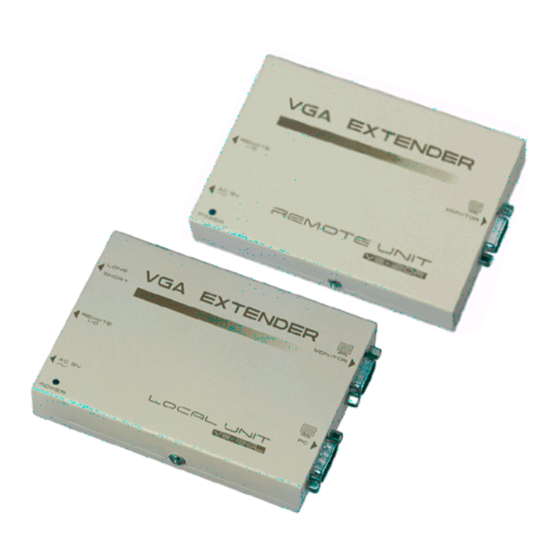
M 1 VE-120L Video Extender (Local Unit)
M 1 VE-120R Video Extender (Remote Unit)
M 1 VGA Cable
M 2 Power Adapters
M 1 User Manual
If anything is damaged or missing, contact your dealer.
®
© Copyright 1999-2003 ATEN
International Co., Ltd.
Manual Part No. PAPE - 1141-200
Printed in Taiwan 10/2003
Advertisement
Table of Contents

Related Manuals for ATEN VE-120


Summary of Contents for ATEN VE-120
-
Page 1: User Manual
M 1 VE-120R Video Extender (Remote Unit) M 1 VGA Cable M 2 Power Adapters M 1 User Manual If anything is damaged or missing, contact your dealer. ® © Copyright 1999-2003 ATEN International Co., Ltd. Manual Part No. PAPE - 1141-200 Printed in Taiwan 10/2003... - Page 2 NOTE: This equipment has been tested and found to comply with the limits for a Class B digital device pursuant to Subpart J of Part 15 of FCC Rules. These limits are designed to provide reasonable protection against harmful interference in a residential installation.
- Page 3 Overview The VE-120 Video Extender System allows you to extend the distance between the computer system unit and the display monitor by up to 130 meters (430 feet). It accomplishes this by means of a local transmitting unit (VE-120L), and remote receiving unit (VE-120R), connected by Category 5 twisted pair Ethernet cable.
-
Page 4: System Requirements
Features M Uses economical, reliable, Category 5 Ethernet cable to connect the local and remote units M Easy installation - connecting cables is all it takes M High resolution video - up to 1600 x 1200 @ 100m M Supports VGA, SVGA, and Multisync Monitors M Long distance transmission - up to 130m (430’) System Requirements M A PC compatible computer with a VGA output port... - Page 5 Components The Local Unit (VE-120L) 1. Range Switch Slide the switch to the Long position if the Remote Unit is located a long distance away; slide the switch to the Short position if the Remote Unit is located a short distance away. 2.
- Page 6 The Remote Unit (VE-120R) 1. Remote I/O The Category 5 twisted pair cable that connects to the Remote Unit plugs in here. 2. AC 9V Power Jack The AC 9V power adapter’s cable plugs in here. 3. Power LED Lights to indicate that the unit is receiving power. 4.
-
Page 7: Installation
To prevent damage to your installation, make sure that all devices are properly grounded. Setting up the Video Extender System is simply a matter of plugging in the cables. Refer to the diagram below as you perform the following installation procedures. The numbers in the diagram correspond to the numbers of the steps: 1. - Page 8 6. Plug the remote monitor’s VGA cable into the Remote Unit’s Monitor port. 7. Plug the second power adapter (supplied with this package) into an AC source; plug the adapter’s power cable into the Remote Unit’s Power Jack. 8. Power On the computer and monitors. - 6 -...
-
Page 9: Tp Pin Assignments
Appendix Cable Length Table Resolution 640 x 480 800 x 600 1024 x 768 1280 x 1024 1600 x 1200 TP Pin Assignments Assignment V OUT G /V OUT G V OUT B V OUT R /V OUT R /V OUT B Distance (meters) @ 60Hz @ 75Hz... -
Page 10: Tp Wiring Diagram
TP Wiring Diagram Troubleshooting Symptom No Video Make sure that all cables are securely plugged into their sockets. PAIR 3 PAIR 2 PAIR 1 PAIR 4 1 2 3 4 5 6 Bl W-Bl G W-Br Br JACK POSITIONS T568B AT&T 258A Action - 8 -... -
Page 11: Specifications
Specifications Function Connectors Input Output LEDs Video Resolution Signal Type Cable Type Length Power Consumption Housing Weight Dimensions (L x W x H) VE-120L 15 pin HDB male 15 pin HDB female RJ-45 Socket 1 Power 640 x 480 @ 130m - 1600 x 1200 @ 100m VGA, SVGA, Multisync Category 5 STP 130m (430’) - Page 12 Limited Warranty IN NO EVENT SHALL THE DIRECT VENDOR’S LIABILITY EXCEED THE PRICE PAID FOR THE PRODUCT FROM DIRECT, INDIRECT, SPECIAL, INCIDENTAL, OR CONSEQUENTIAL DAMAGES RESULTING FROM THE USE OF THE PRODUCT, DISK, OR ITS DOCUMENTATION. The direct vendor makes no warranty or representation, expressed, implied, or statutory with respect to the contents or use of this documentation, and especially disclaims its quality, performance, merchantability, or fitness for any particular...
- Page 13 Notes: - 11 -...
- Page 14 Notes: - 12 -...
- Page 15 Notes: - 13 -...
- Page 16 Notes: - 14 -...
Need help?
Do you have a question about the VE-120 and is the answer not in the manual?
Questions and answers