
Subscribe to Our Youtube Channel
Related Manuals for ATEN VanCryst VE8900


Summary of Contents for ATEN VanCryst VE8900
- Page 1 ATEN VanCryst™ VE8900 / VE8950 / VE8952 HDMI over IP Video Extender Series User Manual...
-
Page 2: Compliance Statements
VE8900 / VE8950 / VE8952 User Manual Compliance Statements FEDERAL COMMUNICATIONS COMMISSION INTERFERENCE STATEMENT This equipment has been tested and found to comply with the limits for a Class A digital device, pursuant to Part 15 of the FCC Rules. These limits are designed to provide reasonable protection against harmful interference when the equipment is operated in a commercial environment. - Page 3 VE8900 / VE8950 / VE8952 User Manual HDMI Trademark Statement The terms HDMI, HDMI High-Definition Multimedia Interface, and the HDMI Logo are trademarks or registered trademarks of HDMI Licensing Administrator, Inc. RoHS This product is RoHS compliant.
-
Page 4: User Information
Japan 81-3-5615-5811 Korea 82-2-467-6789 North America 1-888-999-ATEN ext 4988 1-949-428-1111 User Notice All information, documentation, and specifications contained in this manual are subject to change without prior notification by the manufacturer. The manufacturer makes no representations or warranties, either expressed or implied, with respect to the contents hereof and specifically disclaims any warranties as to merchantability or fitness for any particular purpose. -
Page 5: Product Information
For information about all ATEN products and how they can help you connect without limits, visit ATEN on the Web or contact an ATEN Authorized Reseller. Visit ATEN on the Web for a list of locations and telephone numbers: International http://www.aten.com... -
Page 6: Package Contents
VE8900 / VE8950 / VE8952 User Manual Package Contents Check to make sure that all of the components are in working order. If you encounter any problem, please contact your dealer. VE8900T 1 VE8900 HDMI over IP Transmitter 1 RS-232 terminal block 1 5V power adapter 4 foot pads 1 user instructions... - Page 7 VE8900 / VE8950 / VE8952 User Manual VE8950R 1 VE8950 4K HDMI over IP Receiver 1 RS-232 terminal block 1 5V power adapter 4 foot pads 1 user instructions VE8952R 1 VE8952 4K HDMI over IP Receiver with PoE 1 RS-232 terminal block 1 5V power adapter 4 foot pads 1 user instructions...
-
Page 8: Table Of Contents
VE8900 / VE8950 / VE8952 User Manual Contents Compliance Statements ........ii User Information . - Page 9 VE8900 / VE8950 / VE8952 User Manual Creating a Video Wall Layout ....... 40 Editing a Video Wall Layout .
- Page 10 VE8900 / VE8950 / VE8952 User Manual Disabling a Video Output ........77 Enabling / Disabling the OSD Display of a Receiver .
-
Page 11: About This Manual
About This Manual This User Manual is provided to help you get the most from your VE8900 / VE8950 / VE8952 device and the ATEN VE Manager. It covers all aspects of installation, configuration, and operation. An overview of the information found in the manual is provided below. -
Page 12: Conventions
VE8900 / VE8950 / VE8952 User Manual Conventions This manual uses the following conventions: Monospaced Indicates text that you should key in. Indicates keys you should press. For example, [Enter] means to press the Enter key. If keys need to be chorded, they appear together in the same bracket with a plus sign between them: [Ctrl+Alt]. -
Page 13: Introduction And Getting Started
1080p (VE8900) / 4K AV (VE8950 / VE8952) signals with low latency over long distance via a standard Gigabit Ethernet switch. ATEN’s Video over IP solution is desiged to address the challenges that system integrators encounter when implementing AV over IP solutions and provides... -
Page 14: Features And Benefits
Delivers visually lossless high-quality video up to 1080p @ 60 Hz (VE8900) / 4K @ 30 Hz 4:4:4 (VE8950 / VE8952) Ensures stunning quality video using ATEN advanced video lossless compression technology EDID Expert™ selects the optimum EDID settings for smooth power-up, high-quality display and the best video resolution across different screens ... - Page 15 Only VE8952 supports PoE and can be installed in combination with PoE Ethernet switches to reduce power cabling and additional power outlets. For more information about choosing the Ethernet switch or bandwidth requirements; refer to the ATEN HDMI over IP Video Extender System Implementation Guide.
- Page 16 VE8900 / VE8950 / VE8952 User Manual Spontaneous Scheduling Management Offers an user-friendly scheduling management function for users to pre- plan the display schedule Provides robust and intuitive scheduling management options to help users to manage all events in the calendar to as detailed as to setting events to minute intervals ...
- Page 17 Note: Depending on your network architecture, we recommend daisy chaining up to 30 units. Please contact ATEN representatives for more details. For Daisy Chain installation setup for VE8952 units, only the first level of VE8952 supports PoE powering function. All the other VE8952 units installed on the second level or above will need power adapter and PoE does not work.
- Page 18 Easily switches layout profiles, preview and drag-and-drop video sources via the intuitive web GUI Note: If you experience issues related to your network architecture, please contact ATEN representatives for support. Embedded / De-embedded Audio Support For VE8900T / VE8950T / VE8952T – separate audio signal can be embedded into the HDMI stream ...
-
Page 19: Getting Started Tasks
VE8900 / VE8950 / VE8952 devices. 1. Decide your network architecture and configuration. For more information, see the ATEN HDMI over IP Video Extender System Implementation Guide. 2. Mount your VE8900 / VE8950 / VE8952 devices on walls or racks. For more information, see Mounting the VE8900 / VE8950 / VE8952 Device, page 14. - Page 20 VE8900 / VE8950 / VE8952 User Manual This Page Intentionally Left Blank...
-
Page 21: Hardware Setup
Chapter 2 Hardware Setup Before you proceed to hardware setup: 1. Please review the safety information regarding the placement of this device in Safety Instructions, page 101. 2. Do not power on the VE8900 / VE8950 / VE8952 device until all the necessary hardware is connected. -
Page 22: Ve8900T / Ve8950T / Ve8952T Rear View
VE8900 / VE8950 / VE8952 User Manual VE8900T / VE8950T / VE8952T Rear View Component Function LAN port with Connects the unit to LAN with a network cable. Note: Only VE8952 supports PoE function, and VE8900 / VE8950 does not. power jack Connects to the DC power adapter to provide power to the unit. - Page 23 Chapter 2. Hardware Setup VE8900R / VE8950R / VE8952R Rear View No. Component Function LAN 1 port Connects the unit to LAN with a network cable. with PoE Note: Only VE8952 supports PoE function, and VE8900 / VE8950 does not. LAN 2 port Connects to another VE8900R / VE8950R with a network cable in a daisy-chain setup.
-
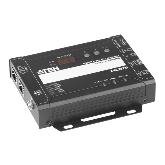
Page 24: Ve8900T / Ve8950T / Ve8952T Top View
VE8900 / VE8950 / VE8952 User Manual VE8900T / VE8950T / VE8952T Top View No. Component Function ID display An ID display that identifies its ID number. panel prev (+) / next Assign ID numbers on VE8900 / VE8950 devices. (-) buttons ... -
Page 25: Ve8900R / Ve8950R / Ve8952R Top View
Chapter 2. Hardware Setup VE8900R / VE8950R / VE8952R Top View No. Component Function Tx / Rx LEDs Lights to indicate whether the displayed ID number is of Tx or ID display An ID display that identifies its ID number or the transmitter’s ID panel number when the panel control is switched to Tx. -
Page 26: Mounting The Ve8900 / Ve8950 / Ve8952 Device
Secure or hang the VE8900 / VE8950 / VE8952 device to the wall using the built-in brackets. Rack Mount Use the VE-RMK1U Rack Mount Kit to rack-mount the VE8900 / VE8950 / VE8952. For more information about this accessory, go to www.aten.com/ products... -
Page 27: Connecting Ve8900 / Ve8950
Note: For details on LED indicators to help you identify statuses of connection or signal transmission, see Status LEDs, page 21. For a list of compatible ATEN products, visit the VE8900 / VE8950 product web page at www.aten.com... - Page 28 VE8900 / VE8950 / VE8952 User Manual 1. Connect the HDMI In port on the VE8900T / VE8950T device to the HDMI output port on your video source device using an HDMI cable. 2. Connect the HDMI Out port on the VE8900R / VE8950R device to the HDMI input port on your display device using an HDMI cable.
- Page 29 Chapter 2. Hardware Setup Note: 1. The IR, RS-232, and USB signal transmissions are disabled by default. To enable the functions, go to System Settings > Receiver > IR/RS232 or USB in VE Manager and select the signal source. 2. Each VE8900 / VE8950 transmitter can be controlled by a total of 4 USB touch screens installed to VE8900 / VE8950 receivers.
-
Page 30: Connecting Ve8952
Note: For details on LED indicators to help you identify statuses of connection or signal transmission, see Status LEDs, page 21. For a list of compatible ATEN products, visit the VE8952 product web page at www.aten.com Audio Speaker... - Page 31 Chapter 2. Hardware Setup 1. Connect a video source device to the HDMI input port on the VE8952T using an HDMI cable. 2. Connect a video display device to the HDMI output port on the VE8952R using an HDMI cable. 3.
- Page 32 VE8900 / VE8950 / VE8952 User Manual Note: 1. The IR, RS-232, and USB signal transmissions are disabled by default. To enable the functions, go to System Settings > Receiver > IR/RS232 or USB in VE Manager and select the signal source. 2.
-
Page 33: Panel Operation
Chapter 3 Panel Operation Overview This chapter provides information on panel LEDs and instructions to operate the VE8900 / VE8950 / VE8952 using the panel buttons. Status LEDs Both the VE8900 / VE8950 / VE8952 transmitter and receiver have front panel LEDs to indicate their operating and power status. -
Page 34: Panel Controls
VE8900 / VE8950 VE8952 User Manual Panel Controls VE8900 / VE8950 VE8900/VE8950 Receiver VE8900/VE8950 Transmitter Note: The unit used in the diagram above is VE8900 / VE8950, the panel control for VE8952 is identical. Name Description Tx / Rx LEDs Lights to indicate whether the displayed ID number is of Tx or Rx. - Page 35 Chapter 3. Panel Operation Name Description ID number Transmitter side: Identifies its ID number. Receiver side: Identifies its ID number or the transmitter’s ID number when the panel control is switched to If the ID number exceeds 3 digits, letter A, b, c, d, E, and F are used to replace the first two digits.
-
Page 36: Assigning Sources Using The Device Panel
VE8900 / VE8950 VE8952 User Manual Assigning Sources Using the Device Panel 1. Assign an ID number to each of your VE8900R / VE8950R / VE8952 devices. a) On a VE8900R / VE8950R / VE8952R device, make sure the control is switched to Rx, in which case the Rx LED lights up. -
Page 37: Management
Chapter 4 Management Overview ATEN VE8900 / VE8950 / VE8952 HDMI over IP Video Extenders can be remotely and centrally managed using a built-in utility program, the ATEN VE Manager. Accessed through a web browser, this utility provides a central... -
Page 38: Looking Up The Login Ip Address
5. Unzip and execute the downloaded IP Installer. The Network Device IP Installer screen appears. 6. Click Enumerate to search for ATEN devices in the network. The detected devices are shown in Device List. 7. Use the IP address of any VE8900 / VE8950 / VE8952 transmitter to log in VE Manager. -
Page 39: Find My Ve Extension
Chrome browser offers an extension called “Find My VE” for quick access to VE Manager login page. 1. For the extension application, go to the download link: https://www.aten.com/global/en/supportcenter/downloads/ 2. Type in VE8900 / VE8950 / VE8952 in the field below “Download materials for other products” and press OK. - Page 40 VE8900 / VE8950 / VE8952 User Manual Clicking the extension application will bring up a window as shown below: The window will display all the units within the network as a list. Click the icon (top right-hand corner) to refresh the list. Use the scroll bar on the right to scroll through the list.
-
Page 41: Start Ve Manager Using Find My Ve Extension
Chapter 4. Management Start VE Manager using Find My VE Extension You can go directly into VE Manager login page using the Find My VE Extension. To do so, follow the steps below: 1. In the Windows Start menu, click to select Find My VE. 2. - Page 42 VE8900 / VE8950 / VE8952 User Manual Please refer to Logging In and Configuring VE Manager on page 31 for information about logging in.
-
Page 43: Logging In And Configuring Ve Manager
Chapter 4. Management Logging In and Configuring VE Manager On a computer with web access, follow the steps below to log in VE Manager. 1. Open a web browser and type the IP address you obtained using IP Installer Utility. This screen appears. 2. - Page 44 VE8900 / VE8950 / VE8952 User Manual To adopt the date and time settings of the endpoint used to access VE Manager, select Sync with computer time. To specify a different date and time, type the desired date and time. Make sure the date is typed in this format: YYYY/MM/DD.
- Page 45 VE8950 / VE8952 device. 9. Click Done. The VE Manager’s main screen appears. Note: For security reasons, ATEN recommends changing the password at first login. For details on account settings, see Account Settings, page 64. To access these settings again, click from the VE Manager’s main...
-
Page 46: The Main Screen
VE8900 / VE8950 / VE8952 User Manual The Main Screen You can access the following controls from the VE Manager’s main screen. No. Component Description Previews for Video Shows a preview of created video walls, Walls and Receivers individual video receivers, and daisy chain setups. -
Page 47: Apply / Auto Apply
Chapter 4. Management No. Component Description Globally enables or disables panel control of the VE8900 / VE8950 / VE8952 devices used in managed video walls. To enable or disable panel control of VE8900 / VE8950 / VE8952 devices for a single video wall, use the OSD setting for a preview window. -
Page 48: Assigning Sources Using Ve Manager
VE8900 / VE8950 / VE8952 User Manual Assigning Sources Using VE Manager Follow the steps below to assign input sources using VE Manager. 1. On the main screen, identify the source you wish to be assigned in the “Source List” and the preview video walls / receivers. 2. - Page 49 Chapter 4. Management 4. When there is a display issue from a single connected receiver, the preview is shown below. Alternatively, you can go into system settings to assign sources there. Follow the steps below: 1. From the main screen, click , and then click the Receiver tab.
- Page 50 VE8900 / VE8950 / VE8952 User Manual c) From the drop-down menu, click Configuration. This window appears. d) Click the Connected Tx drop-down arrow and select a Tx source. e) Repeat steps 2 (a) to 2 (d) to assign sources for each of the receivers. f) To reboot the VE8900 / VE8950 / VE8952, click the green arrow mentioned in step b), and click Reboot.
-
Page 51: Configuring And Setting Up A Video Wall
Chapter 4. Management Configuring and Setting Up a Video Wall To configure a video wall, follow the steps below. 1. Make sure you have created a video wall template for your specific needs. For detailed steps, see Creating a Video Wall Layout, page 40. 2. -
Page 52: Creating A Video Wall Layout
VE8900 / VE8950 / VE8952 User Manual Creating a Video Wall Layout 1. To create a new layout, click Create/Edit Video Wall from the main screen. This window appears. A preview of the layout is shown in the middle. 2. Configure your video wall layout as required. Use the preview to help you visualize the layout. - Page 53 Chapter 4. Management Control Description Operation Mode Select an operation mode for your video wall. Video Wall: Select this option to set up a video wall. Splitter: Select this option to set up a display of identical content on multiple monitors. ...
-
Page 54: Editing A Video Wall Layout
VE8900 / VE8950 / VE8952 User Manual 4. Click CREATE. The new video wall template is created. Editing a Video Wall Layout To edit a video wall layout, from the VE Manager’s main screen, click the top- right corner of the layout you wish to edit, and then select Edit. For more details on video wall settings, see Creating a Video Wall Layout, page 40. -
Page 55: Editing A Preview
Chapter 4. Management Editing a Preview You can edit the following settings for a video wall layout. Control Description Operation Mode Click the drop-down list to select an operation mode. Assigned Displays the assigned receiver for the monitor. Receiver Tip: For an un-merged monitor, double-click the monitor to open up the settings page for the assigned receiver. -
Page 56: Profile
VE8900 / VE8950 / VE8952 User Manual Profile After configuring video receiver / video wall settings, if you find that you would like to keep the current settings, you can save it as a profile. You can create different profiles and apply them manually, or you can set up profile schedules for switching video display at different times of a day, week or month. - Page 57 Chapter 4. Management 2. Click +Add Profiles for the page below: Profile Name: Enter a profile name. Receivers / Video Walls: Select the receivers / video walls you wish to be in this profile by checking the orange box. Alternatively, you can select all receivers / video walls by checking the Select All option.
-
Page 58: Edit, Delete And Disconnect Profile
VE8900 / VE8950 / VE8952 User Manual Edit, Delete and Disconnect Profile On the profile list, you can edit, delete and disconnect profiles. Click to select the profile you wish to configure and a green arrow will appear. Click the green arrow for a drop-down menu of edit, delete and disconnect options. -
Page 59: Delete
Chapter 4. Management Delete To delete a profile, click the Delete option: The system will ask if you would like to delete this profile. Click OK to proceed or click CANCEL to cancel. Disconnect To disconnect the current profile from the video wall, click Disconnect. The video wall should go blank. -
Page 60: Select / Apply Profile
VE8900 / VE8950 / VE8952 User Manual Select / Apply Profile After creating the profile, you can apply the settings of the profile to the video displays. Follow the steps below to apply the settings: 1. Bring up the profile list. 2. -
Page 61: Setup Profile Schedules
Chapter 4. Management Setup Profile Schedules Follow the steps below to setup profile schedules. 1. On the main screen, click the profile schedule icon on the top right hand corner An example of profile schedule screen (with nothing planned) is shown below: On this page, you can select to show current schedule of either “1 DAY”, “3 next days”, “work week”... - Page 62 VE8900 / VE8950 / VE8952 User Manual 3. Edit / Add the schedule as required: Status: Enable or disable the schedule. Profile: Select a profile. Start Date: Select or enter a start date. End Date: Select or enter an end date. ...
- Page 63 Chapter 4. Management...
-
Page 64: Managing Ve8900 / Ve8950 / Ve8952 Devices
VE8900 / VE8950 / VE8952 User Manual Managing VE8900 / VE8950 / VE8952 Devices Checking VE8900 / VE8950 VE8952 Statuses You can check the statuses of your VE8900 / VE8950 / VE8952 devices using by clicking from the main screen, and then the Transmitter or Receiver tab. -
Page 65: System Settings
Chapter 5 System Settings Overview The System Settings page allows you to specify device date and time, configure settings of connected VE8900 / VE8950 / VE8952 devices, upgrade device firmware, and back up the VE Manager’s settings. General Settings The General tab contains the date, time, and panel lock settings. To access the General tab, click from the main screen, and then click the General tab. - Page 66 VE8900 / VE8950 / VE8952 User Manual Select Auto to automatically lock the panel control of all connected VE8900 / VE8950 / VE8952 devices when it idles for 1 minutes. To unlock the panel of a single VE8900 / VE8950 / VE8952 device, press and hold the Down (-) button on the top panel for 3 seconds.
-
Page 67: Transmitter Settings
Chapter 5. System Settings Transmitter Settings The Transmitter tab displays the managed VE8900 / VE8950 / VE8952 transmitter devices and provides access to the settings. To access transmitter settings, follow the steps below. 1. From the main screen, click , and then click the Transmitter tab. The managed VE8900 / VE8950 / VE8952 transmitters appear. - Page 68 Select an EDID mode that suits your needs. Default: Sets up the input to an optimum configuration based on ATEN’s predefined list of EDID. Auto: Sets up the input to the best resolution of the connected displays.
-
Page 69: Receiver Settings
Chapter 5. System Settings Receiver Settings The Receiver tab displays managed VE8900 / VE8950 / VE8952 receiver devices and provides access to the settings. To access receiver settings, follow the steps below. 1. From the main screen, click , and then click the Receiver tab. The managed VE8900 / VE8950 / VE8952 receivers appear. - Page 70 USB signals. Fast Switching: Click to define the resolution for fast switching. Note: For best results, ATEN recommends setting this field to the same resolution with your video source and make sure this setting is identical on all VE8900 / VE8950 / VE8952 receivers.
-
Page 71: Batch Configuration
Chapter 5. System Settings Batch Configuration A batch configuration option is available for both Transmitters and Receivers, and appears on the top right-hand corner of the page as Quick Configuration. If you wish to adjust a particular setting for a group of devices, do the following: 1. - Page 72 VE8900 / VE8950 / VE8952 User Manual 3. Check the devices you wish to configure or, if you wish to select all the devices on the list, check “Select All” (on the top left-hand corner) and click NEXT. The Quick Configure window will appear and you can see each device’s current status.
-
Page 73: Maintenance
Chapter 5. System Settings Maintenance The Maintenance tab allows you to upgrade device firmware, back up transmitter and receiver layouts, and restore devices to previously backed up settings. Upgrading VE8900 / VE8950 / VE8952 Device Firmware To upgrade the VE8900 / VE8950 / VE8952 device firmware, follow the steps below. -
Page 74: Synchronizing All Devices
VE8900 / VE8950 / VE8952 User Manual Synchronizing All Devices When you wish to add or replace devices, click the Sync All button for the system to recognize the added / replaced device. Backing Up VE8900 / VE8950 / VE8952 Device Settings You can export transmitter and receiver layouts for backup or migration purposes. -
Page 75: Restoring Ve8900 / Ve8950 / Ve8952 Device Settings
Chapter 5. System Settings Restoring VE8900 / VE8950 / VE8952 Device Settings You can restore your VE Manager to a previously saved set of settings on transmitter and receiver layouts. 1. From the main screen, click , and then click the Maintenance tab. This screen appears. -
Page 76: Account Settings
VE8900 / VE8950 / VE8952 User Manual Account Settings VE Manager contains two account levels, the Administrator and the User level. The default passwords and privileges are detailed in the table below. Account Level Default Password Privileges Administrator password All settings User password Source assignment and VE8900 / VE8950 /... -
Page 77: Cli Commands
You can manage and configure the VE8900 / VE8950 / VE8952 devices using telnet, TCP, or RS-232 commands from a PC or an ATEN Control Box. Before You Start Make sure you have installed a PC or an ATEN Control Box to the Ethernet switch in your setup, as illustrated below:... -
Page 78: Executing Commands
Executing Commands The following instructions presume command operations using a PC. To execute commands using ATEN Control Boxes, see ATEN Control System User Manual for details. To execute a command, do the following: 1. On a connected PC, open a command prompt as administrator. - Page 79 Chapter 6. CLI Commands 3. Type the command you wish to execute. For information on command syntax, see Commands, page 68. 4. Press [Enter] to execute the command. 5. When the command is successfully executed, the system returns a confirmation message. 6.
-
Page 80: Commands
VE8900 / VE8950 / VE8952 User Manual Commands Guidelines The general form of a command is: command name + parameter1 + parameter 2 + control 1 + control 2 Always specify the command name first, followed by one or more parameters, and then the controls, if any. -
Page 81: Switching Sources
Chapter 6. CLI Commands Switching Sources To switch source on a display, type the command in this format: sw + i<port> + o<port> + on | off + \r\n Control Description i<port> Indicates the device ID, MAC ID, or the IP address of the input source (VE8900 / VE8950 / VE8952 transmitter) device. -
Page 82: Switching Video, Usb, Rs-232, And/Or Ir Paths
VE8900 / VE8950 / VE8952 User Manual Switching Video, USB, RS-232, and/or IR Paths Use this command to switch video, USB, RS-232 and/or IR transmission paths. To use this function, type the command in this format: sw + i<port> + all | video | usb | serial | ir + o<port> + \r\n Control Description i<port>... -
Page 83: Disabling Video, Usb, Rs-232, And/Or Ir Paths
Chapter 6. CLI Commands Disabling Video, USB, RS-232, and/or IR Paths Use this command to disable video, USB, RS-232 and/or IR transmission paths for the specified VE8900 / VE8950 / VE8952 receiver. To use this function, type the command in this format: sw + o<port>... -
Page 84: Displaying Port-Switching Alerts
VE8900 / VE8950 / VE8952 User Manual Displaying Port-Switching Alerts Use this command to display an alert message in the command line interface whenever a port is switched via the VE Manager, the VE8900 / VE8950 / VE8952 device pushbuttons, or the IR remote control. To enable or disable this function, type the command in this format: echo + on | off + \R\N Control... -
Page 85: Looking Up System Settings
Chapter 6. CLI Commands Looking Up System Settings You can look up the following system settings using the list command: Video Wall IDs Device ID, MAC ID, IP address, firmware version, and device name of VE8900 / VE8950 / VE8952 transmitters and receivers To look up system settings, type the command in this format: list + rx | tx | device | videowall + \r\n Control... -
Page 86: Configuring Video Wall Settings
VE8900 / VE8950 / VE8952 User Manual Configuring Video Wall Settings To apply a layout to a video wall and assign sources for display, type the command in this format: vw + f<video_wall_ID> + l<layout_ID> + [o<port>] + i<port> + on | off + /r/n Control Description <video_wall_ID>... -
Page 87: Example
Chapter 6. CLI Commands Control Description o<port> Indicates the device ID, MAC ID, or the IP address of the output (VE8900 / VE8950 / VE8952 receiver) device on which you wish display the specified source (i<port>). Note: If the specified layout contains a 4 displays, two of which are merged, you will need 3 pairs of o<port>... -
Page 88: Muting Ve8900 / Ve8950 / Ve8952 Receivers Or Video Walls
VE8900 / VE8950 / VE8952 User Manual Muting VE8900 / VE8950 / VE8952 Receivers or Video Walls To mute audio output on a VE8900R / VE8950R / VE8952R or a video wall, type the command in this format: mute + o<port | f<video_wall_ID> + on | off + /r/n Control Description o<port>... -
Page 89: Disabling A Video Output
Chapter 6. CLI Commands Disabling a Video Output To disable video output from a specific receiver or on a particular video wall, type the command in this format: blankscreen + o<port | f<video_wall_ID> + on | off + \r\n Control Description o<port>... -
Page 90: Enabling / Disabling The Osd Display Of A Receiver
VE8900 / VE8950 / VE8952 User Manual Enabling / Disabling the OSD Display of a Receiver To enable or disable the OSD display of a specified receiver, type the command in this format: osd + o<port> | f<video_wall_ID> + on | off + \r\n Control Description... -
Page 91: Configuring The Edid Mode
VE8950 / VE8952 transmitter. Valid inputs include default, remix, auto, and manual. Default: Sets up the input to an optimum configuration based on EDID predefined by ATEN. Auto: Sets up the input to the highest resolution of the connected displays. -
Page 92: Rebooting The Ve8900 / Ve8950 / Ve8952
VE8900 / VE8950 / VE8952 User Manual Rebooting the VE8900 / VE8950 / VE8952 To reboot the VE8900 / VE8950 / VE8952, type the command in this format: reset + a<port> | i<port> | o<port> + \r\n Control Description a<port> Indicates the MAC ID or the IP address of the target VE8900 / VE8950 VE8952 transmitter or receiver. -
Page 93: Setting The Baud Rate
Chapter 6. CLI Commands Setting the Baud Rate To set the baud rate of RS-232 serial transmission for VE8900 / VE8950 / VE8952 devices, type the command in this format: baud + a<port> | i<port> | o<port> + <baud_rate> + \r\n Control Description a<port>... -
Page 94: Displaying Device Status
VE8900 / VE8950 / VE8952 User Manual Displaying Device Status You can display the status of VE8900 / VE8950 / VE8952 transmitters or receivers, or the connection status of VE8900 / VE8950 / VE8952 transmitters to VE8900 / VE8950 / VE8952 receivers. To do this, type the command in this format: read + [i<port>] | [o<port>] + \r\n... -
Page 95: Setting The Audio Source Of A Transmitter
Chapter 6. CLI Commands Setting the Audio Source of a Transmitter To set the audio source for a specified VE8900 / VE8950 / VE8952 transmitter, type the command in this format: audiomap + a<port> | i<port> + <source> + \r\n Control Description a<port>... -
Page 96: Restoring Factory Default Value
VE8900 / VE8950 / VE8952 User Manual Restoring Factory Default Value To reset the VE8900 / VE8950 / VE8952 devices, type the command in this format: restore + a<port> | i<port> | o<port> + \r\n Control Description a<port> Indicates the MAC ID or the IP address of the target VE8900 / VE8950 / VE8952 transmitter or receiver. -
Page 97: Enabling / Disabling The Hdcp Of A Transmitter
Chapter 6. CLI Commands Enabling / Disabling the HDCP of a Transmitter To enable or disable the HDCP of a specified VE8900 / VE8950 / VE8952 transmitter, type the command in this format: hdcp + a<port> | i<port> + on | off + \r\n Control Description a<port>... -
Page 98: Setting The Fast Switch Output Resolution Of A Receiver
VE8900 / VE8950 / VE8952 User Manual Setting the Fast Switch Output Resolution of a Receiver To fast switch the output resolution of a specified VE8900 / VE8950 / VE8952 receiver using a pre-defined setting, type the command in this format: fastswitch + a<port>... -
Page 99: Applying Profile Via The Profile Name Or Id
Chapter 6. CLI Commands Applying Profile via the Profile Name or ID To apply a pre-configured profile via its profile name or ID, type the command in this format: profile + f<profileid> + \r\n Control Description f<profileid> Indicates the pre-configured profile you wish to apply via its profile name or ID. - Page 100 VE8900 / VE8950 / VE8952 User Manual This Page Intentionally Left Blank...
-
Page 101: Mobile Control App
Chapter 7 Mobile Control App Overview The VE8900 / VE8950 / VE8952 Mobile Control App is designed to help you conveniently switch sources/displays and apply and reschedule profiles for your VE8900 / VE8950 / VE8952 devices. Requirements Make sure your mobile device uses a supported version of the mobile operating system listed below before installing the app. -
Page 102: Main Page
VE8900 / VE8950 / VE8952 User Manual Main Page When logged in, the VE8900 / VE8950 / VE8952 Mobile Control App defaults to the live view page. Use the icons at the bottom of the screen to access different sets of functions. Refer to the table below for an overview of the functions on each tab. -
Page 103: Live Views
Chapter 7. Mobile Control App Component Description Tap this icon to configure the schedules of existing profiles. For details on creating a new profile, see Profile, page 44. Tap this icon to configure system settings or upgrade transmitter/receiver firmware. Live Views To see live views for your displays, follow the steps below. - Page 104 VE8900 / VE8950 / VE8952 User Manual 3. Tap the source you wish to change to. Currently used source is indicated with a red box, and the new source is in green. 4. Tap the tick icon on the selected source to apply the configuration.
-
Page 105: Switching Multiple Sources And Displays
Chapter 7. Mobile Control App Switching Multiple Sources and Displays 1. In the VE8950 Mobile Control App, tap the Switching icon. This screen appears. 2. Select a source. a) Tap Tx to add a source. A list of available transmitters appear. - Page 106 VE8900 / VE8950 / VE8952 User Manual b) Tap to select a transmitter. The selected device is indicated in green. Tap again to cancel the selection. c) Tap Done to add the device to the Tx List. 3. Select one or more displays. Tap Rx to add one or more Rx devices. ...
- Page 107 Chapter 7. Mobile Control App When you have finished configuring, the Tx and Rx lists should contain the devices you selected. For example: 4. To edit your selection, tap to return to the Tx or Rx list. 5. Tap Apply to complete the configuration. The changes take effect immediately.
-
Page 108: Changing The Operation Mode Of A Video Wall/Display
VE8900 / VE8950 / VE8952 User Manual Changing the Operation Mode of a Video Wall/Display 1. In the VE8950 Mobile Control App, tap the Live icon. 2. Find the video wall or the display that you wish to configure, and then tap the Edit icon. -
Page 109: Applying A Display Profile
Chapter 7. Mobile Control App Applying a Display Profile If you already have display profiles configured using VE Manager, follow the steps below to apply a profile. For details on creating or editing a profile, see Creating a Profile, page 44 and Edit, Delete and Disconnect Profile, page 46. 1. -
Page 110: Configuring The Profile Schedule
VE8900 / VE8950 / VE8952 User Manual Configuring the Profile Schedule 1. In the VE8950 Mobile Control App, tap the Schedules icon. The schedules for the day appear. 2. To change the display date, tap on the top-left corner and select a date from the pop-up calendar. - Page 111 Chapter 7. Mobile Control App 4. Tap a profile and follow the on-screen instructions to configure its Start Date, End Date, and Repeat mode. Note: Keep the Start Date and End Date within 24 hours. If you need to schedule a profile for more than 24 hours per repeat unit, use two profiles to resolve the issue.
-
Page 112: System Settings And Status
VE8900 / VE8950 / VE8952 User Manual System Settings and Status You can use the Mobile Control App to find out if a newer firmware is available for the VE8900/VE8950 / VE8952 devices and configure the Video Quality and Pop-up OSD setting. ... -
Page 113: Appendix
Appendix Safety Instructions General This product is for indoor use only. Read all of these instructions. Save them for future reference. Follow all warnings and instructions marked on the device. Do not place the device on any unstable surface (cart, stand, table, etc.). If the device falls, serious damage will result. - Page 114 VE8900 / VE8950 / VE8952 User Manual Do not attempt to service the device yourself. Refer all servicing to qualified service personnel. If the following conditions occur, unplug the device from the wall outlet and bring it to qualified service personnel for repair. ...
-
Page 115: Rack Mounting
Appendix Rack Mounting Before working on the rack, make sure that the stabilizers are secured to the rack, extended to the floor, and that the full weight of the rack rests on the floor. Install front and side stabilizers on a single rack or front stabilizers for joined multiple racks before working on the rack. -
Page 116: Technical Support
Documentation Support Software Updates Telephone Support 1-888-999-ATEN ext 4988 When you contact us, please have the following information ready beforehand: Product model number, serial number, and date of purchase Your computer configuration, including operating system, revision level, expansion cards, and software ... -
Page 117: Specifications
Appendix Specifications VE8900R / VE8950R / VE8952R Function VE8900R VE8950R VE8952R Video Output Interfaces 1 x HDMI Type A Female (Black) Impedance 100 Ώ Max. Distance 3 m (2L-7D03H) Video Max. Data Rate Average: 150 ~ 500Mbps Compliance HDMI, HDCP Compatible Max. - Page 118 Dimensions (L x W x 13.60 x 10.10 x 2.96 cm 16.60 x 12.49 x 2.90 cm H) without Bracket (6.54 x 4.92 x 1.14 in) (5.35 x 3.98 x 1.17 in) Note: Supports 1920x1200@60Hz reduced blanking (ATEN Default EDID only).
- Page 119 Appendix VE8900T / VE8950T / VE8952T Function VE8900T VE8950T VE8952T Video Input Interfaces 1 x HDMI Type A Female (Black) Impedance 100 Ώ Max. Distance 3 m (2L-7D03H) Video Max. Data Rate Average: 150 ~ 500Mbps Compliance HDMI (4K), HDCP Compatible Max.
- Page 120 Dimensions (L x W x 13.60 x 10.10 x 2.96 cm 16.60 x 12.49 x 2.90 cm H) without Bracket (6.54 x 4.92 x 1.14 in) (5.35 x 3.98 x 1.17 in) Note: Supports 1920x1200@60Hz reduced blanking (ATEN Default EDID only).
-
Page 121: Supported Browsers
Appendix Supported Browsers Please see the table below for supported web browsers and the versions. Web Browser Supported Versions Google Chrome 60.0.3112 or later Mozilla Firefox 54.0.1 or later Opera 46 or later... -
Page 122: Limited Warranty
© Copyright 2021 ATEN® International Co., Ltd. Released: 2021-12-29 ATEN and the ATEN logo are registered trademarks of ATEN International Co., Ltd. All rights reserved. All other brand names and trademarks are the registered property of their respective owners.
Need help?
Do you have a question about the VanCryst VE8900 and is the answer not in the manual?
Questions and answers