
Subscribe to Our Youtube Channel
Related Manuals for ATEN VE157


Summary of Contents for ATEN VE157
- Page 1 VGA/DVI/HDMI Audio Cat 5 Extender with MK Wall Plate VE157 / VE607 / VE807 User Manual www.aten.com...
-
Page 2: Emc Information
VE157 / VE607 / VE807 User Manual EMC Information FEDERAL COMMUNICATIONS COMMISSION INTERFERENCE STATEMENT: This equipment has been tested and found to comply with the limits for a Class A digital device, pursuant to Part 15 of the FCC Rules. These limits are designed to provide reasonable protection against harmful interference when the equipment is operated in a commercial environment. -
Page 3: User Information
VE157 / VE607 / VE807 User Manual User Information Online Registration Be sure to register your product at our online support center: International http://eservice.aten.com Telephone Support For telephone support, call this number: International 886-2-8692-6959 China 86-400-810-0-810 Japan 81-3-5615-5811 Korea 82-2-467-6789... -
Page 4: Package Contents
* Features may have been added to the VE157 / VE607 / VE807 since this manual was published. Please visit our website to download the most up-to- date version. -
Page 5: Table Of Contents
Supported ATEN Products ........18... -
Page 6: About This Manual
An overview of the information found in the manual is provided below. Chapter 1, Introduction, introduces you to the VE157 / VE607 / VE807 system. Its purpose, features and benefits are presented, and its front and back panel components are described. -
Page 7: Conventions
For information about all ATEN products and how they can help you connect without limits, visit ATEN on the Web or contact an ATEN Authorized Reseller. Visit ATEN on the Web for a list of locations and telephone numbers: International http://www.aten.com... - Page 8 VE157 / VE607 / VE807 User Manual This Page Intentionally Left Blank viii...
-
Page 9: Introduction
Overview The VGA/DVI/HDMI Audio Cat 5 Extender with MK Wall Plate extends VGA/DVI/HDMI and audio signals up to 150 m (for VE157) / 60 m (for VE607/VE807) using Cat 5e cables. It supports popular wide screen formats and ensures excellent video quality over long distance transmissions. The... -
Page 10: Features
Extends the distance between VGA/DVI/HDMI source and VGA/DVI/ HDMI display Superior video quality – VE157: up to 1920 x 1200 @60Hz (30 m), 1280 x 1024 @ 60Hz (150m); VE607 / VE807: 1080p @ 60Hz (40m), 1080i @ 60Hz (60m) ... -
Page 11: Requirements
Introduction Requirements Console A display with an HDB-15 Male connector (for VE157) A display with an DVI Male connector (for VE607) A display with an HDMI Male connector (for VE807) Speakers (optional) Computer Video source with an HDB-15 Male connector (for VE157) ... -
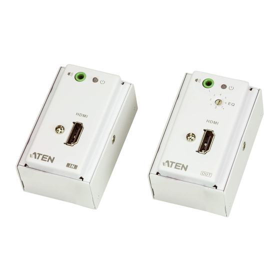
Page 12: Components
VE157 / VE607 / VE807 User Manual Components Front View (Transmitter) VE607T VE157T VE807T Component Description Video IN Port The cable from your VGA / DVI / HDMI source device is plugged in here. Power LED The Power LED lights green to indicate that the unit is receiving power. -
Page 13: Rear View (Transmitter / Receiver)
Introduction Rear View (Transmitter / Receiver) Component Description Line IN/OUT (VE157) The Cat 5e cable that connects the Transmitter and Receiver units plugs in here. The Cat 5e TMDS Port (VE607 / VE807) connection between these ports transmits video and audio signals. - Page 14 VE157 / VE607 / VE807 User Manual This Page Intentionally Left Blank...
-
Page 15: Hardware Setup
For convenience and flexibility, the VE157 / VE607 / VE807 can be mounted on the wall, ceiling, floor or any surface of your preference. The dimensions of the VE157 / VE607 / VE807 are made to fit an area equal to a standard wall plate. -
Page 16: How To Supply Power
VE157T / VE607T / VE807T or VE157R / VE607R / VE807R rear panel; and then, to a power outlet to supply power to your VE157 / VE607 / VE807. Follow the steps described below: 1. Cut off the connector end of the power adapter. - Page 17 Hardware Setup Note: The device can be damaged if incorrectly paired wires are inserted into the terminal block. A voltmeter is one of the tools used to measure an exposed wire’s polarity (i.e., +9V or GND). 4. Connect and snap the Terminal Block Connector into the 2-pin Terminal Block located on either the Transmitter or Receiver unit’s rear panel.
-
Page 18: Wall Mounting
VE157 / VE607 / VE807 User Manual Wall Mounting At this point, the site(s) for wall-mounting the VE157 / VE607 / VE807 should be ready. Note that there are cable connections to be made at the rear panel of the units – see Hardware Installation. -
Page 19: Hardware Installation
Hardware Installation After mounting the VE157 / VE607 / VE807 Transmitter and Receiver units, you can conveniently connect the VE157 / VE607 / VE807 wall plate covers to your input/output equipment. Refer to the installation diagram on the following page (the numbers in the diagrams correspond to the steps below), and do the following: 1. - Page 20 VE157 / VE607 / VE807 User Manual...
-
Page 21: Basic Operation
The quality of the video signal can decrease with distance. To adjust the video quality, do the following: VE157 – Use the Manual Gain Control switch by turning the knob clockwise to increase the video signal, or turning the knob counter- clockwise to decrease the video signal –... - Page 22 VE156 / VE606 / VE806 User Manual This Page Intentionally Left Blank...
-
Page 23: Appendix
Appendix Safety Instructions General Read all of these instructions. Save them for future reference. Follow all warnings and instructions marked on the device. This product is for indoor use only. Do not place the device on any unstable surface (cart, stand, table, etc.). If the device falls, serious damage will result. - Page 24 VE157 / VE607 / VE807 User Manual If an extension cord is used with this device make sure that the total of the ampere ratings of all products used on this cord does not exceed the extension cord ampere rating. Make sure that the total of all products plugged into the wall outlet does not exceed 15 amperes.
-
Page 25: Technical Support
Appendix Technical Support International For online technical support – including troubleshooting, documentation, and software updates: http://eservice.aten.com For telephone support, see Telephone Support, page iii: North America Email Support support@aten-usa.com Online Troubleshooting http://eservice.aten.com Technical Documentation Support Software Updates Telephone Support... -
Page 26: Supported Aten Products
VE157 / VE607 / VE807 User Manual Supported ATEN Products The VE157 / VE607 / VE807 Transmitter and Receiver can each be used separately with other VGA/DVI/HDMI extenders, as follows: VE157 VE022 VE170 VS1204T VS1208T VE607 VE600A VE807 VE800A VS1804T... -
Page 27: Specifications
Appendix Specifications Function VE157T VE157R Connectors Video In 1 x HDB-15 Female (Blue) Video Out 1 x HDB-15 Female (Blue) Audio In 1 x 3.5mm Stereo Jack (Green) Audio Out 1 x 3.5mm Stereo Jack (Green) Power 1 x RJ-45 Female (Silver) Power 1 x Terminal Block (Green) Line In... - Page 28 VE157 / VE607 / VE807 User Manual Function VE607T VE607R Connectors Video In 1 x DVI-D Female (White) Video Out 1 x DVI-D Female (White) Audio In 1 x 3.5mm Stereo Jack (Green) Audio Out 1 x 3.5mm Stereo Jack (Green)
- Page 29 Appendix Function VE807T VE807R Switch EQ Switch 1 x Knob Video 1080p @ 60 Hz (40m) 1080i @ 60 Hz (60m) Power Consumption DC 9V, 2.9W Environment Operating Temp. 0–50ºC Storage Temp. -20–60ºC Humidity 0–80% RH, Non-condensing Physical Housing Metal Properties Weight 0.17 kg...
- Page 30 CAD Drawings VE157T...
- Page 31 VE157T...
- Page 33 CAD Drawings VE157R...
- Page 34 VE157R...
- Page 36 CAD Drawings VE607T...
- Page 37 VE607T...
- Page 38 VE607T...
- Page 39 CAD Drawings VE607R...
- Page 41 VE607R...
- Page 42 CAD Drawings VE807T...
- Page 43 VE807T...
- Page 44 VE807T...
- Page 45 CAD Drawings VE807R...
- Page 46 VE807R...
- Page 47 VE807R...
-
Page 49: Limited Warranty
What is covered by the Limited Hardware Warranty ATEN will provide a repair service, without charge, during the Warranty Period. If a product is detective, ATEN will, at its discretion, have the option to (1) repair said product with new or repaired components, or (2) replace the entire product with an identical product or with a similar product which fulfills the same function as the defective product.
Need help?
Do you have a question about the VE157 and is the answer not in the manual?
Questions and answers