
Related Manuals for Peak Scientific MS Bench Series


Summary of Contents for Peak Scientific MS Bench Series
- Page 1 MS Bench (All Models) User Manual MS Bench (All Models) User Manual Rev 6 RSID 3023 EN 31/03/20...
-
Page 2: Table Of Contents
Contents Change History How to use this Manual Intended Use of Equipment Warranties and Liabilities Safety Notices Symbols Safety Notice to Users Weight Loading & Stability Declaration of Conformity Environmental Declaration Technical Specification Technical Specification Unpacking Fittings Kit Contents Installation Generator Environment Generator Overview General Dimensions SCI 1, G SCI 1 and G SCI 2... -
Page 3: Change History
Users can refer to the contents page to find the relevant information. Please review each of the following sections carefully. Thank you for selecting Peak Scientific to meet your gas generation needs, and should you require any further assistance or support please do not hesitate to contact Peak Scientific or the Peak Partner from which you purchased your generator. -
Page 4: Warranties And Liabilities
Warranties and Liabilities 1. The Company warrants that it has title to the Goods. 2. Subject to the provisions of this clause the Company warrants that the Goods shall comply in all material respects with any specification referred to in the Order Confirmation (as the same may be amended) and shall, subject thereto, be free from defects in material and workmanship for the lesser of a period of twelve months from the date of delivery or thirteen months from the date of dispatch... -
Page 5: Safety Notices
If the user employs an operating procedure, item of equipment or a method of working which is not specifically recommended by Peak Scientific, the user must ensure that the equipment will not be damaged or become hazardous to persons or property. -
Page 6: Weight Loading & Stability
Weight Loading & Stability Additional weight added to product either on top surface or within cabinet must not exceed the following maximum combined total: MS Bench SCI 1 : 272 Kg MS Bench G SCI 1: 215 Kg MS Bench SCI 2 : 272 Kg MS Bench G SCI 2: 206 Kg Failure to adhere to these values could lead to injury and or damage to... -
Page 7: Declaration Of Conformity
Declaration of Conformity Peak Scientific Instruments Ltd. Fountain Crescent, Inchinnan, Renfrewshire, PA4 9RE Declare that: Equipment: Bench and Nitrogen Generator Bench Models: MS Bench SCI 1, MS Bench G SCI 1, MS Bench SCI 2 & MS Bench G SCI 2 To which this declaration relates, is in conformity with the applicable EC directives, harmonized standards, and other normative requirements. -
Page 8: Environmental Declaration
WEEE (Waste of Electrical and Electronic Equipment) Directive 2012/19/EU. These obligations are being met within the B2B compliance group. Peak Scientific Instruments Ltd, herewith confirm that as a manufacturer of articles we conform to the European Parliament and Council Directives, 2011/65/EU for the original... -
Page 9: Technical Specification
Technical Specification Environment MS Bench SCI 1 MS Bench G SCI 1 Minimum Operating Ambient Temperature 5°C (41°F) Maximum Operating Ambient Temperature 30°C (86°F) Maximum Altitude 2000 m Maximum Relative Humidity 80% Non-Condensing Minimum Storage Temperature* -20°C (-4°F) Maximum Storage Temperature* 60°C (140°F) *NOTE –... -
Page 10: Technical Specification
Technical Specification Environment MS Bench SCI 2 MS Bench G SCI 2 Minimum Operating Ambient Temperature 5°C (41°F) Maximum Operating Ambient Temperature 30°C (86°F) Maximum Altitude 2000 m Maximum Relative Humidity 80% Non-Condensing Minimum Storage Temperature* -20°C (-4°F) Maximum Storage Temperature* 60°C (140°F) *NOTE –... -
Page 11: Unpacking
Check ‘SHOCKWATCH’ and ‘TIP-N-TELL’ labels for signs of rough handling prior to unpacking. Any damage should be reported immediately to the carrier and Peak Scientific or the Peak Partner from where the unit was purchased. Follow the unpacking instructions posted on the side of the crate. It will require two people to remove the unit from the shipping crate and to manoeuvre the generator to the desired location. -
Page 12: Fittings Kit Contents
Fittings Kit Contents Supplied in the Fittings Kit are all the fittings required to connect the generator to the application. The contents of the Fittings Kit are as follows: ” Teflon Tubing x 3m* 2. 5/16" Teflon Tubing x 3m* 3. -
Page 13: Installation
Installation Generator Environment The generator is designed for indoor use only. It should be installed adjacent to the application it is supplying. If this is not convenient then the unit can be sited elsewhere, however, consideration should be made of the lengths of pipe runs as pressure drops can result from extended runs of pipe. -
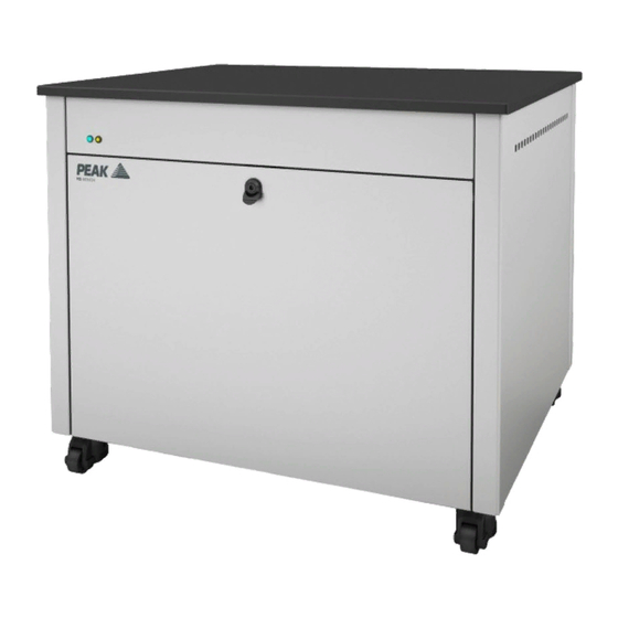
Page 14: Generator Overview
Generator Overview General Dimensions SCI 1, G SCI 1 and G SCI 2 914 mm / 36” 787 mm / 31” General Dimensions SCI 2 787 mm / 31” 1040 mm / 41” The generator must always be placed on a flat, level surface. Failure to do so will affect the performance of the generator. -
Page 15: Ms Bench G Sci 1 Rear Connections
MS Bench G SCI 1 Rear Connections IEC Power Inlet Power Switch Drain Outlet Curtain Outlet Source Outlet Exhaust Outlet Ensure all inlets and outlets are connected to correct sources and applications WARNING All Connections should only be carried out by trained personnel WARNING Generator must be switched off and unplugged prior to any cleaning or maintenance operations... -
Page 16: Ms Bench Sci 1 Rear Connections
MS Bench SCI 1 Rear Connections IEC Power Inlet Power Switch MS Bench SCI 1 Unit Controls Fan Power LED Page 16... -
Page 17: Ms Bench G Sci 2 Rear Connections
MS Bench G SCI 2 Rear Connections IEC Power Inlet Power Switch Drain Outlet Curtain Outlet Source Outlet Exhaust Outlet Ensure all inlets and outlets are connected to correct sources and applications WARNING All Connections should only be carried out by trained personnel WARNING Generator must be switched off and unplugged prior to any cleaning or maintenance operations... -
Page 18: Ms Bench Sci 2 Rear Connections
MS Bench SCI 2 Rear Connections IEC Power Inlet Power Switch MS Bench SCI 2 Unit Controls Fan Power LED Page 18... -
Page 19: Drain Connection (Ms Bench G Sci 1 & G Sci 2 Only)
Drain Connection (MS Bench G SCI 1 & G SCI 2 Only) Fit the 6mm push fit fitting to the drain port located on the output panel. Tighten using a 16mm or 5/8” spanner. Use the 6mm tubing to connect this to a suitable drain connection or container. -
Page 20: Electrical Connection
Electrical Connection Connect the generator to an appropriate single-phase supply, refer to the generator serial plate for input specification and ensure your supply matches the requirements. If an appropriate mains power cords is not supplied or a substitute one is used then ensure that all components of it the plug, cord and connector have adequate ratings for the generator and appropriate approvals for the country of use. -
Page 21: Start-Up Sequence (Ms Bench G Sci 1 & G Sci 2 Only)
Start-Up Sequence (MS Bench G SCI 1 & G SCI 2 Only) Before the Generator is connected to the application, the Generator should be operated in isolation (i.e. not connected to the application) for thirty minutes. This is to ensure any impurities present are purged from the system. -
Page 22: Connecting To The Application (Ms Bench G Sci 1 & G Sci 2 Only)
⁄ ” I/D). Tubing and fittings not supplied in the fittings kit. > 40 metres: Please contact Peak Scientific with the relevant distance and we will calculate the flow resistance and the tubing size required. A combination of ”/ ⁄... -
Page 23: Normal Operation (Ms Bench G Sci 1 & G Sci 2 Only)
Unusual Operation (MS Bench G SCI 1 & G SCI 2 Only) If at any time the generator begins to emit excessive noise or vibration, then it should be switched off and you should contact Peak Scientific or the Peak Partner from which the generator has been purchased. -
Page 24: Fan Power Led (Ms Bench Sci 1 & Sci 2 Only)
Fan Power LED (MS Bench SCI 1 & SCI 2 Only) The MS Bench Bench is fitted with a fan power LED on the front panel. The LED should be illuminated when the table is supplied with power. This is indication that the internal cooling fans are being supplied with power, and are running correctly. -
Page 25: Safe Operation Of Pump Tray (Ms Bench Sci 1 Only)
Safe Operation of Pump Tray (MS Bench SCI 1 Only) For safe installation or removal of roughing pumps, we recommend use of the sliding function of the pump tray, as shown below. This should only be attempted once the Mass Spec has been positioned on top of the table. -
Page 26: Safe Operation Of Pump Tray (Ms Bench Sci 2 Only)
Safe Operation of Pump Tray (MS Bench SCI 2 Only) For safe installation or removal of roughing pumps, we recommend use of the sliding function of the pump tray, as shown below. This should only be attempted once the Mass Spec has been positioned on top of the table. -
Page 27: Service Requirements (Ms Bench G Sci 1)
Service Requirements (MS Bench G SCI 1) Service Schedule Purchase Interval Component Visit 12 Months MS Bench G SCI 1 Annual Maintenance Kit* www.peakscientific.com/ordering 4 Years MS Bench G SCI 1 Year 4 Service Kit* www.peakscientific.com/ordering Service Requirements (MS Bench G SCI 2) Service Schedule Purchase Interval Component... -
Page 28: Service Indication (Ms Bench G Sci 1 & G Sci 2)
Service Indication (MS Bench G SCI 1 & G SCI 2) The generator has the following Service Indication Stages:- Stage 1 Once either compressor requires a service the LED indicator (yellow) on the front of the generator will illuminate. This is to make the user aware that a service of the generator is due and should be planned at the earliest convenience. -
Page 29: Peak Protected
Peak Protected With Peak Scientific you invest in not only a product but peace of mind. With a network of certified Peak engineers stationed throughout the globe, Peak’s rapid response team are never far away and our commitment is to keep your generator running day in, day out, protecting your laboratory workflow. -
Page 30: Cleaning
Cleaning Clean the outside of the generator only using warm soapy water and a clean damp cloth. Ensure all excess fluid is thoroughly removed from the cloth prior to use. Cleaning should only be undertaken with the power switched off and the power cord removed from the rear of the generator. -
Page 31: Troubleshooting (Ms Bench G Sci 1 & G Sci 2)
Troubleshooting (MS Bench G SCI 1 & G SCI 2) Problem Possible Solution • Ensure power cord is plugged into the Generator and that the power socket is turned on. The Generator will not switch on and the power switch does not illuminate. - Page 32 See our enclosed Peak [Protected] leaflet for further information. Important! You have 1 month to register your Peak Scientific product from the date of installation. Once registered the warranty will be honoured for a period of 12 months. If you wish to defer the installation of your generator, you must notify Peak Scientific immediately by emailing warranty@peakscientific.com.
- Page 33 Page 33...
- Page 34 Page 34...
- Page 35 Page 35...
- Page 36 Peak Scientific has highly trained, fully certified Field Service Engineers located in over 20 countries across every continent around the world. This allows us to provide an industry-leading rapid response service to our customers. With [Peak Protected], your laboratory’s productivity becomes our top priority.
Need help?
Do you have a question about the MS Bench Series and is the answer not in the manual?
Questions and answers