
Related Manuals for Bartec Syscom MR3000 Series


Summary of Contents for Bartec Syscom MR3000 Series
- Page 1 User Manual MR3000SB Firmware Version 2.0.x © SYSCOM Instruments SA Rue de l'Industrie 21 1450 Sainte-Croix Switzerland Tel +41 24 455 44 11 Fax +41 24 454 45 60 sales@bartec-syscom.com www.bartec-syscom.com...
-
Page 2: Table Of Contents
- 2 - CONTENTS 1. INTRODUCTION....................5 1.1 Features........................6 1.2 Specifications......................6 1.3 Applications......................6 2. HARDWARE....................7 2.1 Mechanical Drawing – Overview................7 2.2 Connectors......................8 2.2.1. Power........................9 2.2.2. LAN 1........................9 2.2.3. LAN 2........................10 2.2.4. GPS (optional)......................10 2.2.5. Relays........................10 2.3 Status LEDs......................10 2.3.1. List of errors and warnings...................10 2.4 Opening the Lid......................11 2.4.1. - Page 3 - 3 - 4.1.3. Alerts........................31 4.1.4. Measurements settings..................32 4.1.5. Site installation.....................33 4.2 Power Options......................34 4.2.1. Internal Battery.....................34 4.2.2. AC Power......................35 4.2.3. DC power......................35 4.3 Additional services....................35 4.3.1. Embedded SFTP server..................35 5. The Web User Interface (WebUI)..............38 5.1 Start.........................38 5.1.1. Manual recording....................38 5.1.2.
- Page 4 - 4 - 5.6 Master functionality....................71 5.6.1. Config / Status and Master/slave configuration............72 5.6.2. Common Trigger....................72 5.6.3. Common Alarm 1 and 2..................74 5.7 Recording List......................74 5.8 System warning......................76 5.9 Rest API........................77 6. Available spare parts and accessories............78 Appendix A: SAFETY INSTRUCTIONS............79 MR3000SB_v20x_rev1.odt subject to technical change without notice...
-
Page 5: Introduction
In case the internet connection is available, it is possible to connect the MR3000SB to the SCS cloud software (scs.bartec-syscom.com), in order to visualize and post-process data coming from different devices. It is also possible to remotely change the most important parameters of the instruments. -
Page 6: Features
Features Main features are: Compact unit with integrated sensor, digital recorder, battery and wired connectivity ARM/DSP Technology Daisy chain connection Tri-axial MEMS accelerometers Removable 4 GB SD-Card storage (up to 32 GB) Internal battery ... -
Page 7: Hardware
HARDWARE Mechanical Drawing – Overview Figure 2.1.1. Mechanical drawings of the MR3000SB: top view (a), front view (b). The external case is identical to MR3000SB. -
Page 8: Connectors
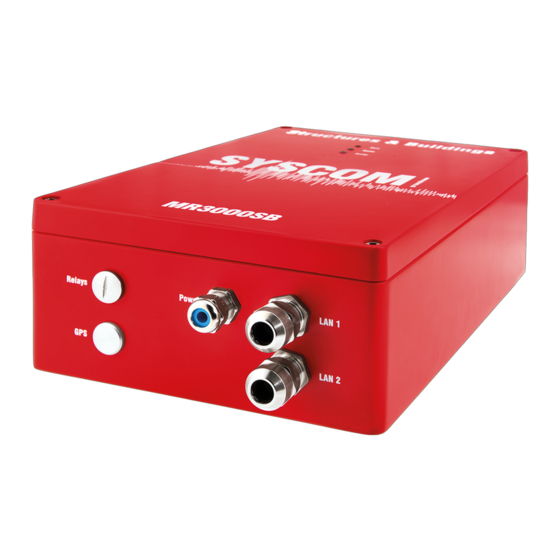
Connectors The MR3000SB provides rugged cable glands and caps depending on the version, as it is shown in Figure 2.2.1: Power for 100-240VAC power supply or DC/DC (10-36 VDC). • Relays for relay outputs. • GPS to connect an external GPS antenna. If the GPS antenna is not ordered, then the •... -
Page 9: Power
c) kit 2 FO daisy chain d) kit 2 LAN daisy chain e) kit FO/LAN daisy chain Figure 2.2.1. View of the different panel mounts of the MR3000SB showing the sockets for Relays, Power, LAN1, LAN2 and GPS. 2.2.1. Power Here you connect the MR3000SB to: the main power (100-240VAC, 50-60 Hz) in case the AC version has been purchased •... -
Page 10: Lan 2
If the kit LAN has been ordered, the SB interfaces to a standard 10/100-BASE LAN. 2.2.3. LAN 2 It is present only in case of kit FO daisy chain, kit LAN daisy chain or kit FO/LAN. 2.2.4. GPS (optional) In case the GPS kit has been ordered, here you connect to an appropriate GPS module for time synchronization. -
Page 11: Opening The Lid
No more free space ERROR • Lifetime is less than 20% WARNING • Lifetime expired ERROR • Battery Battery is not powered WARNING • Voltage Please refer to Section 5.3.13 • Test pulse Test pulse did not succeeded WARNING • Opening the Lid WARNING –... - Page 12 Figure 2.4.1. Internal view of the MR3000SB with AC power.
-
Page 13: Internal Display
Figure 2.4.2. Internal view of the MR3000SB with DC power and relay terminals. 2.4.1. Internal display The LCD of the MR3000SB shows the most important settings and parameters. In particular, there are two types of screen, that are changing constantly. The first one, as can be seen in Figure 2.4.3a, indicates general parameters related to the MR3000SB: LINE 1. -
Page 14: Mems Acceleration Sensor
LINE 2. IP address of the instrument. LINE 3. Values set for the trigger on the three axes. When trigger is 'disabled' or its mode is 'STA/LTA', this is clearly shown on the LCD display LINE 4. Number of events recorded on the SD card. Figure 2.4.3. -
Page 15: Sd Flash Card
2.4.3. SD Flash Card The MR3000SB contains an SD-card slot. The SD Flash Card in this slot is used to store the recordings. To remove the card, you have to push it down, it will then pop-up. NOTE: Ensure the MR3000SB is turned off before removing and re-inserting the SD Card. Figure 2.4.4. -
Page 16: Battery
2.4.5. Battery In the SB, the internal battery guarantees about 60 hours of autonomy in stand-alone mode, 40 hours in normal mode with communication with other units. It is a 12 V battery, 12 Ah. 2.4.6. ST connectors In the case the standard FO version is ordered, then a cable with ST connectors is connected to the point 6 in Figure 2.4.1. -
Page 17: Relays
2.4.8. Relays The relays (optional) can be configured in the software (see section 4.4.7). For an accurate electric scheme, look Figure 2.4.8. Figure 2.4.8. Terminal for relays (a) and electric scheme (b). 2.4.9. AC/DC converter In Figure 2.4.9 it is possible to see the hardware structure and terminals related to the AC/DC converter. -
Page 18: 2.4.10. Dc Board
Figure 2.4.9. AC/DC converter. 2.4.10. DC board In case of DC version, the AC/DC converter is replaced by a dedicated board for an external DC power (see Figure 2.4.10). Figure 2.4.10. DC board. 2.4.11. Terminal label To better understand the terminals and the electric connection of the relays and the AC power, a label with this information has been placed on the cover of the MR3000SB. - Page 19 Figure 2.4.11. Label with information on the terminals of relay and power for: a) MR3000SB with AC power; b) MR3000SB with DC power. Figure 2.4.12. Axis orientation in case of horizontal and vertical installation.
-
Page 20: 2.4.12. Axis Orientation
2.4.12. Axis orientation The axis orientation of the MR3000SB depends if the installation is vertical (against a wall) or horizontal (on the ground). In the Figure 2.4.12 the different configurations are shown. 2.4.13. Installation For a fixed installation of the SB, it is possible to directly fix the SB or to use a mounting plate. In the first case, the holes (number 1 in the Figures 2.4.13 and 2.4.14) close to the screws (number 2 in the same figures) can be used. - Page 21 Figure 2.4.15. Drawing of the SB. The values are in mm. In case of a mounting platform, the same holes are used to fix it to the MR3000SB. This application must be preferred in cases where the surface of installation is not perfectly smooth. In Figure 2.4.16 it is possible to have all the information about the distances.
- Page 22 Figure 2.4.16. Drawing of the mounting plate related to the MR3000SB. The values are in mm. Figure 2.4.17. Screws for the installation of the MR3000SB.
-
Page 23: Set-Up Of The Mr3000Sb
SET-UP of the MR3000SB First of all, please connect the MR3000SB to the main power or to a DC power, depending on the version purchased. In case no power is provided, the internal battery can guarantee an autonomy of about 40 hours. You have to open the MR3000SB and close the fuse (F1), in order to switch on the device. -
Page 24: Wired Connection Without Router
Figure 3.1.1. FO cables with ST connectors. After connecting all the SB in the network to a router, after few seconds it assigns an IP address to all the MR3000SB. The DHCP feature of the router makes sure your PC has acquired an IP address in the same subnet and communication between MR3000SB and PC is possible. -
Page 25: Connecting To The Mr3000Sb In The Field (Remote Connection)
Figure 3.1.2. Settings of the LAN port on the personal PC. Connecting to the MR3000SB in the field (remote connection) For a remote connection (from your office to the SB at site) you need Internet access and you have to enable the OpenVPN or DDNS service. You can use an existing Internet access point at site (DSL, cable TV line, ...) and you simply connect the MR3000SB with the router using the LAN/FO cable –... - Page 26 3. Link the MR3000 in one project 4. Click on the recorder name to access its setting More details can be found at scs.bartec-syscom.com or at the dedicated webpage on the Bartec Syscom website. Please contact support@bartec-syscom.com for any additional information.
-
Page 27: Operating With The Mr3000Sb
For the vibration monitoring of a structure, several SB are necessary, depending on the structure dimension and typology. Please contact info@bartec-syscom.com to have more information. AC power is normally available at all the sites, and the internal battery ensures monitoring continuity if power is lost. - Page 28 Figure 4.1.1. Setting of a fix IP address on a personal PC or laptop. Figure 4.1.2. Assignment of the IP address to a MR3000SB, in case of a local network.
-
Page 29: Network Settings
Master. In this way, it is possible to perform common sampling, common trigger and common alarm. All the details are given in Section 5.6. Please contact Syscom at info@bartec- syscom.com to have an application note dedicated to the preparation of a local network. - Page 30 Figure 4.1.4. Subsection dedicated to the setting of the common trigger.
-
Page 31: Alerts
Figure 4.1.5. Subsection dedicated to the common alarms. Successively, in the Common Alarm section, you define the conditions for the voting logic. The procedure is exactly the same as for the common trigger. Make sure to activate the Common Alarm in the tab Contacts to get a message if there is a common alarm. 4.1.3. -
Page 32: Measurements Settings
4.1.4. Measurements settings First the sampling frequency must be set up, then the trigger level. In the example, the trigger level is set at 10 mg on X and Y axes while 50 mg for the Z axis. The trigger is activated if one of the three axes exceed the respective threshold. -
Page 33: Site Installation
Successively, the alarm parameters should be defined. In this case, the alarm 1 threshold is fixed at 8 mg on the 3 axes. In addition, a user-defined alarm frequency-amplitude based (similar to an OBE-operating basis earthquake or SSE-Safe shutdown earthquake reference spectrum). For further details, please look at Subsection 5.4.3. -
Page 34: Power Options
Figure 4.1.11. Screen dedicated to the status of the MR3000SB. Status tab (for all the details please refer to Section 5.2) should be open to check: 1) The status of the supply power; The free space on the SD card and its lifetime; Now the unit is operational. -
Page 35: Ac Power
4.2.2. AC Power In this case, you can simply connect the MR3000SB to the main power. This solution is highly recommended. 4.2.3. DC power On request, the MR3000SB may be powered also by DC power, as for example external power as solar panels. - Page 36 In the Main tab enter an account name (whatever you want to name this connec- tion). In the field host you enter the IP address of the SB (real address for direct connection, VPN address for remote connection login and password as mentioned above.
- Page 37 To quickly retrieve ALL the data from the SB, you navigate on the left hand panel (PC) to the directory of this SB, on the right hand panel you navigate to the directory “user”. Then you open the menu Tools and select Sync Directories & Subdirectories… As shown in the picture below, the tool has already pre-selected the desired action, i.e.
-
Page 38: The Web User Interface (Webui)
The Web User Interface (WebUI) Once the connection with the MR3000SB is established, and the IP address of the MR3000SB is known, the Web user interface (WebUI) must be opened. Just launch your favorite Web browser, and enter the IP address of the SB in the address bar. Depending on your Web browser, you may have to enter the letters “http://”... -
Page 39: Trigger Recording
In the table Recording list below all recordings currently stored on the SD card are shown. New files show up after clicking on the refresh icon. Double-clicking on a file starts the download of the file and the waveform is shown using the PC software EAWlight (only available for WINDOWS PCs). - Page 40 The Maximum length setting allows you to choose the maximum length of an event file. If this limit is reached, the SB closes the file. If the SB is still triggered it will start recording a new file. The maximum value is 1800 s. Each channel (X, Y horizontal and Z vertical) has its own trigger threshold level that is set-up in the section Level.
-
Page 41: Timed Recording
STA/LTA is a trigger algorithm usually used in the field of weak-motion seismology. The STA/LTA continuously calculates the average values of the absolute amplitude of a seismic signal in two consecutive moving-time windows. The short time window (STA) is sensitive to seismic events while the long time window (LTA) provides information about the temporal amplitude of seismic noise at the site. -
Page 42: Background Recording
Figure 5.1.4. Timed recording interface. 5.1.4. Background recording In background recording mode the SB records the peak values within a given time window. Please note that event recording is not affected by the peak recording – both services may run simultaneously. -
Page 43: Status
Status This page displays information about the SB. The page is updated automatically. ID contains: • Name of the MR3000SB (by default this is mr3000, followed by a dash and its serial number). You may change the name, according to your needs (see Section 5.4.1). Comment, for example a description of the location where you have installed the SB. -
Page 44: System
Dynamic DNS shows 5 different states: up: service is active starting: service is starting up error_server: communication problem with the server updated: the service has updated the DNS address. In this case an additional field with the WAN address that is related to the DNS entry is shown down: service is not active. -
Page 45: Sd Card
5.3.1. SD Card This subsection shows the capacity of the memory card and the amount of memory available. Moreover, and indication of the remaining lifetime is displayed. You can format the memory SD card with the relative button: this erases ALL the data memorized on the card. - Page 46 As a second option, you may adjust the clock at once with an NTP server using the Internet connection. In the pop-up windows you have to set-up appropriate NTP servers. Alternatively the time can be set manually, and this works in every situation (i.e. without connection to the Internet).
-
Page 47: Lan
Figure 5.3.2. Subsection dedicated to the time synchronization in case of mode “Disabled” and mode “Network (NTP)”. 5.3.3. In this subsection, the settings for the Ethernet port (interface for wired connection) are shown. Mode is as follows: DHCP means that the SB will try to get an IP address by sending DHCP requests. Select this option if you connect the SB to a network with a DHCP server. -
Page 48: Ddns
The Netmask is 255.255.255.0 by default, and should remain like this except if you know exactly what you're doing. The Gateway address must be filled if you connect the SB on a network. This is the IP address of the router. Same thing for the Nameserver. -
Page 49: Openvpn
dyndns no-ip dyndnsit changeip sitelutions Figure 5.3.4. Subsection dedicated to the DDNS. 5.3.5. OpenVPN VPN stands for Virtual Private Network. With this service, you will be able to communicate with the SB when it is out in the field where it neither has a public (accessible from the WEB) nor a static (not changing) IP address. -
Page 50: Mail
Communication with the VPN service needs an Internet connection – check with the PING function as described in chapter 5.3.10. The data stream for interactive communication through the WebUI are routed via the OpenVPN server. The communication between your PC and the SB is encrypted. The other data (FTP push, NTP time synchronization, E-Mail, Firmware-upgrade) are not routed through the VPN tunnel, but use the normal Internet access. -
Page 51: Ftp Send
NOTE: The quality of the mail service varies with the provider. Figure 5.3.6. Subsection dedicated to the mail. 5.3.7. FTP send If this service is enabled, the SB will periodically connect to a remote FTP server and copy its data to it. - Page 52 In Push mode the SB will push a new event file to the FTP server as soon as recording of the file is done. The current background file may be updated continuously on the FTP server. In User parameters > Advanced settings – see chapter 5.4.8 - you specify how often the current background file is updated on the FTP server.
-
Page 53: Scs Cloud
The MR3000 can be connected to the SCS (Syscom Cloud Software) to easily visualize the data coming from it. The web address of the cloud software is http://scs.bartec-syscom.com. The MR must have internet connection to communicate with the SCS. Please see the related tutorial video “LINK A MR3000 TO THE SCS”... -
Page 54: Authentication
For any additional information on the SCS cloud software, please refer to the dedicated page on website or visit http://scs.bartec-syscom.com. 5.3.9. Authentication Here you can change the password of the SB. The password is used for the WebUI access and for the SFTP service (see chapter 4.3.1). -
Page 55: 5.3.10. Upgrade
“Upgrade from files”. If the extension .txt is automatically added by your operating system (e.g. Windows), the please delete it. NOTE: It is recommended to upgrade the MR3000 at the end of a monitoring session. Please contact support@bartec-syscom.com for further clarifications. Figure 5.3.10. Subsection dedicated to the Upgrade. -
Page 56: Maintenance
5.3.11. Maintenance Here you may generate a report of the system to make further investigations in case of trouble. The report is automatically downloaded to your PC. NOTE: The log files and other variables used to generate the Diagnostic report are in volatile memory, do not switch of the SB before the report is generated. -
Page 57: 5.3.12. Sensor
Figure 5.3.12. Subsection dedicated to the import of user parameters. 5.3.12. Sensor Inside the current section, there is one subsection dedicated to the sensor of the MR3000SB, which is an internal triaxial accelerometer. Inside this section, the sensor model, the type, unit of measure and the serial number are indicated. Figure 5.3.13. -
Page 58: Monitoring
With modify settings you can modify the unit of measure of the sensor. It is possible to select metric or imperials units, in particular mg (default value) or m/s2 or in/s2. NOTE: if you do not want to change the settings please click on CANCEL, because otherwise the MR will reboot. -
Page 59: User Parameters
User Parameters In this part you set-up the parameters related to Alerting and the general parameters that are not related to data acquisition. 5.4.1. General Here you can modify the Name (ID) of the SB (by default mr3000, followed by a dash and the serial number UID of the SB) and the Comment string. -
Page 60: Alarm
Figure 5.4.2. Subsection dedicated to system acquisition. 5.4.3. Alarm The alarm service checks if the vibration exceeds the defined alarm threshold levels. In this case, the notification service of the MR3000 sends an e-mail to the people listed in contacts where Alarm 1 or Alarm 2 have been checked (see chapter 5.4.4). - Page 61 It is possible to define two levels of alarms: alarms 1 and alarm 2. They can be configured completely independently. In the field “Based on”, the alarm can be activated on the trigger or on the background recording. In the following, let us analyze the two situations separately. Trigger recording Figure 5.4.3 shows the possibilities for the choice of the alarm limit, when the alarm has been selected on the trigger recording.
- Page 62 points for each channel. A maximum number of 8 points can be set for each channel. Moreover, each channel can be set completely independently, meaning that X can have 2 points, Y can have 4 points and Z no points. The button “Restore” allows to reset the name and the values defined. NOTE: If an alarm is defined on a user-defined norm, it is not possible to set the trigger value higher than the alarm threshold.
- Page 63 If the user defined norm is activated, in the section Start → Background recording, a mode including the dominant frequency must be also activated (Subsection 5.1.4). Figure 5.4.6. Configuration of the alarms causing a warning. Figure 5.4.7. a) Setting of the background recording; b) Warning message caused by the definition of the alarm as in Fig.
-
Page 64: Notification
NOTE: A configuration like in Fig. 5.4.6 is not correct because the MR3000 is not able to save the vector sum and the dominant frequency at the same time (Subsection 5.1.4). For example, if the option “Peak + Dominant Frequency” has been selected, then a warning indicating that Alarm 1 cannot happen is shown (Fig. - Page 65 Contacts In this subsection, it is possible to add Contacts for the notification service. Contacts are people who receive notification from the MR3000. To add a new contact click on the Add button. To edit a contact, just click the corresponding line. Clicking the Del button will delete the corresponding contact.
- Page 66 Trigger event • Alarm 1 • Alarm 2 • Daily messages • Test pulse • SD Card state of health • Battery state of health • In Fig. 5.4.10, two windows related to the different messages are shown. In case of Alarm 1, Alarm 2 and Daily message, the user can also add a comment, that will be displayed in the message.
-
Page 67: Daily Message
5.4.5. Daily message This service sends you an e-mail notification every day. You can set-up the Time when you wish to receive this notification. Some information is automatically appended: the number of events, the memory available, the lifetime of the SD-Card and the background mode. The recipients of this message are set-up in the section contacts –... -
Page 68: Relays
In Event recording settings you can choose between two file formats: XMR, the proprietary format prepared by Bartec Syscom for events. ASCII, a simple format where all the data recorded is put in a simple text file. It is convenient if you plan to use software like GNU Octave, Matlab or other commercial software to view and process your data. -
Page 69: View
In Background recording settings you can choose between two file formats: BMR, the proprietary format prepared by Bartec Syscom for background files. ASCII format In Traffic settings you can set-up how often the background files are pushed to the server, choosing a value included from 1 to 60 minutes. -
Page 70: Background
the line, with the same color but lighter shade, the envelope of the signal (with the true peaks) is drawn. The Vertical zooming, or simply zoom, is exactly what its name suggests. A value of 1 means no zooming; a value of 100 means that signal is multiplied by 100. Figure 5.5.1. -
Page 71: Master Functionality
Figure 5.5.2. Real-time visualization of background data. Master functionality To use this feature the option must be activated in one of the instruments – the Master. The other instruments are standard instruments – called Slaves. Communication in the network is handled by the Master. -
Page 72: Config / Status And Master/Slave Configuration
5.6.1. Config / Status and Master/slave configuration Here you define which MRs are part of the network. Simply add the IP-address of the MR. The Master itself must be included (simply check the itself box). The IP address of the Master could be shown as 127.0.0.1 (localhost) or as its own IP address (Figure 5.6.1). - Page 73 Figure 5.6.2. Subsection dedicated to the setting of the common trigger. Click on the Add button to set-up a new condition. Click in the Edit combination section the select box for the single MRs. In the column Name you may enter a mnemonic for this condition (e.g. MR in cellar).
-
Page 74: Common Alarm 1 And 2
5.6.3. Common Alarm 1 and 2 Common Alarm means that there is a voting logic for the alarms. Here you define the conditions for the voting logic. The procedure is exactly the same as for the common trigger. Make sure to activate the Common Alarm in the tab Contacts to get a message if there is a common alarm. - Page 75 software to visualize the data) installed, the file (peak or event) is shown immediately. You may use EAWlight to perform a Frequency Analysis (FFT) of the waveform and to print the waveform. You may select several files and then click on the Download button. The files are packed in a single Zip-File and transferred to the PC.
-
Page 76: System Warning
Figure 5.7.2. Subsection dedicated to the filters for the recording list. System warning In case there are anomalous settings about the parameters of the MR3000SB, warning or errors will be displayed in order to alert the user. For example, if the user does not activate the alarms but he wants to receive the mails also with notification of the alarm then, immediately after confirmed the operation with the “Apply”... -
Page 77: Rest Api
Figure 5.8.2. Automatic warning produced by the software. Rest API The REST API functionality have been added on the firmware 1.6. Please contact Bartec Syscom for more information at info@bartec-syscom.com. -
Page 78: Available Spare Parts And Accessories
Available spare parts and accessories In the following, a list of spare parts is shown. Battery (12V / 12 Ah) 74.21.1024 Backup battery (3V) 74.21.0018+ Fuse (1.6AT / 250V 5×20 mm) 74.15.0005+ SD card 4GB (SWISSBIT) 74.90.0035+ Mounting Plate + screws and bolts 13.00.0048 Kit GPS (cable, connector, GPS) 12.11.0201... -
Page 79: Appendix A: Safety Instructions
Appendix A: SAFETY INSTRUCTIONS Introduction Thank you for choosing this Bartec Syscom product. Before operating it, please read this manual thoroughly and retain it for future reference. Note - Before operating the product, please read "Safety information". - Pictures and illustrations used in this manual are for reference only and may differ from actual product appearance. - Page 80 - Unplug the mains plug and clean it regularly. If the plug is covered with dust and it picks up moisture, its insulation may deteriorate, which could result in a fire. Note - Do not use the supplied mains lead on any other equipment. - Do not pinch, bend or twist the mains lead excessively.
- Page 81 Disposal of the product Disposal of Old Electrical & Electronic Equipment (Applicable in the European Union and other European countries with separate collection systems) This symbol indicates that the product shall not be treated as household waste. Instead it shall be handed over to the applicable collection point for the recycling of electrical and electronic equipment.
Need help?
Do you have a question about the Syscom MR3000 Series and is the answer not in the manual?
Questions and answers