Table of Contents

Subscribe to Our Youtube Channel
Related Manuals for Bartec RLAnet 17-85G5-2123 Series


Summary of Contents for Bartec RLAnet 17-85G5-2123 Series
- Page 1 11-85G5-7D0002/B-EHT-10/2021 Monitoring device RLA Operation and Installation Manual Monitoring device for BARTEC water detection systems Type 17-85G5-2123**** Translation of the origin Operation and Installation Manual Language: EN...
-
Page 3: Table Of Contents
11-85G5-7D0002/B-EHT-10/2021 Table of Contents Product description ............5 9.6. Viewing the event log ............. 19 Safety regulations ............5 Operating states ............21 2.1. Intended use ..............5 10.1. Operating state Normal ..........21 2.2. Foreseeable misuse ............6 10.2. Operating state Leak ............21 2.3. -
Page 5: Product Description
With the integrated software of the RLA monitoring device, it is BARTEC GmbH assumes no liability for damages resulting from possible to establish an exact localisation of the leak that has the installation and use of the software, and in particular not for occurred. -
Page 6: Foreseeable Misuse
Assembly and operating instructions / EN 2.2. Foreseeable misuse The use of the RLA monitoring device is not permitted: CAUTION! CAUTION indicates a potentially imminent danger. If – outside of its intended use not avoided, minor injuries may result. – with non-approved or unintended components –... -
Page 7: Technical Data
11-85G5-7D0002/B-EHT-10/2021 3. Technical data General Connection Monitoring device for the detection and Alarm relay power connection, Type of control localisation of electrically conductive and non- Terminals leak sensor, RS485 (4 terminals) electrically conductive liquids 1 line, four digits with 7 segments respectively, Max. -
Page 8: Wiring Diagram
3.1. Wiring diagram Connection as a stand-alone system Connection of sensors, cables and plugs Monitoring device RLA SCR sensor line, PS sensor SCR sensor line, PS sensor Plug/plug-in coupling M12 (BARTEC item 05-0091-0054, item 05-0091-0055) Terminating plug (BARTEC Art. 05-0080-0161) - Page 9 11-85G5-7D0002/B-EHT-10/2021 Connection in the MODBUS network Connection of the RS485 line Monitoring device RLA HMI, such as PC RS485- Twisted pair cable, 2x 0.5 mm² Leitung 120R Termination resistance (optional) In the event of transmission errors, the optional use of a bus termination with R=120 Ohm or a data line Z0=120 Ohm is possible. Connection and switching situations Voltage Relay contact...
-
Page 10: Device Description
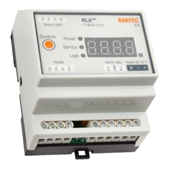
Assembly and operating instructions / EN 4. Device description Description of the display ---- no leak 4.1. Module description 12.3 leakage at 12 running meters line break no display no power present Scope of delivery 1 piece Monitoring device RLA 1 piece Data sheet/quick guide Type label... -
Page 11: Software Description
11-85G5-7D0002/B-EHT-10/2021 4.2. Software description Item Description Function Interface settings Communication settings for the (Comm Config) Sensor parameter settings Settings of the connected (induction line) sensors Date/time settings Date and time settings (clock) Leak monitoring area Display and control of leakage (monitor) monitoring Event storage area... -
Page 12: Functional Description
The Modbus communication parameters are described in the leak). supplementary documentation "RLAnet Modbus Communication Protocol". This is available at www.bartec.com. Keyword search If the leakage is still present, the message appears as described. for “RLA”. If the sensor cable breaks, the RLA generates a corresponding message on the display. -
Page 13: Assembly
The components and these assembly and operating instructions. surface to be glued onto must be dry, clean and largely free of dust. Fasten the sensor cable at 1m intervals with BARTEC fastening tape. 7.1. Mechanical assembly Do not fix the sensor cable directly to metal parts. -
Page 14: Commissioning
Assembly and operating instructions / EN 8. Commissioning 9. The service programme The “RLA_net_com” programme is the software communication In the application documents, the running meters of the SCR sensor cable and/or the PS point sensor, or PSO, which are interface of the RLA monitoring device and is displayed on a monitored by the RLA... -
Page 15: Starting The Service Programme
11-85G5-7D0002/B-EHT-10/2021 9.1. Starting the service programme The RLA_net_com programme is started by double-clicking on the EXE file. The installation will then begin. Link to the programme on the desktop: If prompted, click on the desired language to select it: The start screen is then displayed: Set basic parameters (factory settings) Serial number: COM1 Baud rate: 9600... -
Page 16: Setting The Interface, Creating A Connection To Rla
Assembly and operating instructions / EN 9.2. Setting the interface, creating a connection to RLA Software area Comm Config Figure 1 Comm Config programme area, communication interrupted Communication settings between the software and RLA can be set in the Com Config section. Values can be entered in the upper line relating to the interface (serial number), the speed (baud rate) and the position or the connected monitoring devices RLA with which the entire system is to be addressed (address). -
Page 17: Setting The Sensor Parameters
11-85G5-7D0002/B-EHT-10/2021 9.3. Setting the sensor parameters Software area Induction Line ATTENTION! Warning regarding the incorrect setting of RLAnet parameters Set parameters must match the installed components of the system. Please note the sensor length and number of sensors. For an accurate locating function, it is important to set the Induction Line Length and Black Line parameters to match the data from the sensor connected to the RLA The application parameters of the connected sensor (connection/length) are: Induction line length: ___ m... -
Page 18: Setting The Date And Time
Assembly and operating instructions / EN 9.4. Setting the date and time Software area Clock The RLA records the date and time. For a correct recording in the event log it is recommended to set the clock of the RLA to the actual time. -
Page 19: Viewing The Event Log
11-85G5-7D0002/B-EHT-10/2021 ATTENTION! Warning of unresolved leakage The RLA is reset by pressing the Confirm leakage button. The error message in the display is deleted. It is necessary to check the system for existing leaks! If necessary, arrange for the cause of the leak to be eliminated. - Page 20 Assembly and operating instructions / EN...
-
Page 21: Operating States
11-85G5-7D0002/B-EHT-10/2021 10. Operating states 10.1. Operating state Normal Click the "Start monitor" button to start the monitor mode. The Normal state indicates that no leak has been detected along the sensors and that there are no faults in the sensor wiring. The value of the "Success"... -
Page 22: Operation
Assembly and operating instructions / EN 11. Operation The installed system can be monitored for leaks while the RLA is in operation. A prerequisite is that the system has been professionally installed and commissioned. The RLA shows the current operating status of the system on the device and the software. -
Page 23: Maintenance
However, BARTEC recommends subjecting the entire leakage system to an inspection at least once a year. The SCR sensor cable and the PS/PSO point sensor are largely maintenance-free. BARTEC recommends checking the electrodes of the PS sensors and the optics of the PSO sensors to ensure they are clean and free of grease. Clean the electrodes and the optics with alcohol or a degreasing household cleaner. -
Page 24: System Accessories
Assembly and operating instructions / EN 14. System accessories Description Order no. SCR sensor cable, sold by the meter 17-85M1-1761 Connecting cable, sold by the meter 02-4042-0011 Point sensor PS 17-85M1-38320A00 Point sensor optical PSO 17-85M6-11020A00 Point sensor optical PSO+ 17-85M6-11021A00 Plug assembly kit for SCR sensor cable 05-0091-0054... -
Page 25: Eu Declaration Of Conformity
11-85G5-7D0002/B-EHT-10/2021 15. EU Declaration of Conformity... -
Page 26: Annexes
Assembly and operating instructions / EN 16. Annexes... -
Page 27: Test Reports (Scr, Ps/Pso)
11-85G5-7D0002/B-EHT-10/2021 16.1. Test reports (SCR, PS/PSO) - Page 28 Assembly and operating instructions / EN...
-
Page 29: Start-Up Report
11-85G5-7D0002/B-EHT-10/2021 16.2. Start-up report... -
Page 30: Example System Planning
Assembly and operating instructions / EN 16.3. Example system planning Example of a project planning document and specifically in a “water detection system documentation”: Create or modify a mapping table containing the RLA device name, Modbus address, location, warning labels, sensor parameters, etc. -
Page 31: Pc Settings
11-85G5-7D0002/B-EHT-10/2021 16.4. PC settings If the USB adapter's "plug and play" does not work, it is recommended to update the drivers. To do this, in the [Device Manager] of the WINDOWS operating system under [Ports (COM & LPT)], the device "USB Serial Port" must be called up by right-clicking on [Update driver]. -
Page 32: Usb Computer Interface
Assembly and operating instructions / EN 16.5. USB computer interface When using several RLA devices in the RS485 data communication network, the interface to a PC (also to its USB port) can be implemented with an RS485 to USB adapter. When running the service software, the node number can be retrieved or changed. A length of up to 500 m is possible for the twisted pair line of the RS485 bus. -
Page 33: Information On Project Planning, Wiring Diagrams
With BARTEC wall-mounted devices, a power pack is used, which serves to power the built-in devices. If additional point sensors PSO and PSO+ are to be connected directly to this power pack, the maximum nominal current must be taken into account. A separate power supply must be used. - Page 34 Assembly and operating instructions / EN Type 17-85G5-21230100 IP housing; 1 universal power supply; 1 RLA ; 1 power relay Guaranteed number of PSO/PSO+ that can be supplied by the power pack (0.63 A): 15 pieces Type 17-85G5-21230902 IP housing; 1 universal power supply; 2 RLA Guaranteed number of PSO/PSO+ that can be supplied by the power pack (0.63 A): 6 pieces (other types on request)
- Page 36 BARTEC GmbH Max-Eyth-Str. 16 97980 Bad Mergentheim Germany Phone: +49 7931 597 0 info@bartec.com bartec.com...
Need help?
Do you have a question about the RLAnet 17-85G5-2123 Series and is the answer not in the manual?
Questions and answers