Table of Contents
Advertisement
Quick Links
Advertisement
Table of Contents

Related Manuals for Bartec P-600


Summary of Contents for Bartec P-600
- Page 1 September 21 , 2021 Version 1.1...
-
Page 2: Table Of Contents
P-600 SIC Analyzer Manual Table of Contents Foreword ......................i Warranty Policy ....................i Revision History ....................ii Chapter I: Introduction ..................1 Analyzer Overview ....................1 Principle of Operation ..................1 Component Identification ................... 3 Menu Structure ....................5 Chapter II: Specifications .................. - Page 3 P-600 SIC Analyzer Manual Menu Navigation ....................22 Main Menu ....................... 22 Setup Submenu ....................24 Output Settings ....................24 Alarm Settings ....................26 System Settings ....................27 Communications Setup ..................29 State Table ......................30 Calibration ......................31 Time/Date Setup ....................32 Factory Setup ....................
- Page 4 P-600 SIC Analyzer Manual Assembly Drawings ................... 49 Chapter VII: Spare Parts ..................53 Spare Parts Kits ....................53 Replacement Parts .................... 54 BARTEC 4724 South Christiana Avenue Chicago, IL 60632...
-
Page 5: Foreword
In the event that a defect is discovered during the warranty period, Bartec Orb agrees that, at its option, it will repair or replace the defective product or refund the purchase price, excluding original shipping and handling charges. -
Page 6: Revision History
P-600 SIC Analyzer Manual Revision History Rev. Description / Changes Date First version of the new Manual May 22 , 2020 Revised Spare Parts Numbers, Added Solvent Fill September 21 , 2021 Foreword... -
Page 7: Chapter I: Introduction
The Bartec Orb Model P-600 Salt in Crude Analyzer is an on-line instrument designed for the continuous measurement of salt content in crude oil. Extremely rugged and simple to operate, the P-600 Salt in Crude Analyzer combines rapid analysis, exceptional measurement accuracy, and unmatched operational dependability to deliver highly reliable and repeatable salt content measurements. - Page 8 P-600 SIC Analyzer Manual NOTE: Cell cleaning is not performed every measurement cycle. Cleaning frequency is adjustable. See State Table in Chapter IV. Air for Tanks Air IN Air OUT (to Pumps) Drain (atm.) Alcohol Naphtha Xylene Sample Sample Figure 1-1: Analyzer Flow Schematic...
-
Page 9: Component Identification
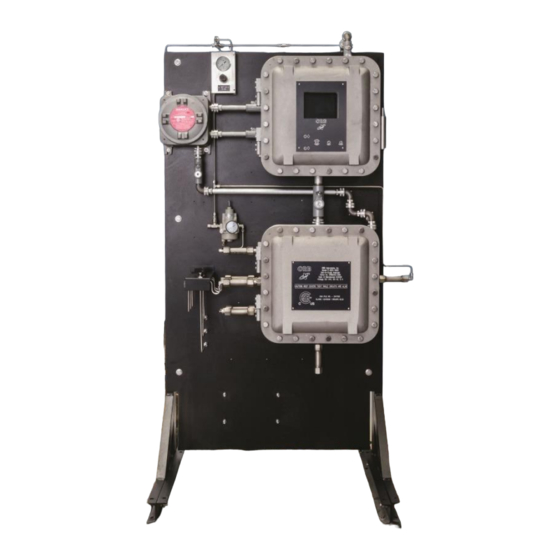
P-600 SIC Analyzer Manual 5 psi Air Air IN Maintenance Valves Filling Pumps and Ports Figure 1-3: Solvent Flow Schematic Component Identification Figure 1-4: Upper Control Enclosure Chapter I: Introduction... - Page 10 P-600 SIC Analyzer Manual Figure 1-5: Front View Chapter I: Introduction...
-
Page 11: Menu Structure
P-600 SIC Analyzer Manual Figure 1-6: Lower Measurement Enclosure Menu Structure Choices / Settings / Main Menu Submenu Items Comments Analyzer Status – – Online / Offline Alarm History – Reset Reset Alarms log Validation History – Reset Reset Validation log Req. - Page 12 P-600 SIC Analyzer Manual Choices / Settings / Main Menu Submenu Items Comments Service – Used to check operation of Injector Control stepper motor Used to set Analog Output 4-20 Control signals Information about Conductive measurement circuit System Read, Cell Clean and...
- Page 13 P-600 SIC Analyzer Manual Choices / Settings / Main Menu Submenu Items Comments Setup Alarm Settings Warning Alarms Warning alarms settings Stream 1 Low and High values for stream 1 Stream 2 Low and High values for stream 1 Critical Alarms Critical alarms settings Max.
- Page 14 P-600 SIC Analyzer Manual Choices / Settings / Main Menu Submenu Items Comments Setup System Settings Choice OFF / Alarm Warning / Alarm Critical / Maintenance / Stream 1 / Stream 2 / Come Read / In Validation / Valid.
- Page 15 P-600 SIC Analyzer Manual Choices / Settings / Main Menu Submenu Items Comments Setup Factory Setup – For factory use only Security – – Disable / Enable Chapter I: Introduction...
-
Page 16: Chapter Ii: Specifications
P-600 SIC Analyzer Manual Chapter II: Specifications Models P-600-1400 CSA/CUS Class I, Division1, Group B, C and D P-600-1500 ATEX II 2G Ex db IIB+H2 T6 Gb P-600-1600 IECEx II 2G Ex db IIB+H2 T6 Gb Performance Measurement Range 0 to 400 PTB 0 to 1140 mg/Liter (g/m³) -
Page 17: Signal Inputs/Outputs
P-600-1400: CSA/CUS Class I, Division1, Group B, C and D P-600-1500: ATEX II 2G Ex db IIB+H2 T6 Gb P-600-1600: IECEx II 2G Ex db IIB+H2 T6 Gb Due to Bartec Orb commitment to continual product improvement, specifications subject to change without notice. Chapter II: Specifications... -
Page 18: Chapter Iii: Installation And Startup
-20°C and 40°C (-4°F and 104°F). MOUNTING The P-600 Salt in Crude Analyzer is mounted on a free-standing rack housed. It should be located on a flat, vertical surface and isolated from intense vibration. Ample space should be provided on all sides of the analyzer for access to connections, solvent reservoirs, etc. - Page 19 P-600 SIC Analyzer Manual Figure 3-1: Dimensional Drawing Chapter III: Installation and Startup...
-
Page 20: Solvent Supply
P-600 SIC Analyzer Manual PRESSURE REG. Figure 3-2: Left Side View Solvent Supply Three stainless steel reservoirs are provided on the rear of the free-standing rack for the measurement and cleaning solvents (see Figure 3-4). These reservoirs will hold approximately 36 liters (9.5 gallons) each of liquid. - Page 21 P-600 SIC Analyzer Manual Figure 3-3: Right Side View BLEEDING THE SOLVENT LINES The lines connecting the solvent tanks to the manifold must be purged of air prior to Analyzer start up and when solvents are replaced or replenished. The manifold incorporates a 3-way valve with air purge tube for each line for this purpose.
-
Page 22: Atmospheric Drain
P-600 SIC Analyzer Manual Visual Indicators Figure 3-4: Rear View / Solvent Tanks Atmospheric Drain The Measurement enclosure incorporates an atmospheric drain that should be piped to collection vessel for the recovery of spent sample. This drain is located at the bottom of the enclosure. - Page 23 P-600 SIC Analyzer Manual The P-600 Salt in Crude Analyzer requires an independent 110-120 or 230-240VAC (±10%), 50/60Hz power supply. The system is jumper selectable 110-120/220-240VAC (±10%) 50/60 Hz, single phase, 5A. AC power connections are made through the Customer Connections box attached to the upper left of the top enclosure (see Figure 3-2).
- Page 24 The connections for control room signals are made in the either the Customer Connections Enclosure or the Upper Control Enclosure (see Figures 3-5 and 3-7). Analog Output One isolated 4-20mA output is standard on the P-600 Salt in Crude Analyzer. An optional second 4-20mA output may be provided (see Figure 3-5). Relay Output The Analyzer incorporates three SPDT relay contacts rated at 3A resistive load at 250VAC.
- Page 25 P-600 SIC Analyzer Manual Figure 3-7: Upper Control Enclosure Digital dry contacts inputs are as follows: • Customer Alarm — This connection is used to stop the analysis, put the Analyzer Offline and activate Alarm Critical and Alarm Warning relays;...
-
Page 26: Startup
NOTE: Although the Validation Request and Stream Select contacts may be present, these functions are only available on Analyzers which incorporate these options. Contact Bartec Orb for more details. Startup WARNING: All necessary safety permits should be obtained, and the area checked for flammable vapors prior to opening the Analyzer’s enclosure... - Page 27 P-600 SIC Analyzer Manual 10. Verify that the atmospheric drain is working. 11. You are now ready to run analysis using the factory default settings or program the instrument with your desired operational parameters (see Chapter IV: Programming). 12. Close and bolt the Upper Control Enclosure and Lower Measurement Enclosure doors.
-
Page 28: Menu Navigation
Chapter IV: Programming Menu Navigation The P-600 Salt in Crude Analyzer is programmed and controlled via a magnetic keypad on the front of the Upper Control Enclosure (see Figure 4-1). This eliminates the need for opening the enclosure to change operational settings. - Page 29 P-600 SIC Analyzer Manual ANALYZER STATUS This field indicates the current status of the Analyzer. Touch the up/down arrow keys to change the status. Window message will appear to confirm or decline your choice. ALARM HISTORY This menu item provides access to the Alarm History submenu, which lists conditions which have activated one or more of the Analyzer’s alarm functions.
-
Page 30: Setup Submenu
P-600 SIC Analyzer Manual SETUP This menu provides access to the Analyzer’s Setup submenus. It is accessed by touching the Enter key when this menu item is highlighted. SECURITY This indicates the current status of the security setting. When Disabled, the operator has access to all Analyzer menus and submenus. - Page 31 P-600 SIC Analyzer Manual 4-20mA Outputs The P-600 Salt in Crude Analyzer’s analog outputs (Channel 1 standard; Channel 2 optional) can be programmed to output various types of information, as well as the range of the analog signal and an offset.
-
Page 32: Alarm Settings
P-600 SIC Analyzer Manual NOTE: If Salt in Crude graphing is enabled, the graph is updated at the end of each measurement. Alarm Settings This submenu screen is used to program the Analyzer’s alarms. Use the Index key to move to the desired menu item. Use the Up/Down Arrow keys to change the displayed setting or value. -
Page 33: System Settings
P-600 SIC Analyzer Manual System Settings The System Settings submenu allows you to establish global operating parameters for the Analyzer. Use the Index key to move to the desired menu item. Use the Up/Down Arrow keys to change the displayed setting or value. - Page 34 P-600 SIC Analyzer Manual NOTE: The Power Reset button on the side of the Customer Connections enclosure must be pressed to re-initialize the Analyzer whenever power is disrupted, even if Standby is set to Off. Validation • Validation Expected Value — This is the expected value of the validation sample.
-
Page 35: Communications Setup
P-600 SIC Analyzer Manual Alarm Critical – This type of alarm indicates Analysis has stopped because one of the critical conditions has been detected. Maintenance – Activated when the number of measurement cycles has exceeded the Max Cycles setting. Stream 1 –... -
Page 36: State Table
P-600 SIC Analyzer Manual This configures the Analyzer’s Modbus output. • ID — This is the ID assigned to the Analyzer. • Mode — This allows you to select either Ethernet or serial Modbus communication. When Ethernet is selected, the appropriate IP, router, and network mask addresses must be assigned. -
Page 37: Calibration
P-600 SIC Analyzer Manual CAUTION: Any changes made will affect how the Analyzer performs a measurement. You should have a complete and thorough understanding of how the instrument performs measurements before making any changes to the State Table. Any of the following steps can be included in a salt in crude measurement cycle. Steps that are underlined are required. -
Page 38: Time/Date Setup
P-600 SIC Analyzer Manual Time/Date Setup The Time/Date Setup submenu is used to set the Analyzer’s internal calendar and clock. • Time Format — This menu item allows you to select either a 12- or 24-hour time format. Touch the Up/Down Arrow keys to change the displayed value. -
Page 39: Chapter V: Normal Operation
P-600 SIC Analyzer Manual Chapter V: Normal Operation In normal operation, the P-600 Salt in Crude Analyzer continuously measures salt content in crude oil. These measurements and other pertinent monitoring information are displayed on the Analyzer’s display in the Main Run screen. Measurement data are also output as analog and/or digital signals. Upon the application of power, the Analyzer runs a short initialization program and then displays either the Main Run screen or the Main Menu, depending on how the Standby mode has been set up (see Chapter IV). -
Page 40: Signal Outputs
Signal Outputs 4-20mA Analog Output The P-600 Salt in Crude Analyzer outputs an analog signal proportional to the last measured value. The range of the analog signal is user programmable (see Chapter IV: Programming). This signal is updated at the end of the measurement cycle. -
Page 41: Alarms
P-600 SIC Analyzer Manual Alarms When an alarm condition is detected, a message might be displayed in the Message Line of the current screen and/or relay will be activated (depending on the type of alarm and the user-programming of the alarm relays). -
Page 42: Solvent Supply
See Chapter IV: Programming. Taking the Analyzer Offline The P-600 Salt in Crude Analyzer may be taken offline either locally or remotely. Locally From the Main Menu, under Analysis Status, tap the Up or Down Arrow key with the magnetic pencil. When the message box appears, confirm your choice with Enter key to toggle the status to offline mode. -
Page 43: Validation
P-600 SIC Analyzer Manual Remotely The Analyzer may also be taken offline via an optional remote dry contact digital input closure (see Chapter III). The instrument will remain idle until the signal is removed. A message indicating that the instrument has been remotely idled is displayed on the Main Run screen. - Page 44 P-600 SIC Analyzer Manual software. It is assumed that the output terminals will be connected to energize externally located solenoid valves. Their function is as follows: • Following the validation request and completion of the current cycle, the “Validation” Relay will be activated during the entire validation protocol.
-
Page 45: Sample Streams
Loss of Power Restart In the event of a power loss, the P-600 Salt in Crude Analyzer will automatically begin monitoring when power is restored if the Standby mode (see Chapter IV) is set to OFF. If the Standby mode is set to ON, the Analyzer will have to be placed online manually by accessing the Main Menu and then setting Status to ON. -
Page 46: Internal Sample Leak
P-600 SIC Analyzer Manual Internal Sample Leak The Analyzer incorporates a sample leak detector (Figure 5-1) mounted on the bottom of the Measurement enclosure. Should an internal sample leak occur, accumulation of fluid in the bottom of the enclosure activates the leak detector and immediately removes power from the Measurement and Control enclosures. -
Page 47: Chapter Vi: Maintenance & Service
P-600 SIC Analyzer Manual Chapter VI: Maintenance & Service WARNING: Service should only be performed by qualified service personnel. Before performing any of the following procedures, disconnect unit from its electrical source. If electrical power is required, exercise extreme care as “LINE VOLTAGE” is present. - Page 48 P-600 SIC Analyzer Manual 4. Bleed off existing tank pressure. This is done via the valve on the right side of the tank assemblies (can vary) when facing the rear of the unit (see below). 5. If you have a filling station installed on your system, skip to step 6. Otherwise remove the plugs at the top of the tank and carefully pour your solvent into the tank.
-
Page 49: Service And Operational Checks
16. Bleed solvent lines per Chapter 3. 17. You are now ready to resume operations. Service and Operational Checks The P-600 Salt in Crude Analyzer incorporates a special Service screen from which the operator can perform a variety of verification and diagnostic functions, including: •... - Page 50 P-600 SIC Analyzer Manual Target – set point temperature for the measurement cell. Can be changed for testing. PID Control – automatic cell heater control (ON / OFF). • Output Control Sample Valve – allows you to activate (ON) and deactivate (OFF) the sample loop;...
- Page 51 P-600 SIC Analyzer Manual Figure 6-1: Internal Solenoid Valves • 4-20 Control 4-20 Out 1 – this menu item allows you to output an analog signal via the Analyzer’s first 4-20 mA output channel. Use the up/down arrow keys to increase/decrease the output value;...
-
Page 52: Calibration
The Analyzer’s software will use that table to perform quadratic regression in order to find the formula for calculating Salt in Crude concentration. NOTE: Bartec Orb recommends a minimum of four calibration samples (data points) for calibration table. -
Page 53: Troubleshooting
P-600 SIC Analyzer Manual 3. The other data point should be outside the expected range and can be obtained through linear extrapolation (most calibration curves seen are linear or near linear). Example (0-75 PTB calibration): Take conductance for “0” Salt in Crude concentration from the current table or Factory QIR. - Page 54 P-600 SIC Analyzer Manual Problem / Symptom Cause Corrective Action SIC out of range Detected SIC value is outside the Allow unit to run additional (warning alarm expected range of the Analyzer cycles. Process fluctuations or activated) changeovers can cause SiC...
-
Page 55: Assembly Drawings
P-600 SIC Analyzer Manual Assembly Drawings MEASUREMT ENCLOSURE Item No. Quantity Part Number Description 700524 Exp Proof Analyzer Enclosure Back Plate 700792 Detection Cell Back Plate 700796 Drain Solenoid Bracket 701389 Measurement Assembly 650019 4-way Air Solenoid Valve 1/8” Quik-Connect Elbow 650218 1/8”... - Page 56 P-600 SIC Analyzer Manual STEPPER MOTOR ASSEMBLY Item No. Quantity Part Number Description 702654 SIC Stepper Motor Assembly 651139 3 Way Solenoid 700100 Optical PCB 640001 Stepper Motor 702213 Syringe Adapter 702202 Syringe Guide 690024 5 mL Syringe Chapter VI: Maintenance & Service...
- Page 57 P-600 SIC Analyzer Manual UPPER CONTROL ENCLOSURE Item No. Part Number Description 701910 Mounting Plate for Main PCB 798115 Main Power Distribution PCB 620038 Power Supply (+24 VDC) 620037 Power Supply (+5, +/- 12VDC) 701911 Fish Paper for Main PCB...
- Page 58 P-600 SIC Analyzer Manual CONTROL ENCLOSURE DOOR Item No. Part Number Description 701321 Keypad Overlay 798030 Magnetic Keypad 620600 Backlight Driver PCB 700348 Magnetic Pencil Holder 700701 Magnetic Pencil Assembly 798063 Display Controller PCB 620583 Graphics Display 702972 Display Bracket...
-
Page 59: Chapter Vii: Spare Parts
P-600 SIC Analyzer Manual Chapter VII: Spare Parts Spare Parts Kits Description Part Number 1-YEAR PARTS KIT ....................... 700641 3-way Solenoid (5 each)................651139 4-way Solenoid (1 each)................650019 Drain Solenoid (1 each)................651006 5 mL Syringe (2 each) ................690024 Salt-in-Crude Tubing Kit (1 each) .............. -
Page 60: Replacement Parts
P-600 SIC Analyzer Manual Replacement Parts Description Recommended Quantity Part Number Fuse (250VAC, 15A) ..........1 .............. 600051 Fuse (250VAC, 10A) ..........2 .............. 600052 Power Supply (+5, +/- 12VDC)......1 .............. 620037 Syringe Stepper Motor ......... 1 .............. 640001 3-way Solenoid .............
Need help?
Do you have a question about the P-600 and is the answer not in the manual?
Questions and answers