
Subscribe to Our Youtube Channel
Related Manuals for Bartec ORB P-800LT


Summary of Contents for Bartec ORB P-800LT
- Page 1 ATEX Zone 1 II B + T6 CSA/CUS Class 1 Div 1 Group C + D Process Analyzer User Manual P-800LT FREEZE POINT ANALYZER, LOW TEMP...
-
Page 2: Table Of Contents
11-07-2013 OREWORD OREWORD Table of Contents............................i Warranty................................ v NTRODUCTION ECTION Analyzer Overview ............................. 1-1 Principle of Operation..........................1-1 Component Identification ........................... 1-4 Front View............................1-4 Control Enclosure ..........................1-6 Measurement Enclosure........................1-7 Menu Structure ............................ 1-8 PECIFICATIONS ECTION Models................................ 2-1 Performance............................... - Page 3 11-07-2013 – S ROGRAMMING ECTION Main Run Screen ............................4-1 Menu Navigation ............................4-1 Advance Screen Key ........................... 4-2 Index Key............................. 4-2 Enter Key ............................. 4-2 Up/Down Arrow Keys .......................... 4-2 Main Menu..............................4-2 Analyzer Status............................ 4-2 Alarm History ............................4-2 Validation .............................
- Page 4 11-07-2013 FP Threshold ........................4-11 Detect ...........................4-11 Relay Setup..........................4-11 State Table Setup ..........................4-12 Time/Date Setup..........................4-14 Factory Setup ............................4-14 – S ORMAL PERATION ECTION Main Run Screen ............................5-1 Freeze Point Analysis Results......................5-1 Date & Time............................5-1 Graphical Data Display........................5-1 Operational Status ..........................
- Page 5 11-07-2013 Az90 Volts............................6-3 Troubleshooting ............................6-4 Assembly Drawings............................ 6-5 Measurement Enclosure........................6-5 Control Enclosure ..........................6-6 Control Enclosure Door ........................6-7 – S PARE AND EPLACEMENT ARTS ECTION Spare Parts Kits ............................7-1 Replacement Parts............................. 7-2 P-800LT Freeze Point Analyzer Foreword...
-
Page 6: Warranty
11-07-2013 ARRANTY OLICY Orb Instruments warrants its products to the original purchaser against any defects that are due to faulty material or workmanship for a period of one year from date of shipment unless otherwise noted in the product manual. In the event that a defect is discovered during the warranty period, Orb Instruments agrees that, at its option, it will repair or replace the defective product or refund the purchase price, excluding original shipping and handling charges. -
Page 7: Introduction Section Analyzer Overview
11-07-2013 NTRODUCTION ECTION NALYZER VERVIEW The ORB Instruments’ Model P-800LT Freeze Point Analyzer is an on-line instrument designed for the continuous measurement of freeze point in hydrocarbon refining processes. Extremely rugged and simple to operate, the compact P-800LT Freeze Point Analyzer combines rapid analysis, exceptional measurement accuracy, and unmatched operational dependability to deliver highly reliable and repeatable freeze point determinations day in, day out, month after month. - Page 8 11-07-2013 Figure 1-1a: Flow Schematic (Analyzers with a Water-Cooled Cryocooler) P-800LT Freeze Point Analyzer Introduction...
- Page 9 11-07-2013 Figure 1-1b: Flow Schematic (Analyzers with an Air-Cooled Cryocooler) A typical measurement cycle takes less than ten minutes and is performed as follows: The sample solenoid opens and fresh sample is flushed through the detection cell to warm and dislodge any wax crystals which may have remained on the detection cell windows from the previous measurement.
-
Page 10: Component Identification
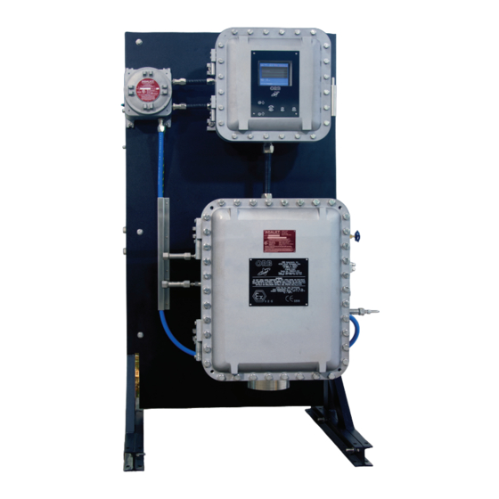
11-07-2013 OMPONENT DENTIFICATION RONT Control Enclosure Customer Connections Enclosure Air In Pressure Regulator Measurement Enclosure Measurement Enclosure Drain Figure 1-2a: Front View (Analyzers with a Water-Cooled Cryocooler) P-800LT Freeze Point Analyzer Introduction... - Page 11 11-07-2013 Customer Control Connections Enclosure Enclosure Air In Pressure Regulator Measurement Enclosure Measurement Enclosure Drain Figure 1-2b: Front View (Analyzers with an Air-Cooled Cryocooler) P-800LT Freeze Point Analyzer Introduction...
-
Page 12: Control Enclosure
11-07-2013 ONTROL NCLOSURE Main Control Digital Inputs Fuses Power Switch Figure 1-3: Control Enclosure P-800LT Freeze Point Analyzer Introduction... -
Page 13: Measurement Enclosure
11-07-2013 EASUREMENT NCLOSURE Cryocooler Drive Detection Cell Air- or Water-Cooled Cryocooler Leak Detector Figure 1-4: Measurement Enclosure P-800LT Freeze Point Analyzer Introduction... -
Page 14: Menu Structure
11-07-2013 TRUCTURE Sub- Main Menu Items Choices / Settings / Comments Menu Analyzer — — On Line / Off Line Status Alarm — — Display only History Validation — Validation Digital / Auto / Manual / Off Sys Temperatures For future use Sample Display only –... - Page 15 11-07-2013 Sub- Main Menu Items Choices / Settings / Comments Menu 4-20 Out 1 Output CP1 / CP2 / Cell Temp / Sig 0 / Sig 90 / Validation 4 mA Value = 4 mA signal 20 mA Value = 20 mA signal Offset value Offset 4-20 Out 2...
- Page 16 11-07-2013 Screen Settings Intensity / Screen Saver Flush Heat % power applied to heater during flush step Cell Heat % power applied to heater during cell heating CP Cool % power applied to the cooling module Sig 90 IR Sensor sensitivity (Detect = Sig90 only) Mode Settings Standby Mode On / Off...
-
Page 17: Models
11-07-2013 PECIFICATIONS ECTION ODELS P-800LT-1400 For NEC Class I, Division 1, Group C and D areas. P-800LT-1500 For ATEX Zone I, II B + H2 T4 areas. ERFORMANCE Measurement Range Minimum: -100°C (-148°F) Maximum: +25°C (+77°F) Repeatability ±0.5°C (1.0°F) Reproducibility Meets or exceeds ASTM Method D-2386 or IP-16 Resolution ±0.25°C (0.5°F) -
Page 18: Signal Inputs/Outputs
11-07-2013 IGNAL NPUTS UTPUTS Analog Output One isolated 4-20 mA output standard; Optional second isolated 4-20 mA output available. Signal output information is programmable. Serial Communication Bi-directional RS232 (RS485 optional) Relay Output Three SPDT failsafe relay contacts rated at 3A resistive load at 250 VAC. -
Page 19: Installation And Startup Section
11-07-2013 NSTALLATION AND TARTUP ECTION WARNING: Installation or operation of this Analyzer outside of the parameters indicated in the Specifications could result in personal injury or damage to the Analyzer. Installation, operation, and maintenance should performed only by fully qualified personnel. - Page 20 11-07-2013 Figure 3-1a: Dimensional Drawing (Analyzers with a Water-Cooled Cryocooler) P-800LT Freeze Point Analyzer Installation and Startup...
- Page 21 11-07-2013 Figure 3-1b: Dimensional Drawing (Analyzers with an Air-Cooled Cryocooler) P-800LT Freeze Point Analyzer Installation and Startup...
-
Page 22: Piping
11-07-2013 IPING The P-800LT Freeze Point Analyzer incorporates fittings for connecting process sample, purge gas lines, and plant cooling water. There is also a fitting for connecting a validation sample line if this option has been installed on the Analyzer. These fittings are located on the sides of the instrument. See Figures 3-2 and 3-3. - Page 23 11-07-2013 Control Enclosure Electrical Power In Power Reset Button Customer Connections Enclosure Instrument Air In Measurement Enclosure Process Sample Out Optional Detection Cell Purge Gas In Process Sample In Measurement Enclosure Drain Figure 3-2b: Left Side View (Analyzers with an Air-Cooled Cryocooler) P-800LT Freeze Point Analyzer Installation and Startup...
- Page 24 11-07-2013 Customer Connections Control Enclosure Main Power Switch Measurement Enclosure Measurement Enclosure Drain Figure 3-3a: Right Side View (Analyzers with a Water-Cooled Cryocooler) P-800LT Freeze Point Analyzer Installation and Startup...
- Page 25 11-07-2013 Customer Connections Control Enclosure Main Power Switch Measurement Enclosure Measurement Enclosure Drain Figure 3-3b: Right Side View (Analyzers with an Air-Cooled Cryocooler) P-800LT Freeze Point Analyzer Installation and Startup...
-
Page 26: Process Sample Lines
11-07-2013 ROCESS AMPLE INES NOTE: It is the user’s responsibility to assure that a representative sample, free of moisture and particulate matter, is presented to the instrument for analysis. ORB Instruments can assist in specifying sample conditioning requirements and the selection/development of an appropriate sample conditioning system. -
Page 27: Wiring
11-07-2013 IRING LECTRICAL OWER WARNING: This Analyzer is designed to meet the requirements of either the National Electrical Code (NEC) for installation in Class I, Division 1, Group C and D or European ATEX Zone 1, Group IIB hazardous areas. It is the user’s responsibility to complete the electrical connections and comply with all pertinent codes. -
Page 28: Control Room Signals
11-07-2013 The P-800LT-1500 Freeze Point Analyzer has internal and external grounding harnesses that tie all enclosures and power distribution together to a grounding lug mounted to the Analyzer frame leg. The ® grounding wire is 10 gauge with a green/yellow spiral Teflon insulation and a 36 x 26 strand. -
Page 29: Modbus
11-07-2013 ModBus ModBus is available as a factory-installed option which utilizes either the Analyzer’s TCP/IP connection for ModBus or its serial ModBus connection. This connection is made in the Control Enclosure (Figure 3- 6). Consult ORB Instruments for more information. Digital Inputs The Analyzer incorporates four sets of voltage dry contacts that allow the control room to remotely activate selected functions. -
Page 30: Startup
11-07-2013 NOTE: Although the Validation Request and Stream Select contacts may be present, these functions are only available on Analyzer’s which incorporate these options. TARTUP 1. Start flow of process sample to the Analyzer and verify that the flow rate is regulated at 1.4 to 10 bar (20 to 100 psi). - Page 31 11-07-2013 H. Turn NIR Source OFF. Adjust the value of the Stream 1 analog output signal (4-20 Control) to 4 mA and verify that the proper signal was received by the control room. J. Repeat the loop check for Stream 1 at values of 12 mA and 20 mA. K.
- Page 32 11-07-2013 [THIS PAGE INTENTIONALLY BLANK] P-800LT Freeze Point Analyzer 3-14 Installation and Startup...
-
Page 33: Programming Section
11-07-2013 ROGRAMMING ECTION CREEN When the P-800LT Freeze Point Analyzer is powered up, a short initialization program runs and either the Main Run Screen or Main Menu will appear. The Main Run Screen appears if the unit is programmed to power up in On-Line mode;... -
Page 34: Advance Screen Key
11-07-2013 To enter or exit the analysis mode, move to a new menu or within menu items, change a displayed value, the operator simply touches a magnet to the designated location on the keypad. These locations function as follows: Advance Screen Key — When the Main Run screen displayed, touching this key brings up the Main Menu. -
Page 35: Validation
11-07-2013 ALIDATION This menu item provides access to the Validation sub-menu. It allows the operator to determine how validation measurements will be initiated. Touch the Enter key to access this sub-menu and then touch the Up/Down Arrow keys to toggle through the available choices. Digital —... -
Page 36: Setup Sub-Menu
11-07-2013 ETUP MENU The Setup sub-menu is used to establish the Analyzer’s various operating parameters. Use the Index key to advance to the desired (highlighted) menu selection. Touch the Enter key to access the selected sub-menu. UTPUT ETTINGS This menu item is used to program the Analyzer’s analog output and digital output parameters. It is also used to establish how freeze point measurement information will be displayed on the Main Run screen. -
Page 37: Out 1 / 4-20 Out 2
11-07-2013 4-20 Out 1 / 4-20 Out 2 — The P-800LT Freeze Point Analyzer’s analog outputs (one standard; second optional) can be programmed to output various types of information, as well as the range of the analog signal and an offset. Output —... - Page 38 11-07-2013 Low — This establishes the bottom of the trend graph’s temperature scale. This value should be set below the lowest expected Freeze point temperature. High — This establishes the top of the trend graph’s temperature scale. This value should be set above the highest expected Freeze point temperature.
-
Page 39: Fp History
11-07-2013 FP History — When this is selected, measurement data for the most recent 1000 detection cycles are displayed. CP corresponds to cloud point; FP corresponds to freeze point. Enabled/Disabled — Turns this the measurement history display ON and OFF. Low —... -
Page 40: Alarm Settings
11-07-2013 LARM ETTINGS This menu item is used to program the Analyzer’s alarm output. Use the Index key to advance to the desired menu item. Use the Up/Down Arrow keys to change the displayed setting or value. Alarm Range — These menu items are used to establish the temperature values at which the Analyzer’s freeze point temperature alarm will be activated. -
Page 41: Other Settings
11-07-2013 THER ETTINGS The Other Settings sub-menu allows you to establish global operating parameters for the Analyzer. Reload Defaults — This menu item is used to restore the Analyzer’s factory default settings. When accessed by touching the Enter key, the following message appears: “Are you sure? UP = Yes, DOWN = No”... - Page 42 11-07-2013 Customer Alarm — When enabled, the Analyzer’s system alarm relay will be activated whenever an external dry contact alarm signal is received. Analysis will stop and will have to be restarted from the front panel of the instrument. Remote Standby — When enabled, the Analyzer can be placed on-line or off-line via a control room signal.
-
Page 43: Customer Alarm
11-07-2013 FP Threshold — This is a sensitivity setting for freeze point detection. The higher the value, the more the optical signal will have to change before freeze point is detected. Detect — This setting determines which sensor is used to determine freeze point. It may be set for Sig0 or Sig90. -
Page 44: State Table Setup
11-07-2013 TATE ABLE ETUP This menu selection allows you to modify, add, or delete steps in the Freeze point measurement process. NOTE: Any changes made will affect how the Analyzer performs a Freeze point measurement. You should have a complete and thorough understanding of how the instrument performs Freeze point measurements before making any changes to the State Table. - Page 45 11-07-2013 Abort — This selection immediately stops the analysis and prevents the Analyzer from proceeding. It is intended as a troubleshooting tool only and should never be included as part of a normal Freeze point measurement cycle. Return — This should always be the last step in the State table. It tells the Analyzer to return to step 1. Factory Default State Table Step Time...
-
Page 46: Time/Date Setup
11-07-2013 ETUP The Date / Time Setting sub-menu is used to set the Analyzer’s internal calendar and clock. Time Format — This menu item allows you to select either a 12 or 24 hour time format. Touch the Up/Down Arrow keys to change the displayed value. Date Format —... -
Page 47: Normal Operation Section
11-07-2013 ORMAL PERATION ECTION The P-800LT Freeze Point Analyzer is an on-line process instrument designed for the continuous measurement of freeze point in hydrocarbon process streams. In normal operation, these measurements and other pertinent monitoring information are displayed on the Analyzer’s liquid crystal display. -
Page 48: Signal Outputs
11-07-2013 Operational Status — Identifies the status and state of various Analyzer components and systems. Sample — Status of the sample solenoid. Cell — The percent power being applied to the heater. Cooler — Status of the cryocooler. Stream — Identifies stream currently being analyzed (on Analyzers with the stream switching option). -
Page 49: Serial Output
11-07-2013 ERIAL UTPUT The Analyzer normally outputs an RS232 serial signal (RS485 output is available as a factory installed option). Data are output according to the following protocol: Baud Rate 19200 Parity No parity Start Bits Stop Bits Field Delimiter Comma End of Data Indicator <CR>... -
Page 50: Alarm Warning
11-07-2013 Type Alarm Messages and Conditions Analyzer State Alarm Warning Freeze point out of range Analysis continues Alarm Critical Freeze not detected Analysis stops Alarm Critical Temp. sensor failure Analysis stops Alarm Critical Temp. control failure Analysis stops Alarm Critical Optic failure Analysis stops Alarm Critical... -
Page 51: Alarms History
11-07-2013 LARMS ISTORY Operational alarms are logged and may be accessed via the Alarms History sub-menu. To access this sub-menu, go to the Main Menu, select Alarms History, and touch Enter. The Alarms History screen will appear. To clear the alarm history, touch the Enter key when Reset is highlighted. AKING THE NALYZER The P-800LT Freeze Point Analyzer may be taken off-line either locally from the front panel of the... -
Page 52: Switching Sample Streams
11-07-2013 NOTE: When a validation measurement is being performed, the 4-20 mA signal is held at the last measured Freeze point value. The signal is not updated until a new Freeze point measurement is performed. The measured Freeze point value of the validation sample is NOT output as an analog signal. -
Page 53: Routine Maintenance & Service - Section
11-07-2013 & S OUTINE AINTENANCE ERVICE ECTION WARNING: Service should only be performed by qualified service personnel. Before performing any of the following procedures, disconnect unit from its electrical source. If electrical power is required, exercise extreme care as “LINE VOLTAGE”... -
Page 54: System Temperatures
11-07-2013 System Temperatures — This is an informational display only. T1 — For future use. Sample — This is the temperature inside the sample cell. Sensor — For future use. Output Control — The operation of the Analyzer’s various solenoids can be checked via these menu items. -
Page 55: Optical System
11-07-2013 Optical System — The operation of the Analyzer’s optical system can be checked via these menu items. NIR Power — This controls the strength of the NIR light source and allows you to check the operation of the optical sensors. The signal 0 and signal 90 values should increase/decrease in conjunction with the changes in the NIR power. -
Page 56: Troubleshooting
11-07-2013 ROUBLESHOOTING Problem / Symptom Cause Corrective Action Freeze point out of Detected freeze point value is Allow unit to run additional cycles. range outside the expected range of the Process fluctuations or changeovers Analyzer can cause out of range alarms due to different sample characteristics. -
Page 57: Assembly Drawings
11-07-2013 SSEMBLY RAWINGS EASUREMENT NCLOSURE P-800LT Freeze Point Analyzer Routine Maintenance & Service... -
Page 58: Control Enclosure
11-07-2013 ONTROL NCLOSURE P-800LT Freeze Point Analyzer Routine Maintenance & Service... -
Page 59: Control Enclosure Door
11-07-2013 ONTROL NCLOSURE P-800LT Freeze Point Analyzer Routine Maintenance & Service... - Page 60 11-07-2013 [THIS PAGE INTENTIONALLY BLANK] P-800LT Freeze Point Analyzer Routine Maintenance & Service...
-
Page 61: Spare And Replacement Parts Section
11-07-2013 PARE AND EPLACEMENT ARTS ECTION PARE ARTS Description Part Number ....................... 700506 ARTS Cartridge heater, 2 each Optical window O-ring, 2 each Type J thermocouple, 1 each ....................... 700507 ARTS 3-way solenoid, 1 each Cartridge heater, 4 each Optical window O-ring, 4 each Type J thermocouple, 1 each P-800LT Freeze Point Analyzer Spare and Replacement Parts... -
Page 62: Replacement Parts
11-07-2013 EPLACEMENT ARTS Description Part Number Cartridge Heater, 1 each ......................620078 Fuse (250 VAC, 2 A) / 230 VAC Systems, 1 each ............... 620035 Fuse (250 VAC, 5 A) / 115 VAC Systems, 1 each ............... 620036 Power Supply (+5, ±12 VDC), 1 each ..................620037 Power Supply (+24 VDC), 1 each ....................
Need help?
Do you have a question about the ORB P-800LT and is the answer not in the manual?
Questions and answers