Table of Contents
Advertisement
Quick Links
Advertisement
Table of Contents

Related Manuals for Bartec HYGROPHIL H 4230-10 A Series


Summary of Contents for Bartec HYGROPHIL H 4230-10 A Series
- Page 1 ® HYGROPHIL H 4230-10 Serie A Operating Instructions Software Version 2.00 BA 030520 BARTEC BENKE GmbH Schulstraße 30 D-94239 Gotteszell Telefon +49(0)9929)-301-0 Telefax +49(0)9929)-301-112 E-Mail: gotteszell@bartec-benke.de Internet: www.bartec-benke.de...
-
Page 3: Table Of Contents
Contents C - 1 Table of Contents System description ......................... 1 Task and fields of use ....................1 Measurement principle ....................2 Structure of the humidity measurement system ............2 1.3.1 Measuring chamber ...................... 4 1.3.2 Ejector ........................... 5 1.3.3 Hose pump ........................ - Page 4 Contents C - 2 Installation with enclosure type 4230-119 ..............51 3.9.1 Mounting the gas sampling hose ................54 3.9.2 Panel heater ....................... 55 3.9.3 Heated hose incl. change-over gate, Type 4230-112 ..........57 Operation ............................58 Start-up ........................58 Operating mode......................
- Page 5 Contents C - 3 8.3.2 Measured value channel ...................104 8.3.3 Arithmetic value channel ...................105 8.3.4 Output channel......................106 8.3.5 1-channel parameters ....................108 8.3.6 2-channel parameters ....................110 Examples ........................114 8.4.1 Reading from HYGROPHIL H ..................114 8.4.2 Writing to HYGROPHIL H ..................115 Operating Instructions HYGROPHIL® H 4230-10 Serie A BA 030520...
- Page 6 New added Copyright © 2018 by All rights reserved. Subject to change without prior notice. BARTEC BENKE No part of this document may be reproduced, processed or distributed in any form or by any means without the prior written permission of Schulstraße 30...
-
Page 7: System Description
System description System description Task and fields of use Task ® HYGROPHIL H 4230 is a measuring system for determining the amount of water vapour in air and other gases. In many processes, monitoring and controlling gas humidity is a must if you want to achieve a consistently high product quality, use energy efficiently and adhere to the regulations regarding emission limits. -
Page 8: Measurement Principle
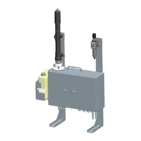
System description Measurement principle ® HYGROPHIL H 4230 works in accordance with the principle of psychrometric gas humidity measurement, measuring the difference in temperature between two measurement sensors. The difference in temperature results from the fact that one of the two temperature sensors is moistened. - Page 9 System description Gas sampling hose Connecting cable for hose heating Water container Electronics enclosure Measuring chamber enclosure Compressed air maintenance unit Operating Instructions HYGROPHIL® H 4230-10 Serie A BA 030520...
-
Page 10: Measuring Chamber
System description 1.3.1 Measuring chamber The venturi system and the water cylinder with the humidity sensors are accommodated in the measuring chamber. To begin with, the air to be measured flows through a venturi nozzle, in which the gas flow rate is determined by measuring the difference in pressure. -
Page 11: Ejector
System description 1.3.2 Ejector The lower section of the measuring chamber contains the ejector, an air jet pump that pumps the measurement air through the measuring chamber by means of compressed air. Negative pressure of up to -200 hPa is allowed at the extraction point. -
Page 12: Controls And Displays
System description 1.3.6 Controls and displays When the enclosure door on the right is opened, the operator panel becomes accessible, together with its display, signal lamps and operating keys. Display Keys Signal lamps 1.3.6.1 Keys The measurement variables are displayed by simply pressing a key. The keys that can be pressed to display the measurement variables are labelled appropriately. - Page 13 System description Display of the dry temperature of the incoming gas (corresponds to the gas sampling hose temperature) Display of the humid temperature of the incoming gas Display of the dew-point temperature of the gas to be measured Display of the volumetric water vapour content VOL% Display of the current partial water vapour pressure of the gas to be measured...
- Page 14 System description Display of the temperature value of T1 (only if T1 is activated) external external Backlighting ON/OFF Display of the proportional valve regulation ratio Display of the internal temperature (T Standby (the pump speed is decreased by a factor of 10, while the setpoint value for the differential pressure is fixed) Key for changing the slave address and displaying the baud rate Test function for analogue outputs...
-
Page 15: Signal Lamps
System description 1.3.6.2 Signal lamps For the purpose of signalling various operating states, the panel contains six fields with symbols and a signal lamp for each. The heating (gas sampling hose) is switched on (red) The water pump is in operation (red) The proportional valve is opening (red) -
Page 16: Temperature Sensors
System description 1.3.8 Temperature sensors The internal temperature sensor, T , is built into the enclosure as a fixed internal element. It is used for compensating the humid temperature. For measuring temperature-dependent humidity variables (such as relative humidity (RH) or enthalpy (h)), you have the option of installing an external temperature sensor (T1 ). -
Page 17: Technical Data
System description Technical data Humidity measurement Measurement principle Psychrometric gas humidity measurement in line with the impact jet method Transducer PT 100/ 4-conductor in accordance with DIN IEC 751 0.01% Computational accuracy Computing time Approx. 2s (for a sudden change in VOL% from 0 to 40%) Settling time = <170s (bei VOL%-Sprung von 0 auf 40%) Air/gas flow rate... - Page 18 System description Mechanical data Enclosure Stainless steel enclosure; protection rating IP64 in accordance with DIN 40050 Dimensions 450410150 mm (without mount) Assembly drill holes 347x330 mm, 47x13mm (M6) Weight Approx. 12.5 kg Connections Electrical connection Screw terminals 0.5-1.5 mm ; cable feed via M 16x1.5 cable gland Compressed air supply Plug nipple NW 7 Gas sampling hose connection...
-
Page 19: Details When Ordering
System description Details when ordering 1.5.1 Basic equipment H Type 4230-10 HYGROPHIL Corrosion-proof, 115/230 V a.c. Scope of delivery: HYGROPHIL-H in accordance with order number; 1 litre of surfactant Order number: 202728 1.5.2 Accessories Gas sampling hose, Type 4230-100 Flexible, water-resistant gas sampling hose for feeding measurement gas without condensate (max. input temperature 200 °C);... - Page 20 System description Measurement gas tube, Type 4200-06 Connection type: Universal conical nipple G 3/8“ DKR DIN3863 PT 100 Length Order number (230 V) 13,0 m U7521113420006 15,0 m U7521115420006 19,0 m 202222 20,0 m U7521120420006 23,0 m U7521123420006 24,0 m 320764 26,0 m 220718...
- Page 21 System description Measurement gas tube self-regulating, Type 4230-128 Length Order number (230 V) 4,0 m 367556 8,0 m 348425 Distribution box heated, AC 230 V, with ball valve, Type 4230-135 Compression fitting PTFE DKR-3/8“ (connection adapter for for pipe diameter 8 mm measurement gas tube) Order number : 376237...
- Page 22 System description Water container 2l, without holding, Type 4230-300 Order number : 202156 Water container 11l, with holding, Type 4230-102 Order number : 216420 Water container 11l without holding, Type 4230-133 Order number: 367964 Operating Instructions HYGROPHIL® H 4230-10 Serie A BA 030520...
- Page 23 System description Water sensor external, Type 4230-103 For monitoring the fill level in the water storage tank Order number: 216424 Adapter for gas sampling hose, stainless steel 1.4301 Adapter for gas sampling hose Hastelloy Type 4230-00-044 Type 4230-00-068 (DKR-3/8“ to NPT-1/4“) (DKR-3/8“...
- Page 24 System description Adapter 6HMK4SS Straight connector (DKR-3/8“, stainless steel) Order number: 320763 Standard filter, with flange DN65/PN6 and adapter for gas sampling hose, Type 4220-100 including sinter filter cartridge 150-µm CrNi Steel 1.4404 Order number: 208686 Sinter filter cartridge Type 4220-106 for Standard filter 150 µm, CrNi-Steel 1.4404 Order number:...
- Page 25 System description Filter flange , with adapter for gas sampling hose, Type 4230-125 DN65/PN6 Filter flange Order number: 296346 Gas sampling hose adapter for Filter G3“ Type 4230-00-089 Order number: 387933 Filter G3/4“ Order numbers Filter Replacement hose V20-6; 500 °C max.; 520 x 60 mm² 319545 V20-T;...
- Page 26 System description Gas sampling probe Type Order number (230 V) Order number (115 V) SP 2000-HF-GF 150 214334 292337 SP 2000HF/HC (Hastelloy) 292899 Glass fiber filter Type GF 150 for gas sampling probe SP 2000 / SP 2200 0,1 µm Order number: 220232 Welding flange DN 65PN6 with Clamp connection, Type 4230-130...
- Page 27 System description Sampling probe , 230V, 0 - 180 °C, rinsable Type SP2200-HF/I/BB Accessories: - Hex screws M 12x60 - Fitting washers and nuts - sealing Ø 160/68 mm - instructions Order number: 279032 Sampling probe , 230V, with solenoid valve island Type SP2200-HF/C/I/BB Order number: 365577...
- Page 28 System description Adapter for gas sampling hose 4220 to 4230, Type 4230-101 Order number: 216421 Nut for gas sampling hose, Type 4230-00-042 Order number: 202388 Stand holder, Type 4220-35 Order number: U 3401422035 Connection set for mobile measuring system type 4230-136 Includes: Compressed air hose with air connection 2,5m Rubber cable with SCHUKO solid rubber plug...
- Page 29 System description Compressed air maintenance unit, Type 4220-30 With compressed air regulator and filter Order number: U3401422030 Enclosure Type 4230-119 (Ex Zone 22) View without door Order number: 295991 Operating Instructions HYGROPHIL® H 4230-10 Serie A BA 030520...
- Page 30 System description Enclosure, Type 4230-127 without heating (Ex Zone 22) View without door Order number: 321358 Enclosure with gas sampling hose passage, Type 4230-129 Order number: 352826 Operating Instructions HYGROPHIL® H 4230-10 Serie A BA 030520...
- Page 31 System description Flange carrying, Type 4230-126 Order number: 312707 Assembly stand Type 4230-120 Order number: 300545 Operating Instructions HYGROPHIL® H 4230-10 Serie A BA 030520...
-
Page 32: Spare Parts
System description 1.5.3 Spare parts Tube pump cartridge, Type 4230-104 Order number: 216422 Measuring chamber with ejector, Type 4230-309 Serie A Without probes Order number: 423269 Water sensor, Type 4230-302 For monitoring the fill level in the measuring cell Order number: 202823 Pump motor, Type 4230-303 Order number:... - Page 33 System description Probe TT, Type 4230-304 Order number: 202411 Probe HT, Type 4230-305 Order number: 202410 Proportional valve, Type 4230-308 Order number: 202781 Display-/PROFIBUS board, Type 4230-122 Order number: 301656 Cover Plate with Keyboard Foil, Type 4230-121 The cover Plate is used in combination with the Display/PROFIBUS board type 4230-122.
- Page 34 System description Electronics board with power supply unit, Type 4230-400 Order number: 202412 Operating Instructions HYGROPHIL® H 4230-10 Serie A BA 030520...
-
Page 35: Individual Parts For Measuring Chamber
System description 1.5.4 Individual parts for measuring chamber Level indicator incl. gasket Type 4230-106 Order number: 232482 Water connection nipple for measuring cell Measuring cell completely, with ceramic ring Type 4230-117 (without water connection nipple) Type 4230-115 Order number: 278353 Order number: 278350 Special model... -
Page 36: Consumables
System description Inlet strainer incl. gasket Type 4230-110 Escape ejector chart no. 4230-00-032 Order number: 232458 Order number: 202706 Escape ejector Nut M5 chart no. 4230-00-054 for measuring chamber or cap fastener (2x3 pc per meas. chamber necessary) Order number: 222563 Order number: 202370... -
Page 37: Safety Precautions
Equipment-specific instructions ● The equipment must be installed and maintained by qualified technical personnel. ● Make sure that the data and operating conditions specified by BARTEC are observed. ● HYGROPHIL ® H 4230 is not suitable for measuring humidity in explosive mixtures of gas for which there are special safety regulations. -
Page 38: Installation Location
Safety precautions Installation location ● When installing the equipment, make sure that you observe the permissible climatic and temperature conditions in line with the technical data. ● If exceptional conditions exist at the installation location, suitable measures must be taken to protect the equipment. Please look at the accessories we offer with respect to this. -
Page 39: Operating The Equipment
BARTEC BENKE GmbH and its vicarious agents only assume liability in the case of deliberate acts or gross negligence. The extent of liability in such a case is limited to the value of the order placed with BARTEC BENKE GmbH. -
Page 40: Installation
Installation Installation ® Depending on the local circumstances and purpose of use, HYGROPHIL H 4230 can be installed as either a stationary unit (wall mounting) or a mobile unit. The entire installation must be carried out by a specialist, taking into account and observing the regulations stipulated in DIN/VDE 100 and the relevant national provisions for setting up power installations rated for up to 1000 volts. -
Page 41: Wall Mounting
Installation Wall mounting ● Select an installation location and drill the four mounting holes in line with the specifications in the diagram. ● Fix four screws in the holes. ● Attach the two fixation bars to the rear of the device. Ø... -
Page 42: Mobile Use
Installation Mobile use If the equipment is not to be installed for stationary use, you can fix it to the stand holder type 4220-35 (see section 1.5.2 Accessories). ● Place the unit on its front side. ● Unscrew the two mounting struts from the rear panel of the equipment. ●... -
Page 43: Connection Instructions
Installation Connection instructions 3.3.1 Assignment of terminals External external Warning Error water Heating OUT 1 OUT 2 Mains PROFIBUS relay relay detector hose – + – + – +5V A B 0V L N PE L N PE 3.3.2 Mains connection ●... -
Page 44: Temperature Sensors
Installation 3.3.3 Temperature sensors ● Only PT 100 resistance sensors are suitable as sensors (electric resistance 100 at 0 °C). ● Use a 4-strand shielded cable for the connection. ● Connect the shield on just one side of the terminals provided in order to avoid earth currents on the measuring unit. -
Page 45: Profibus
Installation 3.3.6 PROFIBUS ● Run the PROFIBUS cable through the two cable glands on the left. ● Connect the PROFIBUS cable to terminals 2 (PROFIBUS A) and 3 (PROFIBUS B). Jumper 1 Jumper 2 PROFIBUS A PROFIBUS B Shield Attention: If the unit is the last user in the PROFIBUS, the two jumpers must be closed. -
Page 46: Mounting The Gas Sampling Hose
Installation Mounting the gas sampling hose In order for the HYGROPHIL unit to be operated, it is vital that the gas sampling hose is mounted precisely. You should therefore observe the following instructions. Attention: Before mounting the gas sampling hose, make sure that it is designed for the same voltage as the unit. - Page 47 Installation wrong right Avoid buckling and bending stress! Use saddles or rolls with appropriate diameter. Avoid compressing or stretching the hose. Use elbows at the connections. Avoid torsional movements during mounting. Make sure that the axes of the hose run parallel and that the hose is not twisted.
-
Page 48: Mounting Sequence
Installation 3.4.2 Mounting sequence ● Screw the M 48 plastic knurled nut to the gas sampling hose mounting nut on the unit (A/F 47). ● Push the gas sampling hose stub carefully into the opening on the top of the unit. ●... -
Page 49: Assembly Of Removal / Filter Flanges
Installation Assembly of removal / filter flanges Notes: The temperature of the flanges must be well above the maximum dew point temperature Check for tightness so that false air does not affect the measured value Operating Instructions HYGROPHIL® H 4230-10 Serie A BA 030520... -
Page 50: Compressed Air Connection
Installation Compressed air connection ® In order to operate HYGROPHIL H 4230 it is necessary to install a compressed air connection that delivers maximum 17.5 Nl/min at a pressure of 2...5 bar. The pressure required depends on the negative pressure in the system from which the measurement gas is extracted. - Page 51 Installation Operating Instructions HYGROPHIL® H 4230-10 Serie A BA 030520...
-
Page 52: Mounting Sequence
Installation 3.6.1 Mounting sequence ● Connect the compressed air supply to the compressed air connector stub on the measuring unit. If the available supply pressure amounts to 5 bar or more, the compressed air conditioner must always be used. Although the maintenance unit is designed for mounting on a wall, it can also be operated when lying unsecured on a table. -
Page 53: Setting The Ejector's Operating Pressure
Installation Setting the ejector’s operating pressure 3.6.2 The gas to be measured is extracted from the respective system using the ejector and pumped through the measuring unit. The ejector is operated with compressed air. The operating pressure of the compressed air must be set in line with the pressure at the extraction point. -
Page 54: Filling The Water Storage Tank
Note: In cases in which a particular type of impurity occurs, a detergent other than the one supplied may be more effective. If required, ask BARTEC for advice, specifying the type of impurity. A larger water storage tank is available as an optional accessory. The content of 11 litres is enough for an operating duration of around 3 weeks. -
Page 55: External Water Detector
Installation External water detector You can install an external water detector for the purpose of monitoring the level in the water tank. The water detector is available as an optional extra. Connecting cable Assembly adapter Mounting holes for bolting 3.8.1 Electrical connection ●... -
Page 56: Installation
Installation 3.8.2 Installation ● Use two M 3 bolts and nuts to fix the external water detector to the inner side of the mounting strap (front side of the tank attachment) with the sensor side facing the tank. ● Then put the tank back in. External water detector Operating Instructions HYGROPHIL®... -
Page 57: Installation With Enclosure Type 4230-119
Installation Installation with enclosure type 4230-119 Attention: The enclosure is provided for using the device in explosion protected area of zone 22 in conformity with EN 61241-10 in a temperature range of -20...+50 °C. Follow the safety instructions of the manufacturer of the enclosure and the panel heater. - Page 58 Installation Mounting dimensions Measurement gas tube Panel heater Compressed air regulator Thermostat Operating Instructions HYGROPHIL® H 4230-10 Serie A BA 030520...
- Page 59 Installation The connection for compressed air supply and the gas outlet nozzle are connected to the corresponding nozzles at the bottom of the enclosure. Panel heater Thermostat Gas outlet connection Compressed air supply Operating Instructions HYGROPHIL® H 4230-10 Serie A BA 030520...
-
Page 60: Mounting The Gas Sampling Hose
Installation 3.9.1 Mounting the gas sampling hose ● Thread the gas sampling hose from inside to outside of the enclosure. At the same time put the hose clip over the hose. Hose clip ● Install the gas sampling hose according to section 3.4.2. ●... -
Page 61: Panel Heater
Installation 3.9.2 Panel heater ● The panel heater must be separately wired (independent of the measuring device) Use the terminals 3, 5, 6 at the thermostat according to the connection diagram. Rated voltage: AC 230 V Heat output: 300 W Operating Instructions HYGROPHIL®... - Page 62 Installation ● All cables and wires must be installed in the lead-throughs as required for the protection category. ● Observe the national safety regulations when installing. ● Set the thermostat to 20 °C. Danger of explosion! Never open the door of the enclosure in a dusty atmosphere! The door of the enclosure must be closed during operating.
-
Page 63: Heated Hose Incl. Change-Over Gate, Type 4230-112
Installation 3.9.3 Heated hose incl. change-over gate, Type 4230-112 Terminal block Type 4230-134 Operating Instructions HYGROPHIL® H 4230-10 Serie A BA 030520... -
Page 64: Operation
Operation Operation Start-up ® Before starting up HYGROPHIL H 4230, please check again that the following conditions are met. 1. Power supply – The mains voltage must correspond to the operating voltage of ® HYGROPHIL H 4230 and all components (gas sampling hose, filter, accessories). -
Page 65: Changing The Slave Address
Operation Changing the slave address The default slave address is 100. If you wish to change the slave address, press the F6 key in operating mode. The baud rate is then displayed briefly (if the device is working connected to Baudrate the bus). -
Page 66: Programming
Programming Programming You can program HYGROPHIL 4230 to prepare it for use in your existing measurement and operation conditions. An overview of the menu structure in programming mode can be found on page 62. General notes 5.1.1 Interaction During programming, the user interacts with the equipment by answering questions with alternative answers. -
Page 67: Programming Process
Programming 5.1.2 Programming process PROG Start programming mode You start programming mode by pressing the key. Once programming mode has been started, all of the unit’s functions – including the heating and air flow controls – switch to standby mode. When you switch to programming mode, you are first requested to enter Password your password. - Page 68 Programming Betriebsmodus Operating Mode PROG PASSWORD _*** ? PRG-OUTPUT? 1/0 HOSE-PAR? 1/0 SET PUMP? 1/0 EQUIP.CONF.? 1/0 SET-LIMITS ? 1/0 PRG-OUTPUT HEATING-PARAMET PUMP-CONTROL EQUIPM.-CONFIG LIMIT-CONTROL ENABLE ? 1/0 xp=3 PAUSE-TIME=30 T1 extern ? 1/0 LIMIT TASK ? 1/0 PRG-OUTPUT HEATING-PARAMET EQUIPM.-CONFIG LIMIT-CONTROL CHANNEL 1 ? 1/0...
-
Page 69: Changing The Program Parameters
Programming Changing the program parameters This section explains the exact procedure for programming in all the menus. The order in which the menus are dealt with here is the same order in which they appear in the display in programming mode after you have entered your password. -
Page 70: Programming The Hose Heating Parameters
Programming 0 or ENTER Don’t make any changes, go to the next menu PRG-OUTPUT (hose heating parameters) CHANNEL 2 ? Change the programming of analogue output 2 Analogue output 2 is programmed in the same way as analogue output 1. 5.2.2 Programming the hose heating parameters... -
Page 71: Programming The Pump Control
Programming Example The example illustrated gives rise to the following values for a dew-point temperature of 70 °C: - Minimum gas sampling hose temperature = 87 °C - Ideal gas sampling hose temperature = 100 °C - Maximum gas sampling hose temperature = 120 °C 0 or ENTER Don’t make any changes, go to the next menu (pump ... -
Page 72: Programming The Equipment Configuration
Programming 5.2.4 Programming the equipment configuration 0 or ENTER Don’t make any changes, go to the next menu (limit monitoring) EQUIP.CONF. ? Change programming equipment configuration 5.2.4.1 Temperature sensors HYGROPHIL H 4230 contains two temperature measuring circuits for the following temperature ranges: 0...200 °C external... -
Page 73: Water Detector
Programming 5.2.4.3 Water detector If the water falls below the internal water detector level, the message WATER-ERROR appears. The pump is then switched to filling mode until the required level is reached again. The message is also output if the external water detector responds. -
Page 74: Compressed Air Control
Programming 5.2.4.5 Compressed air control If the air flow rate is controlled by external units that are available on the premises of the system operator, the integrated compressed air control must be switched off. This prevents any faults concerning this control from being reported. -
Page 75: Reference Pressure
Programming 5.2.4.6 Reference pressure Under exceptional operating conditions, the air pressure in the measuring chamber may deviate from the pressure at the point where the measurement gas is extracted. This is usually the case, for instance, if long gas sampling hoses need to be laid. -
Page 76: Limit Monitoring
Programming 5.2.5 Limit monitoring For measured values or arithmetic values you can define limits within the respective scale. If the value exceeds or falls below a defined limit, the warning relay is activated and the ERROR LED lights up. 0 or ENTER Don’t make any changes, quit programming mode ... -
Page 77: Maintenance
Maintenance Maintenance General information HYGROPHIL ® 4230 is as good as maintenance-free. The only maintenance necessary during operation is to refill the water tank and add a surfactant. Depending on the conditions of use, it may be necessary for the measuring chamber and any filters installed to be cleaned periodically. -
Page 78: Measuring Chamber
Maintenance Measuring chamber 6.3.1 Cleaning interval The time interval for cleaning the measuring chamber essentially depends on the conditions of use. In extreme cases, the type and quantity of dirt in the air to be measured may make cleaning necessary every four weeks. If the air flow rate displayed is too low, it is necessary not only to check the compressed air supply and clean the filter but also to check the measuring chamber and clean it where necessary. -
Page 79: Disassembling The Measuring Chamber
Maintenance 6.3.3 Disassembling the measuring chamber ● Make sure that the equipment is switched off. ● Remove the gas sampling hose (detach the nut and pull out the gas sampling hose carefully upwards). In order to disassemble the measuring chamber you need to remove all wires and hoses that run to the measuring chamber. - Page 80 Maintenance ● Remove the water supply hose (this is done by pressing the white catch upwards and simultaneously pulling out the hose downwards). ● Detach the compressed air hose (this is done by pushing in the blue catch and simultaneously pulling out the hose). Press in compressed air hose catch, pull out hose...
- Page 81 Maintenance ● Pull out the ejector outlet downwards while at the same time twisting it. ● Detach the three upper M 5 /A/F 14 mounting nuts. Operating Instructions HYGROPHIL® H 4230-10 Serie A BA 030520...
- Page 82 Maintenance ● Pull the measuring chamber carefully downwards and take it out of the enclosure. Operating Instructions HYGROPHIL® H 4230-10 Serie A BA 030520...
-
Page 83: Dismantling The Measuring Chamber
Maintenance 6.3.4 Dismantling the measuring chamber ● Pull the two T-pieces out of the measuring chamber enclosure together with the water detector. ● Detach the three lower nuts (M 5 / A/F 14). Operating Instructions HYGROPHIL® H 4230-10 Serie A BA 030520... - Page 84 Maintenance ● Remove the two parts of the lower measuring chamber section pulling downwards. ● Place the measuring chamber on the three lower threaded pins and press the middle measuring chamber section downwards. Operating Instructions HYGROPHIL® H 4230-10 Serie A BA 030520...
-
Page 85: Changing The Humid Temperature Sensor
Maintenance ● Push the measuring cell downwards and out of the middle measuring chamber section. Attention: never press the “tulip” but press carefully beside the “tulip” to the measuring cell by using a screw driver or a similar tool. 6.3.5 Changing the humid temperature sensor ●... -
Page 86: Changing The Dry Temperature Sensor
Maintenance 6.3.6 Changing the dry temperature sensor You can change the dry sensor without having to disassemble the measuring chamber. ● Detach the connector’s knurled nut and remove the plug-in connector. ● Detach the knurled nut from the sensor mount and carefully extract the sensor. -
Page 87: Cleaning The Measuring Chamber
Maintenance 6.3.7 Cleaning the measuring chamber Upper flange The measuring chamber’s upper flange, which has been left in the enclosure, can be cleaned using a lint-free cloth. Pull it to and fro through the opening. Upper measuring chamber section Extract the dry temperature sensor (detach the white knurled nut and carefully extract the sensor). - Page 88 Maintenance Attention: Be careful with the measuring cell. The ceramic ring in the measuring cell is brittle and can therefore be broken easily. Lower measuring chamber section with ejector You should not dismantle the ejector because it is adjusted at the factory in order to maximize efficiency.
- Page 89 Maintenance ● Clean both parts of the ejector. Use a piece of cloth or brushes and a detergent that is able to dissolve the respective film of dirt. Attention: Never use sharp-edged objects to clean the ejector. The ejector gets waste if its surface is scratched.
-
Page 90: Assembling The Measuring Chamber
Maintenance 6.3.8 Measuring cell type 4230-115 / 116 Component parts of the measuring chamber Operating Instructions HYGROPHIL® H 4230-10 Serie A BA 030520... - Page 91 Maintenance Assembling the measuring chamber Once parts have been cleaned or exchanged, the measuring chamber is assembled again by reversing the steps taken to disassemble it. Please observe the following instructions during assembly. ● The measuring chamber can only be assembled if the component parts are in the right positions.
-
Page 92: Internal Water Detector
Maintenance ● Put the assembled measuring chamber back in the enclosure and tighten the upper mounting nuts. ● Insert the ejector outlet through the enclosure from the bottom and push it into the lower section of the measuring chamber. ● Then screw on the outlet connection (knurled screw) and thereby press the ejector outlet right into the lower section of the measuring chamber. -
Page 93: Water Pump
Maintenance If you use a new water detector, calibrate it prior to assembly in the same way. Sensor Sensitivity setting More sensitive Water pump The water is pumped from the storage tank to the measuring cell using a peristalsis hose pump. The pump can be changed quite easily when required. -
Page 94: Gas Sampling Hose
Maintenance Gas sampling hose The gas sampling hose does not usually require any maintenance. The inner hose is made of a material that hardly any dirt clings to. In the case of irregular system operation, for example if there is air flow rate while the measuring system is switched off, dirt may collect in the hose. -
Page 95: Cleaning The Filter
Maintenance 6.7.2 Cleaning the filter Attention: Depressurize the pipe before removing the condensate separator! ● Turn off the condensate separator to the left Rinse the condensate separator carefully using this opportunity. If there is a coating at the inner surface, clean the condensate separator with a brush and a neutral cleaning agent. - Page 96 Maintenance ● Clean the filter. Attention: Only use water for cleaning. Do not use alcohol or any aggressive chemicals! If you notice that the filter is damaged or extremely contaminated use a new one please. ● Insert the cleaned or a new filter. ●...
-
Page 97: Changing Fuses
Maintenance Changing fuses The two fuses are located in the electronics enclosure (door on the right). ● Press in the fuse holder using a screwdriver and turn it a little anticlockwise. Fuse 2: Heating T 6A (slow) S-Nr. U 236082 Fuse 1: Electronics supply MT 2A (medium slow) S-Nr. -
Page 98: Replacing The Display-/ Profibus-Board
Maintenance Replacing the Display-/ Profibus- board ● Disconnect the device from power supply before starting any work at the electronics. ● Observe the safety precautions according to chapter 2. ● Loose the screws of the cover plate with the keyboard foil and take it off. ●... -
Page 99: Replacing The Electronics Board
Maintenance 6.10 Replacing the electronics board ● To replace the electronics board you must first dismount the display-/ profibus-board. Follow the instructions according to section 6.9 to this. To avoid mistakes when reassembling you should note the positions of all connections or mark them distinctive. - Page 100 Maintenance ● Connect the pressure hoses to their nipples according to the figure below. ● Reassemble the display-/ profibus board according to section 6.9. Operating Instructions HYGROPHIL® H 4230-10 Serie A BA 030520...
-
Page 101: Replacing The Proportional Valve
Maintenance 6.11 Replacing the proportional valve ● First dismount the display-/ profibus-board and the electronics board (follow the instructions according to section 6.9 and 6.10). ● Disconnect the two blue hoses from the proportional valve for this press in hose catch at the nipple and pull out the hose at the same time. -
Page 102: Reference And Zero Point Control (En15267-3)
Maintenance 6.12 Reference and zero point control (EN15267-3) The comparative measurements for the reference and zero point of the instrument should be carried out with suitable calibrated humidity transmitters in the following ranges: 2,0 … 3,0 VOL% Zero point: 30 … 36 VOL% Reference point The measurements of the zero point should be carried out in the range around 2 VOL%, as here better results are achieved when defining the... -
Page 103: Error And Warning Messages
Error and warning messages Error and warning messages ® While HYGROPHIL H is being operated, messages are output on the display and the ERROR-LED lights up whenever faults occur and whenever operating values exceed or fall below the required values. In addition, either the error relay or the warning relay is activated. - Page 104 Error and warning messages Message Relay Causes Actions FLOW MIN !! Error relay Although the proportional valve is Upon start-up: ● Increase admission pressure at fully open, too little air is being pumped through the measuring the reducing valve (up to a chamber.
- Page 105 Error and warning messages Message Relay Causes Actions ● Check the sensor and its OUTRANGE T int !! Warning relay The internal measured temperature T is lower than connection for short circuit or internal 0 °C or higher than 100 °C“. interruption ●...
- Page 106 Error and warning messages If a measurement value or arithmetic value lies above or below the value defined in the SET LIMITS menu, the warning relay is activated and the „Fault“ LED lights up. The current measurands are present at the analog output.
-
Page 107: Profibus
PROFIBUS PROFIBUS HYGROPHIL H 4230 contains a certified PROFIBUS DP interface. All field bus-specific equipment data is listed in the GSD file „BARx077D.gsd“. The file is supplied with the product on a storage medium. The module specified there for I/O allows the user to request data by handshake. Framework structure The framework structure must comply with the following guidelines: Byte 0... -
Page 108: Standby Mode
PROFIBUS Bytes 4/5, offset high/low Input: The offset of a variable is to be taken from the channel description for the equipment (8.3). Example: a read operation to data address 0x0020 with an offset of 0x0000 would deliver the dew point, whereas an offset of 0x0004 would address the measured value for the relative humidity (see channel description). -
Page 109: Channel Description
PROFIBUS Channel description 8.3.1 Service channel DaAdr (hex) Identifier Memory type Read-out Format Reset RAM read/write Char Status field RAM read bin. or hex Long Standby mode RAM read/write Char DaAdr $03: Reset Format: char Writing 0xFF triggers reset on the entire equipment (including PROFIBUS interface) DaAdr $0A: Status field Format: long... -
Page 110: Measured Value Channel
PROFIBUS 8.3.2 Measured value channel DaAdr (hex) Identifier Memory type Read-out Format Measured values RAM read/write Float [0] Preset SP EEPROM read/write dec Float Preset T1 EEPROM read/write dec Float external Activate T1 EEPROM read/write hex Char external DaAdr $10: Measured value Format: Array [1...6] of Float Order of the measured values: Designation... -
Page 111: Arithmetic Value Channel
PROFIBUS 8.3.3 Arithmetic value channel DaAdr (hex) Identifier Memory type Read-out Format Arithmetic values RAM read Float[9] Use preset T1 value EEPROM read/write Char external Use preset SP value EEPROM read/write Char DaAdr $20: Arithmetic value Format: Array [1...9] of Float All arithmetic values in the following order: Designation Identifier... -
Page 112: Output Channel
PROFIBUS 8.3.4 Output channel DaAdr (hex) Identifier Memory type Read-out Format OutputControlStatus RAM read Char[3] Setpoint@ RAM read Float[3] OutputChConfig EEPROM read/write Record[3] Fullscale EEPROM read/write Float[3] Zeropoint EEPROM read/write Float[3] DaAdr $31: OutputControlStatus Format: Array [1...3] of Char Value OK SignalHigh SignalLow Free... - Page 113 PROFIBUS DaAdr $39: OutputChConfig* Format: Array [1...2] of Record Output1 Output2 EnableBits: Char (*Offset = 0*) Char (*Offset = 4*) FunctionBits: Char (*Offset = 1*) Char (*Offset = 5*) SetpointNo: Char (*Offset = 2*) Char (*Offset = 6*) ErrorState: Char (*Offset = 3*) Char (*Offset = 7*) End;...
-
Page 114: 1-Channel Parameters
PROFIBUS DaAdr $3B: Fullscale Format: Array [1...2] of Float Before you can write this variable you must first change to standby mode. Setpoint value that corresponds to 100% in the output. Default: Setpoint [x] Designation/unit Value DT/°C HT/°C DaAdr $3C: Zeropoint Format: Array [1...2] of Float Before you can write this variable you must first change to standby mode. - Page 115 PROFIBUS DaAdr $42: HeatingContolStatus Format: Record Statuschar: Char; dummy; Char; ON time; Integer; OFF time; Integer; End; Statuschar: Errortimeout Control bit HoseError Free D limit PID active I limit for control 1 = Controller is switched on and working 0 = Controller off Errortimeout: 1 = Error-tolerant period expired 0 = Equipment in normal operation Control bit for control (function display for heating)
-
Page 116: 2-Channel Parameters
PROFIBUS DaAdr $48: T2 correct config Format: Char Before you can write this variable you must first change to standby mode. 0x00 = No correction of HT based on the T2 measurement 0x80 = HT is corrected based on T2 (internal temperature) (default) 8.3.6 2-channel parameters DaAdr (hex) - Page 117 PROFIBUS ControlStatusChar: Used to control the valve within the unit, especially to switch off the valve temporarily when errors occur. Overrides the PropValveConfig up to reset. Control Status FullOpen FullClose Free FullOpen FullClose Free 1 = Controller is switched on and working 0 = Controller off FullOpen: 1 = Valve completely open (Control) or opened (Status)
- Page 118 PROFIBUS DaAdr $57: EquipmentControlStatus Format: Char Free Free ExternWater Free Free Free InternWater Free Error Error ExternWater: 1 = External level sensor reports „no water“ InternWater Error: 1 = Internal level control reports „no water“ If the corresponding inputs in EquipmentChConfig (DaAdr $4C) have not been released, the status bits are left at '0'.
- Page 119 PROFIBUS DaAdr $5a: Limit LOW Format: Float Before you can write this variable you must first change to standby mode. Lower value of the limit monitoring „LOW LIMIT“. (Default: 0) DaAdr $5b: Limit HIGH Format: Float Before you can write this variable you must first change to standby mode. Upper value of the limit monitoring „HIGH LIMIT“.
-
Page 120: Examples
PROFIBUS Examples Two sample sequences will be used to illustrate how to read from HYGROPHIL H (querying the dew point) and how to write to HYGROPHIL H (changing to standby mode). 8.4.1 Reading from HYGROPHIL H Querying the dew point According to the channel description the dew point can be found at data address 0x20 with offset 0. -
Page 121: Writing To Hygrophil H
PROFIBUS 8.4.2 Writing to HYGROPHIL H Changing from normal operation to standby mode According to the channel description you can change to standby mode by writing 0x50 to data address 0x0B. Write request from the PROFIBUS master: 0x50 0x01 0x00 0x000B 0x00 0x01... - Page 122 Operating Instructions HYGROPHIL® H 4230-10 Serie A BA 030520...
Need help?
Do you have a question about the HYGROPHIL H 4230-10 A Series and is the answer not in the manual?
Questions and answers