Table of Contents

Related Manuals for Vents VUT 300 V2 MINI EC A2


Summary of Contents for Vents VUT 300 V2 MINI EC A2
- Page 1 USER’S MANUAL VUT 300 V2 MINI EC A2 VUT 300 V2 MINI EC A14 VUT 300 H2 MINI EC A2 VUT 300 H2 MINI EC A14 VUE 300 V2 MINI EC A2 VUE 300 V2 MINI EC A14 VUE 300 H2 MINI EC A2...
-
Page 2: Table Of Contents
VUT/VUE 300 V2/H2 mini EC CONTENTS Safety requirements ..................................2 Purpose ........................................ 4 Delivery set ......................................4 Designation key ....................................4 Technical data ....................................5 Design and functioning ................................6 Mounting and set-up .................................. 7 Connection to power mains ..............................13 Technical maintenance ................................ - Page 3 • Do not change the power cable length at your own discretion. Do not bend the power cable. Avoid damaging the power • Unpack the unit with care. cable. Do not put any foreign objects on the power cable. • Do not operate the unit outside the •...
-
Page 4: Purpose
VUT/VUE 300 V2/H2 mini EC PURPOSE The unit is designed to ensure continuous mechanical air exchange in houses, offices, hotels, cafes, conference halls, and other utility and public spaces as well as to recover the heat energy contained in the air extracted from the premises to warm up the filtered stream of intake air. -
Page 5: Technical Data
TECHNICAL DATA The unit is designed for application with the ambient temperature ranging from +1 °C to +40 °C and relative humidity up to 80 %. In order to prevent condensation on the internal walls of the unit, it is necessary that the surface temperature of the casing is 2-3 °C above the dew point temperature of the transported air. -
Page 6: Design And Functioning
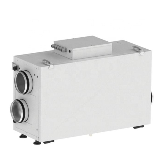
VUT/VUE 300 V2/H2 mini EC DESIGN AND FUNCTIONING The unit has the following operating principle: warm stale extract air from the room flows into the unit, where it is filtered by the extract filters, then air flows through the heat exchanger and is exhausted outside by the extract fan. Cold fresh air from the outside flows into the unit, where it is cleaned by the supply filters. -
Page 7: Mounting And Set-Up
MOUNTING AND SET-UP READ THE USER'S MANUAL BEFORE INSTALLING THE UNIT. THE UNIT MUST BE MOUNTED BY A QUALIFIED EXPERT ONLY, PROPERLY TRAINED AND HAVING THE REQUIRED TOOLS AND MATERIALS. While mounting the unit provide sufficient service access for maintenance or repair operations. When selecting a mounting location of the unit provide free opening of the service panel. -
Page 8: Weight [Kg]
VUT/VUE 300 V2/H2 mini EC 2. Attach the wall mounting brackets to the wall considering the wall material and the unit weight. 260 mm 3. Install the unit on the mounting brackets. Tighten the triangular fixing screws on the mounting brackets. SUSPENDED MOUNTING When selecting a mounting location of the unit check the minimum allowable distances to it. - Page 9 Mounting using L-shaped mounting brackets with the service panel on the bottom (only for the VUE units) The unit may be installed close to the ceiling or may be suspended using the threaded rods. Dowel Threaded rod Vibration absorbing rubber Washer Vibration absorbing rubber Screw...
-
Page 10: Vut/Vue 300 V2 Mini Ec A2
VUT/VUE 300 V2/H2 mini EC HV2 HUMIDITY SENSOR MOUNTING (ONLY FOR AIR HANDLING UNITS WITH AN A14 AUTOMATION SYSTEM) The HV2 humidity sensor is not included in the delivery set and can be ordered separately. Install the humidity sensor into the mount on the extract air duct panel and connect the humidity sensor plug to the respective socket on the control unit, refer to the External wiring diagram. - Page 11 1. Press out on the latches. Open and remove the service panel. Undo the screws securing the latches and remove them. 2. Remove four hand screws and take off the suspension brackets. Then unscrew six fixing screws from the back panel and remove the panel.
- Page 12 VUT/VUE 300 V2/H2 mini EC CONDENSATE DRAINAGE SYSTEM CONNECTION The 300 VUT V2/H2 mini EC heat recovery units require condensate drainage. The hole for the drain pipe is at the bottom of the unit. Remove the plug from the hole, open the service panel and install the drain pipe from the delivery set into the hole, then connect the drain pipe to the sewage system using the SG-32 U-trap kit (available upon separate order).
-
Page 13: Connection To Power Mains
CONNECTION TO POWER MAINS POWER OFF THE POWER SUPPLY PRIOR TO ANY OPERATIONS WITH THE UNIT. THE UNIT MUST BE CONNECTED TO POWER SUPPLY BY A QUALIFIED ELECTRICIAN. THE RATED ELECTRICAL PARAMETERS OF THE UNIT ARE GIVEN ON THE MANUFACTURER’S LABEL. ANY TAMPERING WITH THE INTERNAL CONNECTIONS IS PROHIBITED AND WILL VOID THE WARRANTY. - Page 14 VUT/VUE 300 V2/H2 mini EC Connection of the external control unit contact, such as CO sensor (NO, C) Connect the CO sensor to the terminals 6 and 7 by using a normally open dry contact. If the dry contact is closed, the unit turns to the maximum speed.
-
Page 15: Technical Maintenance
TECHNICAL MAINTENANCE DISCONNECT THE UNIT FROM POWER SUPPLY BEFORE ANY MAINTENANCE OPERATIONS! ENSURE THAT THE UNIT IS SWITCHED OFF FROM THE SUPPLY MAINS BEFORE REMOVING THE GUARD. Maintenance operations of the unit are required 3-4 times per year. This includes checking for visible damages and faults, regular cleaning and the following operations: 1. - Page 16 VUT/VUE 300 V2/H2 mini EC TECHNICAL MAINTENANCE OF THE UNIT www.ventilation-system.com...
- Page 17 TROUBLESHOOTING Problem Possible reasons Troubleshooting The fan(s) do(es) not get Make sure the power supply line is connected correctly, otherwise No power supply. started. troubleshoot the connection error. Extract filter clogging. Clean or replace the extract filter. Cold supply air. Check the heat exchanger for icing.
-
Page 18: Storage And Transportation Regulations
VUT/VUE 300 V2/H2 mini EC STORAGE AND TRANSPORTATION REGULATIONS • Store the unit in the manufacturer’s original packaging box in a dry closed ventilated premise with temperature range from +5 °C to + 40 °C and relative humidity up to 70 %. •... -
Page 19: Manufacturer's Warranty
MANUFACTURER’S WARRANTY The product is in compliance with EU norms and standards on low voltage guidelines and electromagnetic compatibility. We hereby declare that the product complies with the provisions of Electromagnetic Compatibility (EMC) Directive 2014/30/EU of the European Parliament and of the Council, Low Voltage Directive (LVD) 2014/35/EU of the European Parliament and of the Council and CE-marking Council Directive 93/68/EEC. - Page 20 VUT/VUE 300 V2/H2 mini EC www.ventilation-system.com...
- Page 21 www.ventilation-system.com...
- Page 22 VUT/VUE 300 V2/H2 mini EC www.ventilation-system.com...
-
Page 23: Certificate Of Acceptance
CERTIFICATE OF ACCEPTANCE Unit Type Heat and energy recovery air handling unit Model VUT / VUE 300___ mini EC A _____ Serial Number Manufacture Date Quality Inspector’s Stamp SELLER INFORMATION Seller Address Phone Number E-mail Purchase Date This is to certify acceptance of the complete unit delivery with the user’s manual. The warranty terms are acknowledged and accepted. - Page 24 V161EN-03...
Need help?
Do you have a question about the VUT 300 V2 MINI EC A2 and is the answer not in the manual?
Questions and answers