
Related Manuals for Vents VUE 300 HB EC


Summary of Contents for Vents VUE 300 HB EC
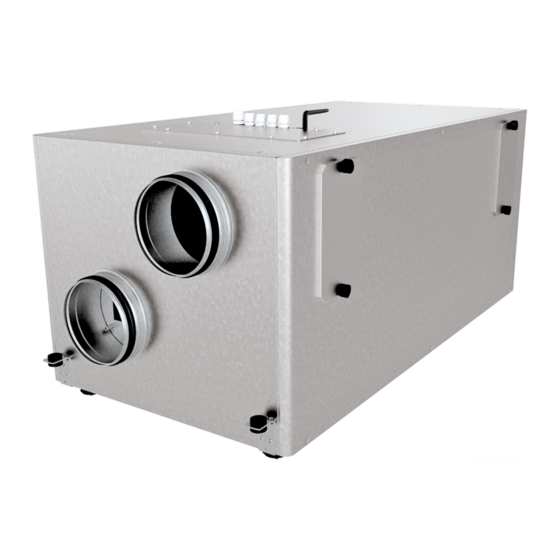
- Page 1 USER’S MANUAL VUT 300 HB(E) EC VUE 300 HB(E) EC VUT 400 HB(E) EC VUE 400 HB(E) EC VUT 700 HB(E) EC VUE 700 HB(E) EC Heat recovery air handling unit...
-
Page 2: Table Of Contents
VUT/VUE HB(E) ЕС CONTENTS Safety requirements ..................................2 Purpose ........................................ 4 Delivery set ......................................4 Designation key ....................................4 Technical data ....................................5 Unit design and operating principle ..........................6 Installation and set-up................................9 Connection to power mains ..............................11 Unit control ....................................... - Page 3 • Do not change the power cable length at your own discretion. Do not bend the power • Do not lay the power cable of the unit in cable. Avoid damaging the power cable. Do close proximity to heating equipment. not put any foreign objects on the power cable.
-
Page 4: Purpose
VUT/VUE HB(E) ЕС PURPOSE THE UNIT SHOULD NOT BE OPERATED BY CHILDREN OR PERSONS WITH REDUCED PHYSICAL, MENTAL, OR SENSORY CAPACITIES, OR THOSE WITHOUT THE APPROPRIATE TRAINING. THE UNIT MUST BE INSTALLED AND CONNECTED ONLY BY PROPERLY QUALIFIED PERSONNEL AFTER THE APPROPRIATE BRIEFING. THE CHOICE OF UNIT INSTALLATION LOCATION MUST PREVENT UNAUTHORIZED ACCESS BY UNATTENDED CHILDREN. -
Page 5: Technical Data
TECHNICAL DATA The unit is designed for indoor application with the ambient temperature ranging from +1 °C up to +40 °C and relative humidity up to 80 %. In order to prevent condensation on the internal walls of the units, it is necessary that the surface temperature of the casing is 2-3 °C higher than the dew point temperature of the transported air. -
Page 6: Unit Design And Operating Principle
VUT/VUE HB(E) ЕС Ø d Ø d Overall and connecting dimensions [mm] Model VUT/VUE 300 HB(E) ЕС 16 157 1180 1083 1126 586 566 480 540 479 506 168 193 118 190 189 189 VUT/VUE 400 HB(E) ЕС 16 197 1191 1094 1137 702 682 596 566 504 531 162 201 141 248 217 217 VUT/VUE 700 HB(E) ЕС... - Page 7 VUT ... HB EC VUE ... HB EC VUT ... HBE EC VUE ... HBE EC Air handling unit: Controller: · · · · · · Supply fan · · · · · · Extract fan · · · · ·...
- Page 8 VUT/VUE HB(E) ЕС AIR FLOW DIRECTION INTAKE AIR EXTRACT AIR EXHAUST AIR SUPPLY AIR SERVICE SIDE CHANGE Remove the plugs from the panels on the service side and on the opposite side of the unit. Undo the screws securing the panels and remove them.
-
Page 9: Installation And Set-Up
INSTALLATION AND SET-UP READ THE USER'S MANUAL BEFORE INSTALLING THE UNIT. WHILE INSTALLING THE UNIT ENSURE CONVENIENT ACCESS FOR SUBSEQUENT MAINTENANCE AND REPAIR. HV2 HUMIDITY SENSOR INSTALLATION AND CONNECTION CAUTION! The humidity sensor in the exhaust air duct should be installed and connected before the unit mounting. •... - Page 10 VUT/VUE HB(E) ЕС CONDENSATE DRAINAGE All the VUT and VUE units are equipped with a drain pan. The drain pan in energy recovery units (VUE) is not used, since condensate is not formed due to the transfer of moisture from one air stream to the other through the enthalpy membrane.
-
Page 11: Connection To Power Mains
CONNECTION TO POWER MAINS DISCONNECT THE POWER SUPPLY PRIOR TO ANY OPERATIONS WITH THE UNIT. CONNECTION OF THE UNIT TO POWER MAINS IS ALLOWED BY A QUALIFIED ELECTRICIAN WITH A WORK PERMIT FOR THE ELECTRIC UNITS UP TO 1000 V AFTER CAREFUL READING OF THE PRESENT USER’S MANUAL. - Page 12 VUT/VUE HB(E) ЕС Wiring diagram (unit with an A14 controller) 0-10V 0-10V SM1* SM2* PK1* HV2* CO * ~230 VAC Maximum cable Designation Unit name Cable type Note length SМ1* Supply air damper actuator 2x0.75 mm 20 m SМ2* Extract air damper actuator 2x0.75 mm 20 m РК1*...
-
Page 13: Unit Control
UNIT CONTROL The unit is controlled: With a wired wall control panel in units with an A14 controller (included in the delivery set). With a mobile application and/or a wired and wireless wall panel (purchased separately) in units with an A21 controller (included in the delivery set). - Page 14 VUT/VUE HB(E) ЕС 2. Heat exchanger maintenance (once per year). Some dust may accumulate on the heat exchanger even in case of regular maintenance of the filters. To maintain the high heat recovery efficiency, regular cleaning is required. To clean the heat exchanger, remove it from the unit and clean the heat exchanger by using compressed air or a vacuum cleaner.
-
Page 15: Troubleshooting
TROUBLESHOOTING PROBLEM POSSIBLE REASONS TROUBLESHOOTING Make sure the power supply line is connected No power supply. correctly, otherwise troubleshoot the connection error. The fan(s) does not start when the unit is on. Turn the unit off. Troubleshoot the motor jam and The motor is jammed, the impeller blades the impeller clogging. -
Page 16: Manufacturer's Warranty
VUT/VUE HB(E) ЕС MANUFACTURER’S WARRANTY The product is in compliance with EU norms and standards on low voltage guidelines and electromagnetic compatibility. We hereby declare that the product complies with the provisions of Electromagnetic Council Directive 2014/30/EU, Low Voltage Directive 2014/35/ EU and CE-marking Directive 93/68/EEC. -
Page 17: Certificate Of Acceptance
CERTIFICATE OF ACCEPTANCE Unit Type Heat recovery air handling unit Model VUT/VUE _________ HB(E) ЕС А___ Serial Number Manufacture Date Quality Inspector’s Stamp SELLER INFORMATION Seller Address Phone Number E-mail Purchase Date This is to certify acceptance of the complete unit delivery with the user’s manual. The warranty terms are acknowledged and accepted. - Page 18 VUT/VUE HB(E) ЕС www.ventilation-system.com...
- Page 19 www.ventilation-system.com...
- Page 20 V109-1EN-01...
Need help?
Do you have a question about the VUE 300 HB EC and is the answer not in the manual?
Questions and answers