
Subscribe to Our Youtube Channel
Related Manuals for Vents VUT 350 EH


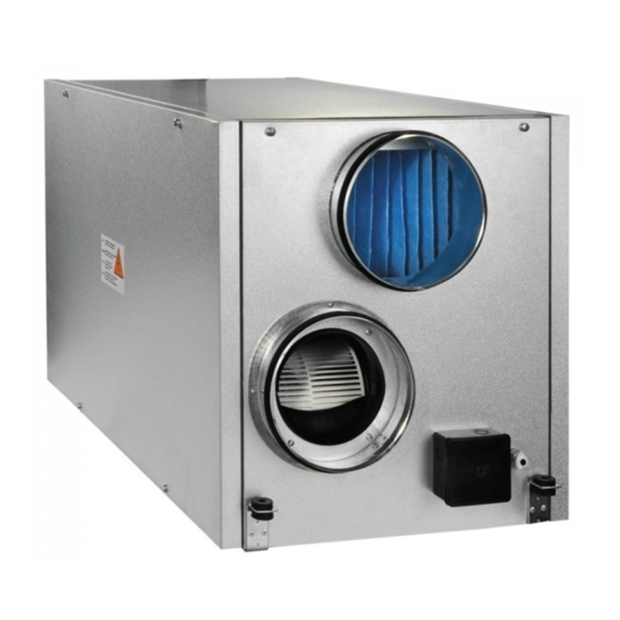
Summary of Contents for Vents VUT 350 EH
- Page 1 USER`S MANUAL VUT 350 EH VUT 800 EH VUT 500 EH VUT 1000 EH VUT 530 EH VUT 1500 EH VUT 600 EH VUT 2000 EH HEAT RECOVERY AIR HANDLING UNIT...
-
Page 2: Table Of Contents
CONTENT Introduction Delivery set Structural designation key Technical data Safety requirements Structure and operating logic Mounting and set-up Condensate drain Connection to power mains Unit control Maintenance Fault handling Storage and transportation rules Manufacturer’s warranty Acceptance certifi cate Electrical connection certifi cate Acceptance certifi cate Seller’s information Mounting certifi cate... -
Page 3: Introduction
The present user manual consisting of technical details, operating instructions and technical specifi cation covers the installation of the VUT...EH air handling unit with heat recovery, VENTS series, hereinafter referred as the unit. The unit with a heat exchanger and an electric heater is a heat recovery device and is one of the energy saving components used in buildings and premises. - Page 4 Fig. 1. VUT 350…600 EH overall and connecting dimensions Table 1 Табл. 1 Табл. 1 Dimensions [mm] Type VUT 350 EH 1057 497 100 VUT 500 EH 1057 497 100 VUT 530 EH 1057 497 100 VUT 600 EH 1057...
- Page 5 VUT EH VUT EH Ø Fig. 1. VUT 800…2000 EH overall and connecting dimensions Table 2 Dimensions [mm] Type VUT 800 EH 1117 460 1071 249 1176 832 698 613 VUT 1000 EH 1117 460 1071 249 1176 832 698 613 VUT 1500 EH 1394 581 1345 314 1447 947 814 842...
-
Page 6: Safety Requirements
Table 3 VUT 350 VUT 530 VUT 600 VUT 800 Type 500 EH 1000 EH 1500 EH 2000 EH Supply voltage, 50 Hz [V] 1~230 3~400 2 items х 2 items 2 items 2 items х 2 items 2 items х 2 items х... -
Page 7: Structure And Operating Logic
VUT EH VUT EH DESIGN AND OPERATING LOGIC The unit has the following operating logic, Fig.3: Warm stale extract air from the room fl ows through the air ducts to the unit, where it is fi ltered, then air fl ows through the heat exchanger and is exhausted outside by the extract fan through the air ducts. - Page 8 VUT 350…600 EH 1. Supply fan 2. Extract filter 3. Heat exchanger 4. Supply filter 5. Extract filter 6. Drain pipe 7. Electric heater 8. Bypass 9. Wall-mounted control panel 10. Control unit 11. Drain pan 12. Quick-detachable panels 13. Terminal box VUT 800…2000 EH Fig.
-
Page 9: Mounting And Set-Up
VUT EH VUT EH MOUNTING AND SET-UP The unit is suspended to the mounting surface through the threaded rod fi xed inside the threaded dowel. The unit is also suitable also for mounting to a horizontal mounting surface, Fig. 5. While mounting the unit provide the minimum required access to the unit for maintenance and repair. -
Page 10: Condensate Drain
Precautions: The unit is designed for mounting on a rigid and stable structure in compliance to the technical data and unit weight. The unit is mounted with anchor bolts. Make sure that a mounting construction has suffi cient load capacity for the unit weight. Otherwise reinforce an installation place by beams, etc. -
Page 11: Connection To Power Mains
VUT EH VUT EH POWER MAINS CONNECTION CONNECTION TO POWER MAINS SHALL ONLY BE PERFORMED BY QUALIFIED PERSONNEL AFTER CAREFUL READING OF THE USER’S MANUAL. THE UNIT IS INTENDED FOR AC MAINS SUPPLYING THE VOLTAGE COMPLIANT WITH THE TECHNICAL DATA TABLE. CHECK THE CABLE FOR CHOKING. - Page 12 External devices. The control panel has a built-in temperature sensor. Therefore, while installing the panel in the operating area ensure at least 1 m clearance from heating equipment, doors and windows. The panel is attached to the wall using the self-tapping screws supplied. The data cable connecting the control panel and the unit shall be routed separately from the power cables.
- Page 13 VUT EH VUT EH а) yellow green В brown А white Fig. 10. Control panel connection The temperature sensors are pre-attached by the manufacturer. For sensor connections on the controller circuit board see Fig. 11. WALL-MOUNTED CONTROL PANEL CONTROLLER CIRCUIT BOARD Terminal block on the panel Data cable...
-
Page 14: Unit Control
UNIT CONTROL 1. General description of the automatic control system. The unit is controlled via the remote-mounted control panel (Fig. 12). The physical «control panel-unit» data transfer channel is performed via a four-core data cable up to 10 m in length. The system enables supply and exhaust fan air capacity control in 3 speed increments: 1 - the minimum speed used in non-residential premises over weekends and holidays or in residential premises at night time;... - Page 15 Connect the unit to the power mains 1~230 V/50 Hz (for VUT 350..600 EH units) or 3~400 V/50 Hz (for VUT 800..2000 EH units). For details, refer to connection to power mains, Page 11. The indicator displays the “VENTS” logo, the LEDs are off .
- Page 16 Fan speed Controlled temperature Room Vent. Heat. User-defined controlled temperature Clock Current operation mode Heater power Fig. 13. RC main operation window The unit has two temperature control modes: air temperature on the premises, the «large circuit», and the air temperature in the supply duct, the «small circuit».
- Page 17 VUT EH VUT EH The main menu enables the user to change the critical unit operation parameters such as: «Temperature Setting» Changing the control temperature value ( buttons). Temperature setting Speed stage Service menu Temperature «Speed stage» Changing the fan speed ( buttons).
- Page 18 Filter replacement after 78 days Filter replacement message: Replace fi lter The reminder message pops up periodically for a brief time replacing the main operation window (the red LED will blink). To acknowledge the reminder enter the «Filter Replacement Timer» menu and press the button.
- Page 19 VUT EH VUT EH MONDAY 23:00-08:00 08:00-23:00 To select the user-defi ned position (day of the week, timer status on the day - on/off , unit operation time in the mode, controlled temperature, and fan speed) use the button. To change the selected entry press buttons.
-
Page 20: Maintenance
7. Emergency Alarms. On triggering of either the sensor thermal switch deenergizing the heating elements or in case of fi lter clogging (which triggers the diff erential pressure sensor) or communication line damage the unit enters the emergency «Electric heating elements blowing» mode with subsequent shutdown in 2 minutes. -
Page 21: Fault Handling
VUT EH VUT EH TROUBLESHOOTING Table 5 Possible faults and troubleshooting Fault Possible reasons Fault handling Make sure that the unit is properly connected to power mains and make No power supply. any corrections, if necessary. The fan does not start up during Turn the unit off . -
Page 22: Storage And Transportation Rules
MANUFACTURER’S WARRANTY The manufacturer hereby warrants normal operation of the unit over the period of 24 months from the retail sale date provided the user’s observance of the transportation, storage, installation and operation regulations. Should any malfunctions occur during the unit operation through the manufacturer’s fault during the warranty period the user is entitled to elimination of faults by means of warranty repair performed by the manufacturer. -
Page 23: Acceptance Certificate
VUT EH VUT EH ACCEPTANCE CERTIFICATE Product Type Air handling unit with heat recovery Model VUT__________EH Serial Number Manufacturing Date is compliant with the technical specifi cations and is hereby declared ready for service. Quality Inspector’s Stamp SELLER’S INFORMATION Shop name Address Phone number E-mail... -
Page 24: Warranty Card
WARRANTY CARD Product type Air handling unit with heat recovery Model VUT__________EH Serial number Manufacturing date Sales date Warranty period Sales company Seller’s seal... - Page 25 V28EN-04...
Need help?
Do you have a question about the VUT 350 EH and is the answer not in the manual?
Questions and answers