
Related Manuals for Vents VUT 350 H


Summary of Contents for Vents VUT 350 H
- Page 1 РУКОВОДСТВО ПОльзОВаТеля РУКОВОДСТВО ПОльзОВаТеля USER’S MANUAL VUT 350 H VUT 600 H VUT 500 H VUT 1000 H VUT 530 H VUT 2000 H HEAT RECOVERY AIR HANDLING UNIT...
-
Page 2: Table Of Contents
CONTENTS Safety requirements Introduction Delivery set Designation key Technical data Unit design and operating logic Mounting and set-up Condensate drainage Connection to power mains Unit control Maintenance Fault handling Storage and transportation rules Manufacturer's warranty Acceptance certificate Seller information Connection certificate Warranty card... -
Page 3: Safety Requirements
SAFETY REQUIREMENTS • Read the user’s manual carefully prior to the operation and installation of the VUT … H heat recovery air handling unit. • Fulfil the user’s manual requirements as well as the provisions of all the applicable local and national construction, electrical and technical codes and standards. - Page 4 Use the unit only as intended by Do not touch the unit controls the manufacturer. with wet hands. Do not connect a clothes dryer or Do not carry out the unit mainte- other similar equipment to the nance with wet hands. unit or the ventilation system.
-
Page 5: Introduction
INTRODUCTION This user’s manual includes technical description, operation, installation and mounting guidelines, technical data for the VUT … H heat recovery air handling unit, hereinafter referred to as “the unit”. • Due to the ability to save heating energy by means of energy recovery the unit is an important energy saving element used in the buildings and premises. -
Page 6: Technical Data
The unit design is constantly being improved, so some models can slightly differ from those ones described in this manual. Unit overall and connecting dimension Dimensions [mm] Model ØD VUT 350 H VUT 500 H VUT 530 H VUT 600 H VUT 1000 H... - Page 7 SF VUT 1000 SF VUT 2000 Replaceable filter F7* SF VUT 350-600 H F7 H F7 H F7 VL VUT1000 VL VUT2000 Summer block* VL VUT 350 H VL VUT 500-600 H Connected air duct diameter [mm] Ø125 Ø150 Ø160 Ø200 Ø250 Ø315...
-
Page 8: Unit Design And Operating Logic
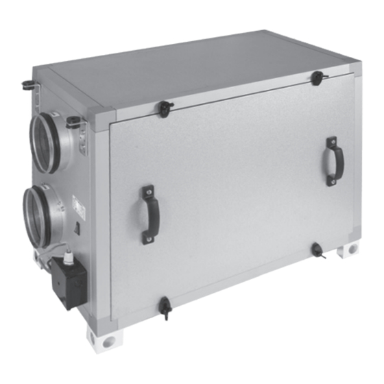
UNIT DESIGN AND OPERATING LOGIC Unit operation logic: warm stale extract air from the room flows to the unit, where it is filtered, then air flows through the heat exchanger and is exhausted outside by the extract fan. Clean cold air from outside is moved to the supply filter. Then filtered air flows through the heat exchanger and is moved to the room with the supply fan. -
Page 9: Mounting And Set-Up
MOUNTING AND SET-UP The unit may be suspended on threaded rods that are fixed inside a dowel or may be rigidly fixed on a horizontal plane. While mount- ing the unit provide enough access for maintenance or repair work. Unit ceiling mounting Unit oor mounting Safety precautions:... -
Page 10: Condensate Drainage
Connect the switch according to the wiring diagram (see page 12). Place the executive part of the switch into the mounting box. Secure the executive part of the switch by means of two screws (included in the delivery set). Cover the executive part of the switch with the decorative front panel and secure the panel by pressing the panel surface over the latches until they snap in place. -
Page 11: Connection To Power Mains
Recommended rated current of the circuit breaker depending on the unit model: Unit model Rated current of the circuit breaker [A] VUT 350 H VUT 500 H VUT 530 H VUT 600 H VUT 1000 H VUT 2000 H The conductor cross section is 0.75 mm... -
Page 12: Unit Control
VUT ... H air-handling units must be connected to the power mains in accordance with the wiring diagram and the terminal designations given inside the terminal box or the control unit: VUT 350 ... 600 H VUT 1000 ... 2000 H electrical connections diagram electrical connections diagram Control unit... -
Page 13: Maintenance
MAINTENANCE The unit must undergo technical maintenance 3 to 4 times a year. Maintenance includes general cleaning of the unit and the following operations: 1. Filter maintenance (3-4 times per year). Dirty filters increase air resistance in the system and reduce supply air volume. The filters require cleaning not less than 3-4 times per year. -
Page 14: Fault Handling
6. Technical maintenance of air duct system (every 5 years). Even regular fulfilling of all the prescribed above maintenance operations may not completely prevent dirt accumulation in the air ducts which reduces the unit capacity. The air duct maintenance includes their periodic cleaning or replacement. 7. -
Page 15: Manufacturer's Warranty
MANUFACTURER’S WARRANTY The manufacturer hereby warrants normal operation of the unit over the period of 24 months from the retail sale date provided the user’s observance of the transportation, storage, installation and operation regulations. Should any malfunctions occur during the unit operation due to manufacturer’s fault during the warranty period the user is entitled to elimination of faults by means of warranty repair performed by the manufacturer. -
Page 16: Acceptance Certificate
ACCEPTANCE CERTIFICATE Product Type Heat recovery air handling unit Model VUT______ H Serial Number Manufacturing Date We hereby declare that the product complies with the essential protection requirements of Electromagnetic Council Directive 2004/108/EC, 89/336/EEC and Low Voltage Directive 2006/95/EC, 73/23/EEC and CE-marking Directive 93/68/EEC on the approximation of the laws of the Member States relating to electromagnetic compatibility. -
Page 17: Warranty Card
WARRANTY CARD Product type Heat recovery air handling unit Model VUT______H Serial number Manufacturing date Sales date Warranty period Sales company Seller’s seal NOTES _________________________________________________________________________________________________ _________________________________________________________________________________________________ _________________________________________________________________________________________________ _________________________________________________________________________________________________ _________________________________________________________________________________________________ _________________________________________________________________________________________________ _________________________________________________________________________________________________ ________________________________________________________________________________________... - Page 18 V26EN-02...
Need help?
Do you have a question about the VUT 350 H and is the answer not in the manual?
Questions and answers