Table of Contents
Advertisement
Quick Links
Advertisement
Table of Contents

Related Manuals for Vents VUT EH EC Series


Summary of Contents for Vents VUT EH EC Series
-
Page 1: Content
VUT EH EC VUT EH EC USER'S MANUAL... -
Page 2: Table Of Contents
VUT EH EC VUT EH EC Introduction ð. 3 CONTENT ð. 3 Purpose ð. 3 Delivery set ð. 4 Designation key ð. 4 Parameters and dimensions ð. 6 Technical data ð. 8 Safety requirements ð. 9 Design and functioning ð. 11 Mounting and set-up ð. -
Page 3: Introduction Ð
VENTS VUT EH EC, hereinafter " the unit". Due to the ability to save heating energy by means of energy recovery the unit is an important PURPOSE element of energy-efficient premises. -
Page 4: Designation Key Ð
Ventilation unit with heat recovery and air capacity 300 m3/h, horizontally directed 160 mm spigots, equipped with an electric heater and EC motors: VENTS VUT 300-2 EH EC. The basic unit dimensions are stated in Table 1 and in Fig. 1. - Page 5 VUT EH EC VUT EH EC ØD Fig. 1 Dimensions [mm] Model Ø D 1092 1137 1198 VUT 300-1 EH EC VUT 300-2 EH EC 1092 1137 1198 1092 1137 1198 VUT 400 EH EC 1092 1137 1198 VUT 600 EH EC Table 1.
-
Page 6: Technical Data Ð
VUT EH EC VUT EH EC The unit is rated for indoor application with the ambient temperatures from +1°C up to +40°C TECHNICAL and relative humidity of up to 80%. DATA Hazardous parts access and water ingress protection ratings: Unit motors - IP 44; Unit assembly connected to air ducts - IP 22. - Page 7 VUT EH EC VUT EH EC EH EC EH EC Unit supply voltage, 50/60 Hz [V] 1~ 230 Max. fan power [W] 2 items x 175 Fan current [A] 2 items x 1,3 Electric heater power [kW] Electric heater current [A] 17,4 Total unit power [kW] 4,35...
-
Page 8: Safety Requirements Ð
VUT EH EC VUT EH EC Read the user's manual carefully prior to installing and operating the heat recovery SAFETY air handling unit, hereinafter referred as the unit. REQUIREMENTS Fulfil the user's manual requirements as well as the provisions of all the applicable local and national construction, electrical and technical norms and standards. -
Page 9: Design And Functioning Ð
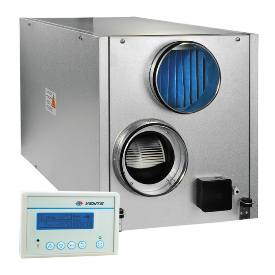
VUT EH EC VUT EH EC The unit operates as follows: UNIT DESIGN Warm stale extract air from the room flows to the unit, where it is filtered, then air flows AND OPERATING through the heat exchanger and is exhausted outside by the extract fan. LOGIC Clean cold air from outside is moved by the supply filter. - Page 10 VUT EH EC VUT EH EC The basic unit complete set includes: - remote-mounted control panel 9 that is connected via the data cable 12 to the integrated control system in the unit; - a supply 1 and an extract 2 centrifugal single-intake fans with backward curved blades and maintenance-free external rotor motors with built-in overheating protection.
- Page 11 VUT EH EC VUT EH EC VENTS … EH EC UNIT DESIGN Extract air Intake air Supply air Exhaust air Fig. 2 1 - Supply fan; 8 - Bypass damper; 2 - Extract fan; 9 - Remote-mounted control panel; 3 - Plate counter-flow heat exchanger;...
-
Page 12: Mounting And Set-Up Ð
VUT EH EC VUT EH EC The unit is designed for ceiling mounting by means of the threaded rod fixed inside the MOUNTING threaded dowel (Fig. 3). Optionally, it may be rigidly fixed on a horizontal even surface AND SET-UP (Fig. -
Page 13: Condensate Drainage
VUT EH EC VUT EH EC After the unit mounting it must be connected to a drain system as shown in Fig. 6. CONDENSATE The unit must be sloped down toward the drain pipe by 1-2°. DRAINAGE Connect the drain pipe (1), the U-trap (3) and the sewerage system (5) with metal, plastic or rubber hoses. - Page 14 VUT EH EC VUT EH EC Do not connect several drain pipes from several air handling units to a single U-trap! WARNING Direct condensate drainage outside without connection to sewage system is not allowed.
- Page 15 VUT EH EC VUT EH EC Disconnect the unit from power supply prior to any electric installation operations. CONNECTION Installation shall only be performed by a professional electrician. The rated electrical TO POWER parameters are stated on the rating plate. Any tampering with the internal connections MAINS is prohibited and will void the warranty.
- Page 16 VUT EH EC VUT EH EC ~230 V, 50/60 Hz Fig. 7 The temperature sensor is integrated in the control panel. Therefore, the installation place CONNECTION of the control panel must be at least 1 m away from heating equipment, doors and windows. OF CONTROL Attach the control panel to the wall using the supplied screws.
- Page 17 VUT EH EC VUT EH EC c) Strip the cable of the protective insulation (~20 mm); d) Strip the wires of the protective insulation (~6 mm); e) Attach the wires to the terminal block on the control board according to the markings on the sticker and the wire colouring: Black ………..
- Page 18 VUT EH EC VUT EH EC Functional capabilities. The system enables to control air capacity of the supply and extract fan in 3 speed steps: 1 - low speed; 2 - medium speed; 3 - maximum speed. 2. The temperature sensors enable to select the most suitable operation mode for maintaining a pre-set air temperature in the air duct.
-
Page 19: Unit Activation/ Deactivation
Connect the unit to the power mains 1~230 V/50/60 Hz (for details, refer to connection UNIT to power mains).The indicator displays the “VENTS” logo, the LED indicators are off. ACTIVATION/ To activate the unit press the Power button, select On and press the Enter button. -
Page 20: Control Ð
VUT EH EC VUT EH EC Service functions. The service functions of the control system are as follows: 1. The week scheduled program enables automatic programming of the user-defined parameters as indoor temperature, fan speed for each week day and current time. This function provides automatic changeover between day and night modes as well as "week days"... -
Page 21: Control Panel Operation Ð
VUT EH EC VUT EH EC 5. "Down" button is used for going down in the list of menu or decreasing the current parameter. 6. "Enter" button is used for selection of an editable parameter or moving to a previous menu level. - Page 22 VUT EH EC VUT EH EC “Temperature setting” Enables to edit the control temperature value with the Up/Down buttons. “Fan speed “ Enables to edit the fan speed stage with the Up/Down buttons.
- Page 23 VUT EH EC VUT EH EC The service menu is used to use and adjust the service functions: Date and time settings are required to ensure the correct operation of the day timer and the week timer. To select the item to be edited (year, month, date, day, hour, minute) press Enter. To edit the current value of the menu item use the Up/Down buttons.
- Page 24 VUT EH EC VUT EH EC Use the Up/Down buttons to set the filter replacement periodicity. The filter replacement warning indicator is displayed instead of the main working window for some time. Synchronously the red LED indicator blinks. To deactivate the filter replacement indicator enter the menu item "Filter replacement timer"...
- Page 25 VUT EH EC VUT EH EC Is used to set turning ON and turning OFF time for the air handling unit. When this mode is activated the unit turns on and off in set time every day till this mode is deactivated.
- Page 26 VUT EH EC VUT EH EC The day timer settings have higher priority as compared to the week timer. WARNING If the day timer is activated the item "Operation mode" in the main window will display the symbol "D". To select the item to be edited (week day, on/off timer status for this day, operation time in this mode, control temperature, fan speed) press Enter.
- Page 27 VUT EH EC VUT EH EC FRIDAY Set the room temperature 25 °C from 09:00 till 22:00 and set the maximum speed for the supply fan. Set the room temperature 19 °C from 22:00 till 09:00 and set the minimum speed for the supply fan.
- Page 28 VUT EH EC VUT EH EC Operation mode programming for TUESDAY: In the week day selection window, first line, set "TUESDAY" using the Up/Down buttons and press Enter. The cursor bar goes to the timer status for the selected week day. Set "ON"...
- Page 29 VUT EH EC VUT EH EC Operation mode programming for FRIDAY: In the week day selection window, first line, set "FRIDAY" using the Up/Down buttons and press Enter. The cursor bar goes to the timer status for the selected week day. Set "ON"...
- Page 30 VUT EH EC VUT EH EC "Season mode" This mode is applicable only for the unit with a heat exchanger and a bypass damper In "heat recovery (winter) mode" the bypass damper is closed and the intake air stream flows through the heat exchanger. In case of a freezing danger of the heat exchanger, if the intake air temperature is below -9 °C, the bypass damper is open for 5 minutes and closed for 25 minutes.
-
Page 31: Unit Programming With The External Control Panel Ð
VUT EH EC VUT EH EC Select the required position using the Up/Down buttons or the Power button and then press Enter to bring the unit to the required status (on/off). The procedure of the unit turning on is the following: the electric heater is turned off, the fan switches to low speed for heater cooling. -
Page 32: Error Status Ð
VUT EH EC VUT EH EC The unit requires maintenance works 3-4 times per year. Maintenance includes regular MAINTENANCE cleaning and the following operations: 1. Filter maintenance. Contaminated filters increase air resistance in the system and reduce supply air volume. Clean the filters once in 3-4 months. - Page 33 VUT EH EC VUT EH EC 5. Extract shutters and supply diffuser cleaning (as required). Remove the diffusers and louvre shutters and wash those with hot soap water. Do not change the mounting position of the diffusers and the shutters. 6.
-
Page 34: Maintenance Ð
VUT EH EC VUT EH EC TROUBLE- Possible Problem Remedy SHOOTING reasons The fan does Motor jam in one or both Turn the unit off. Troubleshoot the fans. motor jam. Restart the unit. not move up Wrong wiring of the control during start-up panel or any other unit of the unit. - Page 35 VUT EH EC VUT EH EC Possible Problem Remedy reasons Cold air flow. Contaminated filters. Clean or replace the filters. Heat exchanger icing. Check the heat exchanger for icing. Tripping of the temperature In case of the heat exchanger icing switch.
-
Page 36: Troubleshooting Ð
VUT EH EC VUT EH EC Store the unit in the manufacturer's original packing box in a dry ventilated premise at STORAGE AND ambient temperatures from +10 °C up to +40 °C at max. RH 60% at +20 °C. TRANSPORTATION Storage environment must not contain aggressive vapours and chemical mixtures provoking REGULATIONS corrosion, insulation and sealing deformation. -
Page 37: Manufacturer's Warranty And Acceptance Certificate Ð
VUT EH EC VUT EH EC The MANUFACTURER is not responsible for any mechanical or physical damages WARNING resulting from the manual requirements violence, the unit misuse or gross mechanical effect. Fulfil the requirements set in the user's manual to ensure proper functioning of the unit. -
Page 38: Seller Information Ð
VUT EH EC VUT EH EC SELLER INFORMATION Outlet Name Address Phone Number E-mail Purchase Date Seller's Stamp This is to certify acceptance of the complete unit delivery with the user's manual. The warranty terms are acknowledged and accepted. Customer's Signature INSTALLATION CERTIFICATE The heat recovery air handling unit VUT _________ EH EC has been... -
Page 39: Warranty Card Ð
VUT EH EC VUT EH EC WARRANTY CARD Heat recovery air handling unit Unit type VUT ____ EH EC Model Serial Number Purchase Date Purchase Date Warranty Period Seller's Stamp Seller... - Page 40 VUT EH EC VUT EH EC V41EN-03...
Need help?
Do you have a question about the VUT EH EC Series and is the answer not in the manual?
Questions and answers