
Related Manuals for Vents VUT 350 PE EC


Summary of Contents for Vents VUT 350 PE EC
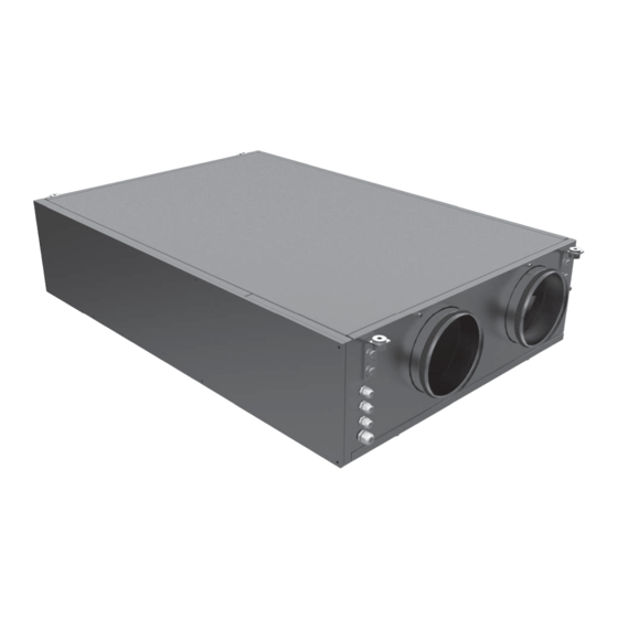
- Page 1 USER’S MANUAL VUT 350 PE EC VUT 600 PE EC VUT 1000 PE EC HEAT RECOVERY AIR HANDLING UNIT...
-
Page 2: Table Of Contents
VUT .. PE EC VUT .. PE EC CONTENTS Safety requirements Introduction Delivery set Designation key Technical parameters Design and operating logic Mounting and set-up Condensate drain Connection to power mains Unit control Maintenance Troubleshooting Storage and transportation rules Manufacturer's warranty Acceptance certifi cate Seller's information Mounting certifi cate... -
Page 3: Safety Requirements
SAFETY REQUIREMENTS • Read the user’s manual carefully prior to the operation and installation of the heat recovery air handling unit, hereinafter the unit. • Installation and operation of the unit shall be performed in accordance with the present user’s manual as well as the provisions of all the applicable local and national construction, electrical and technical codes and standards. - Page 4 VUT .. PE EC VUT .. PE EC UNIT OPERATION SAFETY PRECAUTIONS Do not touch the unit control speed or the Do not wash the unit with water. control panel with wet hands. Do not carry out Protect the unit electric parts from water the unit maintenance with wet hands.
-
Page 5: Introduction
This user’s manual includes technical description, operation, installation and mounting guidelines, technical data for the heat recovery air handling unit VENTS VUT PE EC, hereinafter referred as the unit. The unit with heat recovery and electric heater is designed to save heat energy by means of heat recovery and is one of the energy saving components used in the buildings and premises. - Page 6 VUT .. PE EC VUT .. PE EC UNIT OVERALL DIMENSIONS, MM Fig. 1. VUT 350 PE EC overall dimensions Fig. 2. VUT 600 (1000) PE EC overall dimensions Model VUT 350 PE EC VUT 600 PE EC VUT 1000 PE EC Ø...
-
Page 7: Design And Operating Logic
Some condensate may be generated during heat recovery. The condensed fl uid is collected in the drain pan and is removed from the unit through the drain hoses. UNIT DESIGN BASED on VUT 350 PE EC EXTRACT FAN BYPASS SUPPLY FILTER... -
Page 8: Mounting And Set-Up
VUT 1000 PE ЕС min А, mm min A depends on the fi lter VUT 350 PE EC - 441 mm; VUT 600 PE EC - 784 mm; VUT 1000 PE EC - 650 mm (less than VUT 600 PE EC). -
Page 9: Condensate Drain
UNIT MODIFICATIONS The unit is available with the service side located on the left and on the right of the unit to facilitate mounting and provide minimum service access. RIGHT-HAND MODIFICATION LEFT-HAND MODIFICATION (TOP VIEW) (TOP VIEW) Safety precautions The unit is designed for mounting on a rigid and stable structure. The unit is mounted with anchor bolts. - Page 10 Then fi x the sensor with the clamp and the holder in the extract air duct upstream of the heat exchanger. Duct humidity sensor installation place Duct humidity sensor installation place VUT 350 PE EC VUT 600(1000) PE EC Duct humidity sensor connection...
-
Page 11: Connection To Power Mains
CONNECTION TO POWER MAINS DISCONNECT THE UNIT FROM POWER MAINS PRIOR TO ANY ELECTRIC INSTALLATION OPERATIONS. CONNECT THE UNIT TO A CORRECT INSTALLED SOCKET WITH A GROUNDED TERMINAL. THE RATED ELECTRICAL PARAMETERS OF THE UNIT ARE GIVEN ON THE MANUFACTURER’S LABEL. ANY INTERNAL CONNECTION MODIFICATIONS ARE NOT ALLOWED AND RESULT IN WARRANTY LOSS. -
Page 12: Unit Control
VUT .. PE EC VUT .. PE EC EXTERNAL WIRING DIAGRAM 11 10 Х1 +12V Gnd +12V Р1 − ELECTRIC SHOCK HAZARD! 1. The unit delivery set includes P1 and TE1 only. 2. ** Maximum connecting cable length is 20 m! Design. - Page 13 2. Heat exchanger maintenance (once a year). Even regular fi lter technical maintenance may not completely prevent dirt accumulation on the heat exchanger unit. Clean the heat exchanger on a regular basis to ensure its high heat recovery effi ciency. To clean the heat exchanger remove it from the unit and wash it with warm neutral detergent solution.
-
Page 14: Troubleshooting
VUT .. PE EC VUT .. PE EC 4. Condensate drain maintenance (once a year). The drain pipes may get clogged with the extracted particles. Pour some water inside the drain pan and check the pipe for clogging. Clean the U-trap and drain pipe if required. 5. -
Page 15: Manufacturer's Warranty
MANUFACTURER’S WARRANTY The manufacturer hereby warrants normal operation of the unit over the period of 24 months from the retail sale date provided the user’s observance of the transportation, storage, installation and operation regulations. Should any malfunctions occur during the unit operation through the manufacturer’s fault during the warranty period the user is entitled to elimination of faults by means of warranty repair performed by the manufacturer. -
Page 16: Vut
VUT .. PE EC VUT .. PE EC ACCEPTANCE CERTIFICATE Product Type Heat recovery air handling unit Model VUT______PE EC______ Serial Number Manufacturing Date is compliant with the technical specifi cations and is hereby declared ready for service. We hereby declare that the product complies with the essential protection requirements of Electromagnetic Council Directive 2004/108/EC, 89/336/EEC and Low Voltage Directive 2006/95/EC, 73/23/EEC and CE-marking Directive 93/68/EEC on the approximation of the laws of the Member States relating to electromagnetic compatibility. -
Page 17: Warranty Card
WARRANTY CARD Product type Heat recovery air handling unit Model VUT______PE EC ______ Serial number Manufacturing date Sales date Warranty period Sales company Seller’s seal ______________________________________________________________________________________________________ ______________________________________________________________________________________________________ ______________________________________________________________________________________________________ ______________________________________________________________________________________________________ ______________________________________________________________________________________________________ ______________________________________________________________________________________________________ ______________________________________________________________________________________________________ _________________________________________________________________________________________________... - Page 18 VUT .. PE EC VUT .. PE EC...
- Page 20 V68EN-08...
Need help?
Do you have a question about the VUT 350 PE EC and is the answer not in the manual?
Questions and answers