
Subscribe to Our Youtube Channel
Related Manuals for Vents VUT 350 EH


Summary of Contents for Vents VUT 350 EH
- Page 1 USER'S MANUAL VUT 350 EH VUT 800 EH VUT 500 EH VUT 1000 EH VUT 530 EH VUT 1500 EH VUT 600 EH VUT 2000 EH Heat recovery air handling unit...
-
Page 2: Table Of Contents
VUT 350/500/530/600/800/1000/1500/2000 EH CONTENTS Purpose ........................................ 4 Delivery set ......................................4 Designation key ....................................4 Technical data ....................................5 Design and operating principle ............................7 Mounting and set-up .................................. 9 Connection to power mains ..............................11 Technical maintenance ................................12 Storage and transportation regulations .......................... - Page 3 • Do not change the power cable length at your own discretion. Do not bend the • Do not lay the power cable of the unit in power cable. Avoid damaging the power close proximity to heating equipment. cable. Do not put any foreign objects on the power cable.
-
Page 4: Purpose
VUT 350/500/530/600/800/1000/1500/2000 EH PURPOSE The unit is designed to ensure continuous mechanical air exchange in houses, offices, hotels, cafes, conference halls, and other utility and public spaces as well as to recover the heat energy contained in the air extracted from the premises to warm up the filtered stream of intake air. -
Page 5: Technical Data
The unit design is constantly being improved, thus some models may be slightly different from those described in this manual. OVERALL DIMENSIONS OF THE UNIT [MM] VUT EH 350...600 Dimensions [mm] Model VUT 350 EH 1060 VUT 500 EH 1060 VUT 530 EH... - Page 6 VUT 350/500/530/600/800/1000/1500/2000 EH Ø VUT EH 800...2000 Dimensions [mm] Model VUT 800 EH 1117 1071 1176 VUT 1000 EH 1117 1071 1176 VUT 1500 EH 1394 1345 1447 VUT 2000 EH 1394 1345 1447 TECHNICAL DATA Model Voltage [V/50 Hz] 1~230 3~400 2 pcs.
-
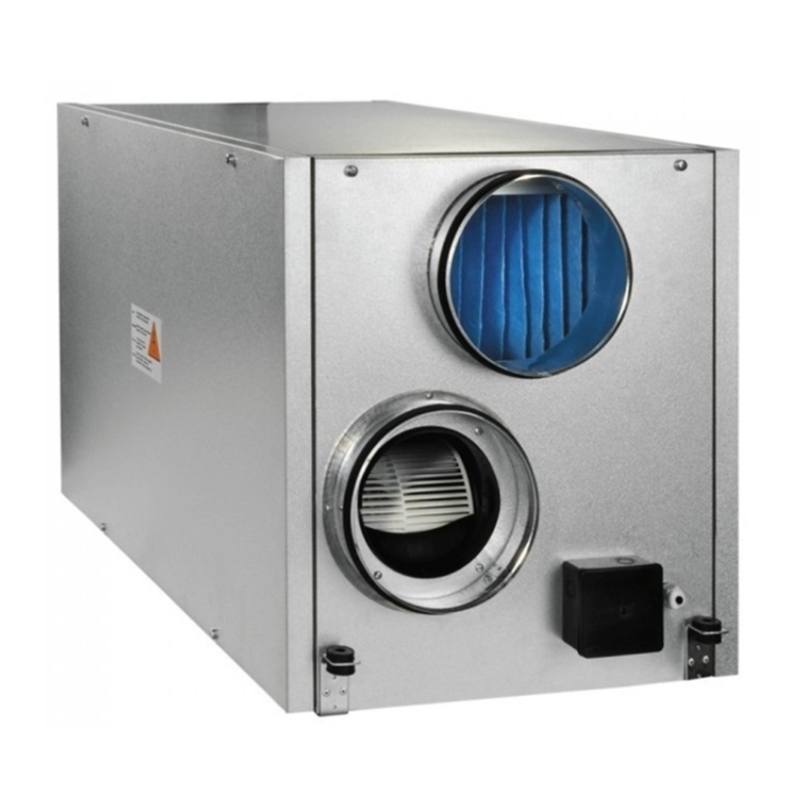
Page 7: Design And Operating Principle
DESIGN AND OPERATING PRINCIPLE The unit has the following operating principle: Warm stale extract air from the room flows to the unit, where it is filtered, then air flows through the heat exchanger and is exhausted outside by the extract fan. Clean cold air from outside is moved to the supply filter. Then filtered air flows through the heat exchanger and is moved to the room with the supply fan. - Page 8 VUT 350/500/530/600/800/1000/1500/2000 EH VUT 350...600 EH 1. Supply fan 2. Extract fan 3. Heat exchanger 4. Supply air lter 5. Extract air lter 6. Drain pipe 7. Electric heater 8. Bypass 9. Wall control panel 10. Control unit 11. Drain pan 12.
-
Page 9: Mounting And Set-Up
MOUNTING AND SET-UP READ THE USER'S MANUAL BEFORE INSTALLING THE UNIT. The unit may be suspended on threaded rods that are fixed inside dowels or may be rigidly fixed on a horizontal plane. Example Washer Vibration absorbing rubber Nut and Unit mounting lock nut on a horizontal plane... - Page 10 VUT 350/500/530/600/800/1000/1500/2000 EH If the bolts used for the unit mounting are too short, the unit can generate abnormal noise and resonate with the ceiling. If the abnormal noise is generated at the spiral air duct joint replace the spiral air duct with a flexible one to prevent resonance. The precautionary measures described above should eliminate the problem of resonance.
-
Page 11: Connection To Power Mains
CONNECTION TO POWER MAINS POWER OFF THE POWER SUPPLY PRIOR TO ANY OPERATIONS WITH THE UNIT. THE UNIT MUST BE CONNECTED TO POWER SUPPLY BY A QUALIFIED ELECTRICIAN. THE RATED ELECTRICAL PARAMETERS OF THE UNIT ARE GIVEN ON THE MANUFACTURER’S LABEL. ANY TAMPERING WITH THE INTERNAL CONNECTIONS IS PROHIBITED AND WILL VOID THE WARRANTY. -
Page 12: Technical Maintenance
VUT 350/500/530/600/800/1000/1500/2000 EH TECHNICAL MAINTENANCE DISCONNECT THE UNIT FROM POWER SUPPLY BEFORE ANY MAINTENANCE OPERATIONS! Maintenance operations of the unit are required 3-4 times per year. 1. Filter maintenance (3-4 times per year). Dirty filters increase air resistance in the system and reduce supply air volume. The filters require cleaning not less than 3-4 times per year. Clean the filter with a vacuum cleaner or replace it with a new one. -
Page 13: Storage And Transportation Regulations
TROUBLESHOOTING Problem Possible reasons Troubleshooting Make sure the power supply line is connected correctly, No power supply. otherwise troubleshoot the connection error. Turn the unit off. Troubleshoot the motor jam and the The motor is jammed, the impeller blades are soiled. The fan(s) does not start impeller clogging. -
Page 14: Manufacturer's Warranty
VUT 350/500/530/600/800/1000/1500/2000 EH MANUFACTURER’S WARRANTY The product is in compliance with EU norms and standards on low voltage guidelines and electromagnetic compatibility. We hereby declare that the product complies with the provisions of Electromagnetic Council Directive 2014/30/EU, Low Voltage Directive 2014/35/ EU and CE-marking Directive 93/68/EEC. -
Page 15: Certificate Of Acceptance
CERTIFICATE OF ACCEPTANCE Unit Type Heat recovery air handling unit Model VUT_____EH Serial Number Manufacture Date Quality Inspector’s Stamp SELLER INFORMATION Seller Address Phone Number E-mail Purchase Date This is to certify acceptance of the complete unit delivery with the user’s manual. The warranty terms are acknowledged and accepted. - Page 16 V28EN-06...
Need help?
Do you have a question about the VUT 350 EH and is the answer not in the manual?
Questions and answers