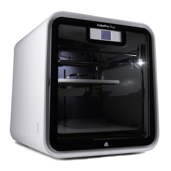
3D Systems CubePro Original Instructions Manual
Hide thumbs
Also See for CubePro:
- User manual (89 pages) ,
- Replacement manual (52 pages) ,
- Repair manual (40 pages)
Subscribe to Our Youtube Channel
Summary of Contents for 3D Systems CubePro
- Page 1 CubePro ™ Prosumer 3D Printer Power Supply Replacement Guide Original Instructions...
-
Page 2: Fcc Notice
3D Systems, Inc. Cubify, and the 3D Systems logo are registered trademarks of 3D Systems, Inc. CubePro is a trademark of 3D Systems, Inc. Use of the Cubify.com website constitutes acceptance of its Terms of Service and Privacy Policy. -
Page 3: Warranty
CubePro 3D Printer. The warranty period for the CubePro 3D printer is the shorter of (i) 90 days from the date your CubePro 3D printer is activated or (ii) 24 months after the CubePro 3D Printer is shipped from 3D Systems to the end customer or intermediary. -
Page 4: Important Safety Information
Follow all safety rules in this section and observe all cautions and warnings in this guide. • Do not modify any safety features or make modifications to the CubePro. Doing so is prohibited and voids the warranty. • Use of print materials other than genuine 3D Systems components may void the warranty. - Page 5 AT A GLANCE Inner Floor Outer Floor Power Supply 3D Systems, Inc.
-
Page 6: Positive Connection
Direct Current Side Positive Connection Negative Connection Positive Connection Negative Connection 401894 - Gray Wire 401884 - Green Wire and Yellow Wire Main PCB Fan - Red Wire Main PCB Fan - Black Wire 401889-00 - Green Wire 3D Systems, Inc. - Page 7 Rear Alternating Current Side 401882 - Blue Wire and Brown Wire 401883 - Green/Yellow Wire 3D Systems, Inc.
-
Page 8: Replacing The Power Supply
WARNING: THE PRINTER MUST BE DISCONNECTED FROM UTILITY POWER BEFORE PROCEEDING. Using a 3 mm hex head driver, loosen and remove all nine (9) 3mm hex head bolts securing the inner floor. Retain the screws for reassembly. 3D Systems, Inc. - Page 9 NOTE: Make note of each connection so they will be reconnected properly during reassembly. Remove the 401883 blade connector (A) from the blade terminal. Carefully disconnect 401882 (B), the two (2) pin connector, from the power supply. 3D Systems, Inc.
- Page 10 NOTE: Depending on your printer model, some junctions may not be used. Refer to your notes and the connections diagram on page 4. If you need further assistance, contact support. 3D Systems, Inc.
- Page 11 18. Insert the original nine (9) screws that were removed in step 5 and secure them using a 3 mm hex driver. 19. Connect the power cord to the printer and turn on the main power switch. Press the on/off button to turn on the display. 3D Systems, Inc.
- Page 12 3D Systems, Inc. 333 Three D Systems Circle | Rock Hill, SC | 29730 www.3dsystems.com ©2014 3D Systems, Inc. All rights reserved. PN: 403169-00 Rev. A...


Need help?
Do you have a question about the CubePro and is the answer not in the manual?
Questions and answers