lancer FLAVOR SELECT 30 Installation And Service Manual
Ice beverage dispenser
Hide thumbs
Also See for FLAVOR SELECT 30:
- Installation and service manual (38 pages) ,
- Operation manual (30 pages) ,
- Installation and service manual (24 pages)
Table of Contents
Advertisement
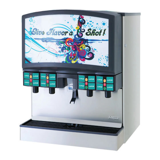
FLAVOR SELECT 30 (FS30)
ICE BEVERAGE DISPENSER
Installation and Service Manual
LANCER
6655 Lancer Blvd.
San Antonio, Texas 78219
To order parts, call
Customer Service: 800-729-1500
Warranty/Technical Support: 800-729-1550
Email: custserv@lancercorp.com
ISO 9001:2000 Quality System Certified
www.lancercorp.com
Manual PN: 28-0558/04
"Lancer" is the registered trademark of Lancer © 2008 by Lancer, all rights reserved.
7/18/08
Advertisement
Table of Contents

Related Manuals for lancer FLAVOR SELECT 30


Summary of Contents for lancer FLAVOR SELECT 30
- Page 1 San Antonio, Texas 78219 To order parts, call Customer Service: 800-729-1500 Warranty/Technical Support: 800-729-1550 Email: custserv@lancercorp.com ISO 9001:2000 Quality System Certified www.lancercorp.com Manual PN: 28-0558/04 “Lancer” is the registered trademark of Lancer © 2008 by Lancer, all rights reserved. 7/18/08...
-
Page 2: Table Of Contents
ICE BIN CLEANING - PERFORM AT START UP AND MONTHLY ..........18 CLEANING AND SANITIZING BEVERAGE COMPONENTS - BAG-IN-BOX SYSTEMS....20 ICE CHUTE CLEANING .........................20 3. HOW TO OPERATE AND ADJUST THE LANCER FS30 ................21 NORMAL OPERATION ........................21 PROGRAMMING AND SETUP SOFTWARE...................21 PURGING THE CARBONATION SYSTEM ..................23... -
Page 3: Specifications
FS30 SPECIFICATIONS DIMENSIONS WEIGHT PLAIN WATER Width: 30 in (762 mm) Without ice: 320 lbs (145 kg) Min flowing pressure: 75 PSIG Depth: 30.5 in (775 mm) With ice: 620 lbs (281 kg) (5.28 kg/cm , 5.16 BAR) Height: 40.25 in (1022 mm) Shipping: 356 lbs (161 kg) CARBONATOR WATER SUPPLY SPACE REQUIRED... -
Page 4: Fs30 Features
Dispensers using cubed ice may also use pellet ice if properly configured (contact Lancer Customer Service or your Sales Representative for more information). Lancer dispensers will not dispense shaved or flaked ice. Do not use bagged ice. Bagged ice will damage components. P.N. 28-0558/04... -
Page 5: Pre-Installation Checklist
PRE-INSTALLATION CHECKLIST BEFORE GETTING STARTED Each unit is tested under operating conditions and is thoroughly inspected before shipment. At the time of shipment, the carrier accepts responsibility for the unit. Upon receiving the unit, carefully inspect the carton for visible damage. If damage exists, have the carrier note the damage on the freight bill and file a claim with carrier. -
Page 6: Fs30 Counter Cutout
FS30 COUNTER CUTOUT 30” 15/16” 28 1/8” 23” 18 5/8” 15” 30 1/2” 11 1/2” 3“ DIAMETER OPTIONAL 1 1/2” 3“ 1 5/8” F R O N T D I S P E N S E R D R I P T R A Y 7 1/2”... -
Page 7: Safety
SAFETY AUTOMATIC AGITATION The dispenser is equipped with automatic agitation and will activate unexpectedly. Do not place hands or foreign objects in the ice storage compartment. Unplug the dispenser during servicing, cleaning, and sanitizing. To avoid personal injury, do not attempt to lift the dispenser without assistance. -
Page 8: Installation
1. INSTALLATION 1.1 SELECTING A LOCATION FOR THE DISPENSER MAKE SURE THE LOCATION MEETS THESE REQUIREMENTS: A. Access to a dedicated, grounded 20 AMP electrical outlet. B. Convenient to an open drain with access for soda, water, and syrup lines. C. - Page 9 An adapter plate is required when installing an icemaker. Contact your Sales Representative or Lancer Customer Service for more information. A bin thermostat is required in order to control the level of ice in the dispenser.
-
Page 10: Unpacking The Dispenser
1.2 UNPACKING THE DISPENSER A. Set the shipping carton upright on the floor. B. Cut band, remove. C. Open the top of the carton and remove the interior packing. D. Lift the carton up and off the dispenser. E. Remove the wood shipping base from the bottom of the dispenser. Support dispenser while removing the shipping base to prevent damage to the dispenser. -
Page 11: Installation Overview 1
1.4 INSTALLATION OVERVIEW 1 P.N. 28-0558/04... -
Page 12: Installation Overview 2
1.5 INSTALLATION OVERVIEW 2 P.N. 28-0558/04... -
Page 13: Connecting To Water Supply Lines
E. For the soda water supply line, do not exceed 50 PSI for the inlet water static pressure going into the carbonator pump. If the static water pressure exceeds 50 PSI, install a water regulator before the carbonator water inlet. NOTE: Install the water regulator (Lancer PN 18-0306) included with unit as close as possible to the water carbonator pump inlet. -
Page 14: Connecting Co2
For the soda water supply line, do not exceed 50 PSI for the inlet static water pressure going into the carbonator pump. If the static water pressure exceeds 50 PSI, install a water regulator in front of the carbonator water inlet. NOTE: Install the water regulator (Lancer PN 18-0306) as close as possible to the water carbonator pump inlet. - Page 15 D. Place the CO cylinder with the CO regulator in a serviceable location and route the CO supply line (75 PSI) to the 3/8 inch barb fitting at the front of the unit. E. Connect the syrup supply lines to the 3/8 inch barb inlet fittings at the front of the unit. Connect other end to BIB pumps.
-
Page 16: Cleaning And Sanitizing
NOTE: The cleaning and sanitizing procedures provided in this manual pertain to the Lancer FS30 dispenser. If other equipment is being cleaned, follow the guidelines established for that equipment. -
Page 17: Cleaning And Sanitizing Solutions
DO NOT Disconnect water lines when cleaning and sanitizing syrup lines, to avoid contamination. Use strong bleaches or detergents; these can discolor and corrode various materials. Use metal scrapers, sharp objects, steel wool, scouring pads, abrasives, or solvents on the dispenser. Use hot water above 140 degrees F (60 degrees C). -
Page 18: Daily Cleaning
E. Fill a cup with warm water and rinse nozzle body. F. Make certain that the nozzle o-ring is not torn or damaged. If necessary, replace damaged o-ring with Lancer PN 02-0231. G. Wet the inner surface of the nozzle housing with water and reinstall the nozzle housing by sliding it over the nozzle body and turning clockwise to lock in position. - Page 19 G. WHITE WHEEL SHROUD (PELLET ICE) G. BLACK WHEEL SHROUD (CUBED ICE) Remove the gasket which secures the shroud by Remove the dispensing wheel shroud. pulling it out. Push the front section of the shroud back. Remove the lower ice chute assembly. Pull the shroud up and out.
-
Page 20: Cleaning And Sanitizing Beverage Components - Bag-In-Box Systems
2.5 CLEANING AND SANITIZING BEVERAGE COMPONENTS - BAG-IN-BOX SYSTEMS NOTE: Extended lengths of product lines may require more time for flushing and rinsing lines than described below. A. Disconnect the syrup quick disconnect coupling from the syrup packages and connect the coupling to a bag valve removed from an empty Bag-in-Box (BIB) package. -
Page 21: How To Operate And Adjust The Lancer Fs30
Lancer representative. The Lancer FS30 has been factory preset to the settings necessary to comply with the brand/flavor version of the dispenser requested by the customer. Adjustments or upgrades should only be performed by trained personnel. For any upgrades, an upgrade kit may be purchased. - Page 22 Valves can be adjusted by scrolling through the menus (see figure above) using the UP and DOWN arrows. By pressing the ENTER button, a submenu is revealed. In the submenu, the individual valves can be adjusted to the desired configuration. B.
-
Page 23: Purging The Carbonation System
F. Activate dispensing valve to fill separator syrup tube. G. Hold a Lancer brix cup under the syrup separator and dispense water and syrup into cup for four seconds. Divide number of ounces (ml) of water in cup by four to determine water flow rate per second. -
Page 24: Carbonator Pump Modifications
L. Hold the Lancer brix cup under the syrup separator and activate valve. Check brix. M. To obtain the proper brix, use screwdriver to adjust syrup flow control. N. Once proper ratio is obtained, repeat to verify. O. Repeat for each valve. - Page 25 NOTES P.N. 28-0558/04...
-
Page 26: Troubleshooting
4. TROUBLESHOOTING TROUBLE CAUSE REMEDY 4.1 No product when switch is A. Malfunctioning switch A. Replace switch assembly. activated (switch panel is not lit). assembly. B. No power to dispenser. B. Check internal breaker and incoming power. C. Malfunctioning power supply. C. - Page 27 TROUBLE CAUSE REMEDY 4.6 Push chute, ice door opens, A. Dispenser is out of ice. A. Fill dispenser with ice. motor runs, but no ice dispenses, or ice is of poor quality. B. Agitator pin is missing or B. Replace agitator pin. damaged.
- Page 28 TROUBLE CAUSE REMEDY 4.12 Insufficient water flow (plain D. Water filtration problem. D. Service water system as water drinks). CONTINUED required. E. Defective LFCV module. E. Replace module. 4.13 Insufficient syrup flow. A. Insufficient CO2 pressure to A. Adjust CO pressure to BIB BIB pumps.
- Page 29 TROUBLE CAUSE REMEDY 4.15 Water only dispensed, no E. Stalled or inoperative BIB E. Check CO pressure and/or syrup. Or syrup only dispensed, pump. replace pump. no water. CONTINUED F. Kinked line. F. Remove kink or replace line. G. CO regulator malfunction.
- Page 30 TROUBLE CAUSE REMEDY 4.19 Water continually leaking at A. Loose water connections. A. Tighten water connections. connections. B. Flare seal washer leaks. B. Replace flare seal washer. 4.20 Circuit breaker tripping. A. Valve wire harness shorted to A. Detect short by disconnecting itself or faucet plate.
- Page 31 TROUBLE CAUSE REMEDY 4.23 BIB pump continues to A. Leak in suction line. A. Replace line. operate when bag is empty. B. Leaking o-ring on pump inlet B. Replace o-ring fitting. C. Defective syrup BIB pump. C. Replace defective pump. 4.24 BIB pump fails to restart A.
-
Page 32: Illustrations, Parts Listings, And Wiring Diagrams
5. ILLUSTRATIONS AND PARTS LISTINGS 5.1 FINAL ASSEMBLY 11 12 P.N. 28-0558/04... - Page 33 FINAL ASSEMBLY - PARTS LIST Item Part No. Description 85-14808-12 IBD, Above Counter Multi Brand Series 14800, 115V/60Hz, 8 brands / 12 flavors 85-14810-12 IBD, Above Counter Multi Brand Series 14800, 115V/60Hz, 10 brands / 12 flavors 85-14812-12 IBD, Above Counter Multi Brand Series 14800, 115V/60Hz, 12 brands / 12 flavors 85-14814-12 IBD, Above Counter Multi Brand Series 14800, 115V/60Hz, 14 brands / 12 flavors 85-14816-12...
-
Page 34: Ice Chute Assembly
ICE CHUTE ASSEMBLY 7 x2 9 x2 Item Part No. Description 05-2257/01 Chute, Upper, IC 54-0406 Chute, Printed, IBD 05-0999/01 Lever, Chute, IBD 04-0268 Scr, 6-19X.625 LG, PLSTI,HHSW/W 03-0241 Spring, Chute, IBD 12-0244 Switch, SPST, 5A, 250V, MDM 05-0359 Bushing, .123 ID x .187 OD, NYLN 05-0928/02 Trap Door, IBD 03-0113... -
Page 35: Lancer Flow Control Valve (Lfcv)
LANCER FLOW CONTROL VALVE (LFCV) LFCV Valve Assemblies Valve Assembly 82-3820 LFCV, Bonus Injector 82-3823 LFCV, 3.0 - 4.5, Syrup Assy 82-3824 LFCV, 3.0 - 4.5, Soda/Water Assy Spare Parts LFCV Spare Parts 10-0430/05 Plug Nut 02-0538 O-Ring 12-0364/04-01 Coil, LFCV... -
Page 36: Pellet Ice Assembly And Parts Listing
PELLET ICE ASSEMBLY AND PARTS LISTING LABEL FOR HOSHIZAKI ICE MAKER (TO FRONT OF DISPENSER) 5 (FOAMED ATTACH HERE TOP COVER FOR HOSHIZAKI ASSEMBLY) ATTACH HERE FOR SCOTSMAN LABEL FOR SCOTSMAN ICE MAKER (TO FRONT OF ADAPTER, DISPENSER) MECHANICAL BIN STAT Use the components listed on this page with pellet ice only. -
Page 37: Wiring Diagram - 115V/60Hz
DISPLAY 1 2 3 4 VALVE STATUS LOW HIGH SLAVE SECONDARY PRIMARY CANCEL ENTER CARB VALVE BOARD 115V (DIAGNOSTIC) POWER CARBONATOR LANCER FS16 SOLD OUT RELAY PUMP AGITATOR BOARD BALLAST ICE LINK BIN OPTION CARB CARB DOOR PROBE PUMP DOOR... -
Page 38: Plumbing Diagram With Valve Wiring
FS30 IS4-3 IS4-2 IS4-1 IS3-3 IS3-2 IS3-1 IS2-3 IS2-2 IS2-1 IS1-3 IS1-2 IS1-1 VALVE HARNESS S4-1 S3-3 S3-2 S3-1 S2-1 S2-2 S2-4 S1-2 S1-3 S3-4 USED USED DIAGRAM S4-3 S2-3 S1-1 S4-4 SODA4 S4-2 WATER2 SODA2 SODA1 S1-4 SODA3 WATER3 S3-3 S2-3 S1-3... - Page 39 NOTES P.N. 28-0558/04...
- Page 40 LANCER To order parts, call Customer Service: 800-729-1500 Warranty/Technical Support: 800-729-1550 Email: custserv@lancercorp.com www.lancercorp.com...
Need help?
Do you have a question about the FLAVOR SELECT 30 and is the answer not in the manual?
Questions and answers