Table of Contents
Advertisement
Quick Links
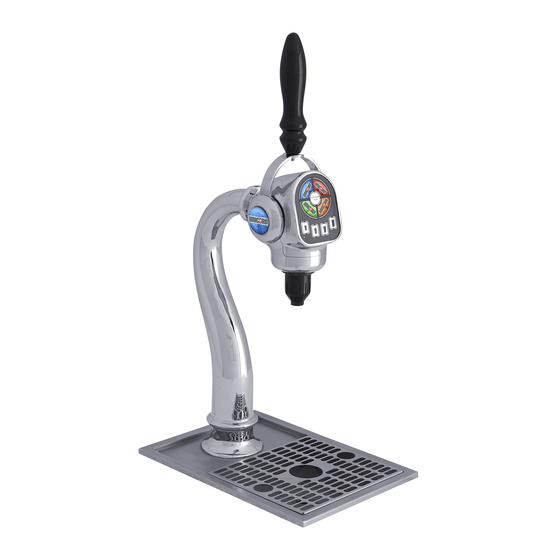
Unicorn Tower
Operation Manual
Lancer Worldwide
Technical Support/Warranty
6655 Lancer Blvd.
800-729-1550
San Antonio, Texas 78219
custserv@lancerworldwide.com
310
800-729-1500
lancerworldwide.com
PN: 28-0883 Rev: 05-6
"Lancer" is the registered trademark of Lancer © 2021 by Lancer, all rights reserved.
Advertisement
Table of Contents

Related Manuals for lancer Unicorn Tower


Summary of Contents for lancer Unicorn Tower
- Page 1 Unicorn Tower Operation Manual Lancer Worldwide Technical Support/Warranty 6655 Lancer Blvd. 800-729-1550 San Antonio, Texas 78219 custserv@lancerworldwide.com 800-729-1500 lancerworldwide.com PN: 28-0883 Rev: 05-6 “Lancer” is the registered trademark of Lancer © 2021 by Lancer, all rights reserved.
-
Page 2: Table Of Contents
TABLE OF CONTENTS ABOUT THIS MANUAL BEFORE GETTING STARTED This booklet is an integral and essential part of the product and Each unit is tested under operating conditions and is thoroughly should be handed over to the operator after the installation and inspected before shipment. -
Page 3: Important Safety Instructions
IMPORTANT SAFETY INSTRUCTIONS ! Intended Use F Power • The dispenser is for indoor use only • Follow all local electrical codes when making connections. • This appliance is intended to be used in commercial applications such as restaurants or similar. •... -
Page 4: Specifications And Features
SPECIFICATIONS AND FEATURES Multi-brand Tower Specifications A. Tower B. Handle C. Keypad/Face Plate D. Nozzle E. Drip Tray/Cup Rest F. Junction Box DIMENSIONS PLAIN WATER SUPPLY Width: 4.95 inches (126 mm) Min Flowing Pressure: 40 PSIG (0.276 MPA) Depth: 11.1 inches (282 mm) Max Pressure: 110 PSIG (0.756 MPA) Height: 25.4 inches (645 mm) SYRUP SUPPLY... -
Page 5: Single Brand Tower Specifications
Single Brand Tower w/ ADA Specifications A. Tower B. Handle C. Keypad/Face Plate D. Nozzle E. Drip Tray/Cup Rest F. ADA G. Junction Box DIMENSIONS PLAIN WATER SUPPLY Width: 4.95 inches (126 mm) Min Flowing Pressure: 40 PSIG (0.276 MPA) Depth: 11.1 inches (282 mm) Max Pressure: 110 PSIG (0.756 MPA) Height: 25.4 inches (645 mm) -
Page 6: General System Overview - Multibrand Tower
General Systems Overview - Multi-brand Tower Syrup Line Line Plain Water Line Drain Line Electrical Carb Water Line Carb Water Return A. Water Source B. CO Source C. High Pressure CO Regulator D. Electrical Outlet E. Tower (Dispenser) F. Junction Box G. -
Page 7: Pre-Installation Checklist
Do you have enough space to Drill Oetiker Clamp Fittings install the dispenser and junction box? BIB SYSTEM: Water Booster (Lancer PN: 82-3401 or MC-163172 Is countertop level? BIB Rack Water Regulator (recommended) Is countertop at least 1 inch BIB Syrup Boxes... -
Page 8: Installation
INSTALLATION Read This Manual This manual was developed by Lancer Worldwide as a reference guide for the owner/operator and installer of this dispenser. Please read this manual before installation and operation of this dispenser. Please see pages 16-18 for troubleshooting or service assistance. If the service cannot be corrected please call your Service Agent or Lancer Customer Service. -
Page 9: Tower Installation
Route ribbon cable, harness, and syrup/water lines through the the tower connection nut provided, then thread the nut If Unicorn Tower being installed is a Single Brand onto the tower and tighten to secure to counter. Tower with an ADA Panel, skip to next section. -
Page 10: Junction Box Installation
Junction Box Installation NOTE Align the Junction Box with the Mounting Bracket, then slide box through bracket to secure to counter. Tower harnesses and syrup/water lines are all 36 inches in length. Placement of the Junction Box must be under the counter and within 2 feet (24 inches) of the Tower assembly. - Page 11 Plumbing Line Connections NOTE Route appropriate tubing from the water outlet at remote chiller to the water inlet at junction box. Repeat for return Unit is designed to be supported by a remote chiller line. system or remote ice cooled system. Please see the manufacturer’s specifications and instructions for installation.
-
Page 12: Adjust Water Flow Rate & Syrup/Water Ratio
Use a screwdriver to adjust if needed. Close syrup shut-off at mounting block for syrup brands Using a Lancer ratio cup verify water flow rate (14 oz. in 8 sec.). Use a screwdriver to adjust if needed. Increase Decrease A. -
Page 13: Programming And Configuration
PROGRAMMING AND CONFIGURATION Programming Overview NOTE The following sections are for Multi-brand units with Volumetric or LFCVs ONLY. Does not apply for Single Brand units. A. Brand 1 B. Brand 2 C. Brand 3 D. Brand 4 E. Water Button F. -
Page 14: Purge Mode
Purge Mode NOTE Press and hold Water Button, to dispense water. Press and hold a Brand Button, to dispense brand syrup Purge Mode allows independent purging of water or only syrup without shutting off the back block. NOTE If unit is in Idle Mode with no Active Brand selected, and The unit will default to Idle Mode automatically, if: has not been dispensed since unit was powered on, the •... -
Page 15: Cleaning And Sanitizing
General Information • Lancer equipment (new or reconditioned) is shipped from the factory cleaned and sanitized in accordance with NSF guidelines. The operator of the equipment must provide continuous maintenance as required by this manual and/or state and local health department guidelines to ensure proper operation and sanitation requirements are maintained. -
Page 16: Weekly Cleaning And Sanitizing
Weekly Cleaning and Sanitizing Disconnect power to the unit. Mix appropriate amount of cleaning and sanitizing solution in a clean container. Remove nozzle by twisting counterclockwise and pulling down, then submerge the nozzle in the cleaning solution and wipe clean. Submerge the nozzle in the nozzle in the seperate sanitizing solution and set aside to air dry A. -
Page 17: Troubleshooting
TROUBLESHOOTING TROUBLE CAUSE REMEDY Water leakage around nozzle. O-ring is damaged or missing. Replace o-ring. Miscellaneous leakage. Gap between parts. Tighten appropriate retaining screws Damaged or improperly installed o-rings. Replace or adjust appropriate o-rings Insufficient water flow. Insufficient incoming supply water Verify incoming supply water pressure is a pressure. - Page 18 TROUBLE CAUSE REMEDY Water only dispensed; no Water or syrup shutoff on mounting block Open shutoff fully. syrup; or syrup only not fully open. Remove valve from mounting block, open dispensed, no water Improper or inadequate water or syrup shutoffs slightly and check water and flow.
- Page 19 TROUBLE CAUSE REMEDY Circuit breaker tripping. Valve wire harness shorted to itself or to Detect short by disconnecting input fasten faucet plate. to keylock and single pin connector. Restore power if breaker doesn’t trip. PCB is bad. Then valve wire harness is shorted. If OK, Secondary wire harness is bad.
-
Page 20: Illustrations And Part Listings
ILLUSTRATIONS AND PART LISTINGS Electronics Board - LFCV Item Part No. Description 52-3732 Harness, Main Controller, Unicorn 52-3344 Harness, LFCV, Thru-Central Valve, Unicorn 52-3358 Harness, Bypass, Unicorn 64-5048 PCB Assembly, Main Board, Unicorn 05-1678 Standoff, PCB, Rev Locking 52-3734 Harness, ADA Switch to PCB, Single Brand... -
Page 21: Electronics Board - Vv
Electronics Board - VV Item Part No. Description 52-3381 Harness, Water Module, VV, Recirc, Unicorn 52-3359 Harness, Solenoid, KIP, VV, Unicorn 52-3360 Harness, Solenoids VV, Unicorn 52-3358 Harness, Bypass, Unicorn 64-5048/02 PCB Assembly, Main Board, Unicorn 05-1678 Standoff, PCB, Rev Locking... -
Page 22: Nozzle Assembly - Lfcv
Item Part No. Description 64-5057 PCB Assembly, Touch Pad, Unicorn, w/ Portion Control 05-3475 Single Brand Blank Plate (Used only with Single Brand Unicorn Tower, 85-3161R-12-2204) 17-0647/01 Solenoid, 24 VDC, 1/8 NPT, 2 WNC 05-2971 Elbow, Quick Connect, 1/4 x 1/8 05-1736... -
Page 23: Nozzle Assembly - Vv
Nozzle Assembly - VV Item Part No. Description 02-0371 Washer, Flow, 1.5, Vol Valve 02-0089 O-Ring, 2-012, 97-0999 02-0126 O-Ring, 2-109, 97-0999 01-2762 Fittingg, Soda Outlet, Unicorn 02-0005 O-Ring, 2-010, 97-0999 02-0214 O-Ring, 2-008, 97-0999 05-2929 Fitting, Inlet, Nozzle, Syrup 04-1639 Screw, 4-20X.250 IN, PH, Phillips, Plastitie, 18-8 Ss... -
Page 24: Lfcv Spare Parts
LFCV Spare Parts Item Part No. Description 01-2884 Fitting, JG, 3/8 X 1/4, Reducer, S/Fit 01-2806 JG Bulkhead Connector, 3/8 S/Fit X 3/8 S/Fit 19-0267/02 Valve Assembly, LFCV, 2.0 Soda, Gray, S 05-1385 Elbow, .5 Dole X .2 Barb, Pls 02-0089 O-Ring, 2-012, 97-0999 19-0266/02... - Page 25 Water Valve, Volumetric Valve Spare Parts Item Part No. Description 05-1385 Elbow, .5 Dole X .2 Barb, PLS 02-0089 O-Ring, 2-012, 97-0999 19-0399 Water Module, Vol,1.5 - 3.0 05-0967 Retainer, Sol Vlv, Ball Vlv, Premia 02-0005 O-Ring , 2 -010, 97-0999 05-1386 Elbow, .375 Dole X .2 Barb, PLS 19-0398...
-
Page 26: Misc. Spare Parts
Item Part No. Description 64-5057 PCB Assembly, Touch Pad, Unicorn, W/Portion Control 01-2757 Fitting, Wye, .12I d, Unicorn 01-2806 Jg Bulkhead Connector, 3/8 S/Fit X 3/8 S/Fit, 79000217 05-3475 Single Brand Blank Plate (Used only with Single Brand Unicorn Tower, 85-3161R-12-2204) -
Page 27: Wiring Diagram - Lfcv
Wiring Diagram - LFCV... -
Page 28: Wiring Diagram - Vv
Wiring Diagram - VV... -
Page 29: Counter Cutout
Counter Cutout (Not to Scale) - Page 30 Lancer Worldwide 800-729-1500 Technical Support/Warranty: 800-729-1550 custserv@lancerworldwide.com lancerworldwide.com...
Need help?
Do you have a question about the Unicorn Tower and is the answer not in the manual?
Questions and answers