Table of Contents
Advertisement
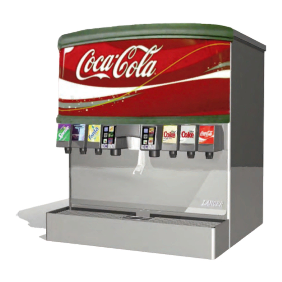
22", 30" BEVARIETY™ ACIB ICE
BEVERAgE DISPENSERS
MODELS MCY-22 & MCY-30
Installation and Service Manual
PN 28-0724/02
6/16/2009
LANCER
6655 Lancer Blvd.
San Antonio, Texas 78219
To order parts, call
Customer Service: 800-729-1500
Warranty/Technical Support: 800-729-1550
Email: custserv@lancercorp.com
www.lancercorp.com
ISO 9001:2000 Quality System Certified
"Lancer" is the registered trademark of Lancer © 2009 by Lancer, all rights reserved.
Advertisement
Table of Contents
Troubleshooting


Need help?
Do you have a question about the BEVARIETY MCY-22 and is the answer not in the manual?
Questions and answers