Rockwell Automation Allen-Bradley AADvance T9110 System Build Manual
Hide thumbs
Also See for Allen-Bradley AADvance T9110:
- Solutions handbook (165 pages) ,
- Troubleshooting and maintenance manual (96 pages)

Related Manuals for Rockwell Automation Allen-Bradley AADvance T9110


Summary of Contents for Rockwell Automation Allen-Bradley AADvance T9110
- Page 1 AADvance Controller Catalog Numbers T9110, T9300, T9310, T9401/2, T9431/2, T9451, T9481/2 System Build Manual Original Instructions...
- Page 2 If this equipment is used in a manner not specified by the manufacturer, the protection provided by the equipment may be impaired. In no event will Rockwell Automation, Inc. be responsible or liable for indirect or consequential damages resulting from the use or application of this equipment.
-
Page 3: Preface
About This Publication validate the operation of your system. In no event will Rockwell Automation be responsible or liable for indirect or consequential damages resulting from the use or application of this equipment. The examples given in this manual are included solely for illustrative purposes. -
Page 4: Download Firmware, Aop, Eds, And Other Files
For the latest information about this product review the Product Notifications and Technical Notes issued by technical support. Product Notifications and product support are available at the Rockwell Automation Support Center at rok.auto/knowledgebase. At the Search Knowledgebase tab select the option "By Product" then scroll down and select the ICS Triplex®... - Page 5 Updated suggested range of values Removed row for T9085. Added row for T9090. Software on page 130 Removed rows for T9901...T9906. N on page 143 Removed NFPA 87. proof test on page 144 Updated definition. Rockwell Automation Publication ICSTT-RM448M-EN-P - February 2021...
-
Page 6: Additional Resources
Controller. Industrial Automation Wiring and Grounding Guidelines, publication 1770-4.1 Provides general guidelines for installing a Rockwell Automation industrial system. Product Certifications website, rok.auto/certifications. Provides declarations of conformity, certificates, and other certification details. You can view or download publications at rok.auto/literature. -
Page 7: Table Of Contents
Processor Base Unit......... . 33 Rockwell Automation Publication ICSTT-RM448M-EN-P - February 2021... - Page 8 Specify software requirements ........66 Design Considerations for Maintenance Activities ....66 Rockwell Automation Publication ICSTT-RM448M-EN-P - February 2021...
- Page 9 Controller IP Address ........120 Rockwell Automation Publication ICSTT-RM448M-EN-P - February 2021...
- Page 10 Glossary ........... . 137 Rockwell Automation Publication ICSTT-RM448M-EN-P - February 2021...
-
Page 11: The Aadvance System
A system is built from an approved range of modules and assemblies. Rockwell Automation Publication ICSTT-RM448M-EN-P - February 2021... - Page 12 Chapter 1 The AADvance System Notes: Rockwell Automation Publication ICSTT-RM448M-EN-P - February 2021...
-
Page 13: The Aadvance Safety Controller
A system can have just one or more controllers, a combination of I/O modules, power sources, communications networks and computers. It can operate as a stand-alone system or as a distributed node of a larger control system. Rockwell Automation Publication ICSTT-RM448M-EN-P - February 2021... - Page 14 They can be mounted onto DIN rails in a cabinet or directly mounted onto a wall in a control room. Forced air cooling or special environmental control Rockwell Automation Publication ICSTT-RM448M-EN-P - February 2021...
-
Page 15: Safety Features
SIL 3 safety related system requirements. The system has comprehensive built-in redundant capabilities that improve system availability. The AADvance safety system features are: • Easily transformed from a simplex non-safety system to a fault tolerant safety related system. Rockwell Automation Publication ICSTT-RM448M-EN-P - February 2021... -
Page 16: Safety Configurations
SIL 3 dual or triple processor architectures • SIL 3 high demand applications where the required safe state is greater than 4 mA, when fitted with dual analogue output modules (A ‘safe state’ Rockwell Automation Publication ICSTT-RM448M-EN-P - February 2021... -
Page 17: Safety System Certification
The controller processing scan times listed in the table are taken from a test system which used only production modules. The tests which were used to measure the scan times did not measure the effects of logic complexity and communications loading. Rockwell Automation Publication ICSTT-RM448M-EN-P - February 2021... - Page 18 Maximum throughput time = 2 x Scan time + 13 ms EXAMPLE: An example configuration scan time: System configuration includes T9432 Analogue input simplex modules x 30 and T9451 Digital output simplex modules x 18. Rockwell Automation Publication ICSTT-RM448M-EN-P - February 2021...
-
Page 19: System Installation Environment
The AADvance system has been investigated to United States National Standard (s) UL508, 17th Edition and Canadian National Standard (s) C22.2 No 142, 1st Edition. The investigation covers the following modules and provides Rockwell Automation Publication ICSTT-RM448M-EN-P - February 2021... -
Page 20: Installation Requirements For Non-Hazardous Environment
T9851 Digital Output Termination Assembly, Simplex and T9852 Digital Output Termination Assembly, Dual • T9892 Digital Output Termination Assembly, Dual • T9881 Analogue Output Termination Assembly, Simplex • T9882 Analogue Output Termination Assembly, Dual. Rockwell Automation Publication ICSTT-RM448M-EN-P - February 2021... -
Page 21: Installation Requirements For Hazardous Environment
Additionally the AADvance controller is approved under the IECEx certification scheme. The certificate number is IECEx UL 12.0032X. Installation Requirements To comply with the standards the following conditions must be applied to the installation: Rockwell Automation Publication ICSTT-RM448M-EN-P - February 2021... -
Page 22: File Number E251761
CSA C22.2 No 142-M1987, Process Control equipment, Edition 1 - Revision date 1990-09-01. Products Covered The products investigated and approved: Programmable Logic Controllers Models: • T9110 Processor Module • T9401/2 Digital Input Module Rockwell Automation Publication ICSTT-RM448M-EN-P - February 2021... -
Page 23: Certifications For Safety System Applications In Hazardous
ATEX certificate, publication 9000-CT003. IECEx UL Certificate Refer to AADvance Series T9000 Programmable Control and Safety System - IECEx certificate, publication 9000-CT006. Module Label The following label information must be attached to each module. Rockwell Automation Publication ICSTT-RM448M-EN-P - February 2021... -
Page 24: Kcc-Emc Registration
The AADvance Workbench software and AADvance-Trusted SIS Workstation software are compliant with the IEC-61131 industrial standard and have several powerful features: • the regulation of the flow of control decisions for an interacting distributed control system Rockwell Automation Publication ICSTT-RM448M-EN-P - February 2021... -
Page 25: Operating Systems
Operating Systems For information about supported operating systems and other software product version support, refer to product release notes from the Product Compatibility and Download Center (PCDC): rok.auto/pcdc. Rockwell Automation Publication ICSTT-RM448M-EN-P - February 2021... -
Page 26: Importing And Exporting Data
Main Components An AADvance controller is built from durable processor and I/O modules and assemblies designed to IEC 61508 standards for safety systems and runs the AADvance Workbench software or AADvance-Trusted SIS Workstation Rockwell Automation Publication ICSTT-RM448M-EN-P - February 2021... -
Page 27: Physical Features
0.1 g in 3 axes Endurance 10 Hz to 150 Hz Acceleration 0.5 g in 3 axes Shock 15 g peak, 11 ms duration, ½ sine Altitude Operating 0 to 2,000 m (0 to 6,600 ft.) Rockwell Automation Publication ICSTT-RM448M-EN-P - February 2021... -
Page 28: Product Dimensions
I/O base unit mated with the processor base unit. I/O modules are installed on the base unit and a termination assembly plugged into the I/O base unit. Rockwell Automation Publication ICSTT-RM448M-EN-P - February 2021... - Page 29 Adding the depth of a module (118 mm) to the depth of the base unit gives the overall depth of the controller assembly at 136 mm. Rockwell Automation Publication ICSTT-RM448M-EN-P - February 2021...
-
Page 30: Compact Module Design
Modules are retained by a locking screw which is easy to access from the front. Rockwell Automation Publication ICSTT-RM448M-EN-P - February 2021... -
Page 31: Module Polarization Keying
Sockets on the rear end plate align and mate with coding pins found on the termination assembly. The alignment of the sockets and pins make sure that only the matched I/O modules and termination assemblies can be mated. Rockwell Automation Publication ICSTT-RM448M-EN-P - February 2021... -
Page 32: Module Locking Mechanism
The locking mechanism is in the form of a clamp screw, which can be seen on the front panel of the module and engaged by a quarter turn of a flat blade screwdriver. The module senses the locking mechanism position and Rockwell Automation Publication ICSTT-RM448M-EN-P - February 2021... -
Page 33: Field Wiring
This illustration shows field wiring connections at the termination assemblies. Figure 5 - Field Wiring Connections NOTE The recommended torque for termination assembly screw connectors is 5 Nm. Processor Base Unit A processor base unit holds up to three processor modules: Rockwell Automation Publication ICSTT-RM448M-EN-P - February 2021... -
Page 34: External Ethernet, Serial Data And Power Connections
Chapter 2 The AADvance Safety Controller External Ethernet, Serial Data and Power Connections The processor base unit external connections are: Rockwell Automation Publication ICSTT-RM448M-EN-P - February 2021... -
Page 35: Serial Communications Ports
The T9110 processor module has a back-up battery that powers its internal Real Time Clock (RTC) and a part of the volatile memory (RAM). The battery only supplies power when the processor module is no longer powered from the Rockwell Automation Publication ICSTT-RM448M-EN-P - February 2021... - Page 36 AADvance-Trusted SIS Workstation software. Battery Location The battery is supplied separately and inserted into a slot behind a removable cover on the front panel of the processor module. The battery position is shown in the illustration: Rockwell Automation Publication ICSTT-RM448M-EN-P - February 2021...
-
Page 37: Processor Maintenance Socket
CAUTION: K1 is for maintenance only. When AADvance is installed in a hazardous location power must be disconnected or the area known to be free of ignitable concentrations of flammable gases or vapours when using this socket. Rockwell Automation Publication ICSTT-RM448M-EN-P - February 2021... -
Page 38: I/O Base Unit
L’ a limentation doit être coupée ou la zone exempte de concentrations de gaz ou de vapeurs inflammables lorsqu’il est utilisé. I/O Base Unit An I/O base unit holds up to three I/O modules: Rockwell Automation Publication ICSTT-RM448M-EN-P - February 2021... - Page 39 Chapter 2 The AADvance Safety Controller Rockwell Automation Publication ICSTT-RM448M-EN-P - February 2021...
-
Page 40: Termination Assemblies
The field wiring connectors are located to the left, the fuses have a cover (shown open) and the module sockets are to the right. Each fuse cover has a label that identifies the fuse numbers. Figure 7 - Single Termination Assembly Rockwell Automation Publication ICSTT-RM448M-EN-P - February 2021... - Page 41 T9892 has a separate connector for the field power input voltage connections (the left most terminal block shown below). It also has additional fusing to give extra protection against field faults. Rockwell Automation Publication ICSTT-RM448M-EN-P - February 2021...
-
Page 42: Backplane Electrical Ratings
TAs and modules. They are not operating values so don't use them to calculate the controller power consumption or heat dissipation values. Refer to the separate topics on estimating Heat Dissipation and Power Consumption. Rockwell Automation Publication ICSTT-RM448M-EN-P - February 2021... -
Page 43: Expansion Cable
T9832 18-32 0-24 T9833 18-32 0-24 T9851 18-32 T9852 18-32 T9892 18-32 T9881 18-32 0-24 T9882 18-32 0-24 Expansion Cable This is used to add extra rows of I/O base units and modules. Rockwell Automation Publication ICSTT-RM448M-EN-P - February 2021... -
Page 44: Technical Features
Each I/O module has a dedicated response line which returns to the processor. The unique response line for each I/O module supplies an unambiguous identification of the source of the I/O data and assists with fault containment. Rockwell Automation Publication ICSTT-RM448M-EN-P - February 2021... -
Page 45: Internal Diagnostics And Fault Reset
Faults in the I/O modules are latched. To clear them a fault reset signal is sent from the processor module by pressing the Fault Reset button on Rockwell Automation Publication ICSTT-RM448M-EN-P - February 2021... -
Page 46: Remote Fault Reset
O modules. To put the new modules on-line and make the changes to the system fully operational, the hardware configuration in the AADvance Workbench software or AADvance-Trusted SIS Workstation software must be updated by an on-line update. Rockwell Automation Publication ICSTT-RM448M-EN-P - February 2021... -
Page 47: Hot Swap I/O For Business Critical Channels
Recovery Mode at the same time a single ControlFLASH update will be applied to all the modules Update procedure: • Run the ControlFLASH program • Select the type of module from the list Rockwell Automation Publication ICSTT-RM448M-EN-P - February 2021... -
Page 48: Ethernet Communication Protocols
2010 Always available Rockwell Automation) 2222 When configured CIP produce and consume I/Os When at least one P2P 5000 subnet is active on a Peer-to-peer controller 44818 Always available CIP produce and consume Rockwell Automation Publication ICSTT-RM448M-EN-P - February 2021... -
Page 49: Application Development
(program organization unit) and its operations, and the interactions between modules to form the complete application. This modular construction can help future use of code units. Engineers can debug their own modules independently from each other. Rockwell Automation Publication ICSTT-RM448M-EN-P - February 2021... -
Page 50: Support For Variable Types
KEY connector on the T9100 processor base unit before you can download and make changes to an application. The program enable key is supplied with the processor base unit and is fitted as shown. Rockwell Automation Publication ICSTT-RM448M-EN-P - February 2021... -
Page 51: Aids To Software Development
Development stage of development, correcting or prompting the user with the correct use of the language. There is also extensive on-line help, which includes a cross- referenced explanation of the IEC 61131-3 standard. Rockwell Automation Publication ICSTT-RM448M-EN-P - February 2021... - Page 52 Chapter 3 Application Development Notes: Rockwell Automation Publication ICSTT-RM448M-EN-P - February 2021...
-
Page 53: Before You Begin
The enclosure must also be able to handle the heat dissipated by the modules and other components/devices included in the same enclosure. Rockwell Automation Publication ICSTT-RM448M-EN-P - February 2021... -
Page 54: Maximum Enclosure Air Temperature
• Pollution Degree 3: Conductive pollution occurs or dry non-conductive pollution occurs which becomes conductive due to condensation which is to be expected. Rockwell Automation Publication ICSTT-RM448M-EN-P - February 2021... -
Page 55: Enclosure Requirements For A Hazardous Environment - Class I
• Les dispositifs concernés doivent être installés verticalement uniquement. WARNING: EXPLOSION HAZARD Do not connect or disconnect equipment while the circuit is live or unless the area is known to be free of ignitable concentrations or equivalent. Rockwell Automation Publication ICSTT-RM448M-EN-P - February 2021... -
Page 56: Controller Mounting
Space below, to let modules fit and to be able to hold a module during removal. • Space to the right of the last base unit in the row, to move an I/O base unit during assembly or if you are installing a new base unit. Rockwell Automation Publication ICSTT-RM448M-EN-P - February 2021... - Page 57 88 mm MIN 57 mm 7 mm HOLE ‘A’ 171 mm MIN 256 mm Minimum Clearance Minimum 50 mm Clearance Minimum Clearance 19 mm 50 mm 30 mm DIMENSION ‘X’ MIN 69 mm Rockwell Automation Publication ICSTT-RM448M-EN-P - February 2021...
-
Page 58: Base Units Rows And Expansion Cables
I/O base units to install extra rows of I/ O base units. Base units are secured in place by top and bottom clips that are inserted into the slots on each base unit. Rockwell Automation Publication ICSTT-RM448M-EN-P - February 2021... - Page 59 01 to 24, the left most position being slot 01. Any individual module position within the controller can thus be uniquely identified by the combination of its bus and slot numbers, for example 1-01. Rockwell Automation Publication ICSTT-RM448M-EN-P - February 2021...
-
Page 60: Adding Field Cable Management
Each controller also requires an external field power source for the field loops. WARNING: A controller system must be installed with a power network that is designed to meet over voltage Category II Rockwell Automation Publication ICSTT-RM448M-EN-P - February 2021... -
Page 61: Power Supply And Power Distribution Requirements
An over current fault in the controller must not cause the system to lose power. Consequently, the power sources must be able to supply the peak current to open any over current protection devices (such as fuses) without failing. Rockwell Automation Publication ICSTT-RM448M-EN-P - February 2021... -
Page 62: Power Arrangements For Field Devices
Power Distribution Protection The power distribution circuit for each field input and for each output module must be protected, externally to the controller. Rockwell Automation recommend that power distribution must meet national and local panel wiring protection standards. -
Page 63: System Design Considerations For Heat Dissipation And Cooling
Maximum Air Temperature The maximum air temperature rating in an enclosure where AADvance modules are installed to support predictable operation is 70 °C (158 ° F). Rockwell Automation Publication ICSTT-RM448M-EN-P - February 2021... -
Page 64: Estimate Heat Dissipation
Maximum Channel Output Current OR Field Voltage/(2 x Load Resistance) Estimate AADvance Use the following table to make an estimate of the weight of your controller. Controller Weight Rockwell Automation Publication ICSTT-RM448M-EN-P - February 2021... -
Page 65: Estimating Center Of Gravity Information
The shield ground will usually be connected to the AC safety ground; or, more rarely, to the instrument ground. In practice, the continuity of the shield connections will be more important than the goodness of the ground connection provided. Rockwell Automation Publication ICSTT-RM448M-EN-P - February 2021... -
Page 66: Specify Software Requirements
The design of the controller installation should make the following provisions: • Clear access to remove and install modules, termination assemblies, base units and security dongle (Program Enable key). Repair of controller modules will be by module replacement. Rockwell Automation Publication ICSTT-RM448M-EN-P - February 2021... - Page 67 Chapter 4 Before You Begin A way for plant operations personnel to inspect the status LEDs on each module. The status LEDs report faults. Rockwell Automation Publication ICSTT-RM448M-EN-P - February 2021...
- Page 68 Chapter 4 Before You Begin Clear access to examine, remove and install fuses located on the termination assemblies. Rockwell Automation Publication ICSTT-RM448M-EN-P - February 2021...
- Page 69 In addition, it may be appropriate to make the following provisions: • A lock on the door of the enclosure, to deter unauthorized access and possible unofficial modifications. • Lighting. • Utility sockets. Rockwell Automation Publication ICSTT-RM448M-EN-P - February 2021...
-
Page 70: Connecting The Aadvance Controller To The Network
For each network connection, insert the RJ45 modular plug on the cable into the appropriate socket. • Make sure the length of the cable does not exceed 100m (328 ft). Refer to the illustration for an example. Rockwell Automation Publication ICSTT-RM448M-EN-P - February 2021... - Page 71 Chapter 4 Before You Begin Rockwell Automation Publication ICSTT-RM448M-EN-P - February 2021...
- Page 72 Chapter 4 Before You Begin Notes: Rockwell Automation Publication ICSTT-RM448M-EN-P - February 2021...
-
Page 73: Install The Aadvance System
• If any part of the delivered components has been damaged during shipping, notify the carrier and Rockwell Automation immediately. Damaged goods must be returned Rockwell Automation for repair or replacement (see Warranty and Returns instructions with delivery documentation). CAUTION: Handling Modules Stored at Extreme Temperatures: It is recommended that modules removed from storage should be allowed to normalize their temperature before installation. - Page 74 (below the base unit) to the left. 3. Mount each T9300 I/O base unit • Place a T9300 I/O base unit onto the DIN rails to the right of the T9100 processor base unit. Rockwell Automation Publication ICSTT-RM448M-EN-P - February 2021...
-
Page 75: Fitting Termination Assemblies
• Install two end stops onto the upper DIN rail, one at each end of the assembly. Fitting Termination Assemblies Figure 16 - How to Fit Termination Assemblies 1. To fit termination assemblies do the following: Rockwell Automation Publication ICSTT-RM448M-EN-P - February 2021... - Page 76 • Examine a coding peg (fitted) and identify the index recess on the hexagonal flange. • Refer to the following table and verify each coding peg is fitted so its index recess is adjacent to the relevant numbered position. Rockwell Automation Publication ICSTT-RM448M-EN-P - February 2021...
-
Page 77: Allocations Of Coding Pegs
Place the lug below the second nut on the ground stud, between two washers, and use two 10mm wrenches to tighten the nuts to a torque of 1.2 Nm to 2 Nm (0.88 lb./ft. to 1.48 lb./ft.). Rockwell Automation Publication ICSTT-RM448M-EN-P - February 2021... -
Page 78: Connect The 24 Vdc System Power To An Aadvance Controller
The processor base unit has a link between the +24 Vdc connections to the center terminal of each connector PWR-1 and PWR-2. This link may be useful to connect the +24 Vdc supply to further devices: Rockwell Automation Publication ICSTT-RM448M-EN-P - February 2021... -
Page 79: Procedure To Connect Serial Communications Cabling
Make sure that PWR-1 and PWR-2 are supplied from independent 24 Vdc sources. Procedure to Connect Serial The serial ports (S1-1 and S1-2; S2-1 and S2-2; S3-1 and S3-2) support the following signal modes depending on use: Communications Cabling Rockwell Automation Publication ICSTT-RM448M-EN-P - February 2021... - Page 80 Make sure the length of the cable does not exceed 1,200 m (3,900 ft.). Serial Communications Illustration Terminal Function Description (4-wire) Function Description (2-wire) TRX_A Receive data A (inverting) Transmit/receive data A (inverting) Transmit/receive data B (non- TRX_B Receive data B (non-inverting) inverting) Rockwell Automation Publication ICSTT-RM448M-EN-P - February 2021...
-
Page 81: Connecting Modbus Slave Devices To Serial Ports
Connect a Slave Device, Full Duplex You can use a full duplex serial connection to connect one MODBUS Slave device to the AADvance controller. To make the physical connection, do the following: Rockwell Automation Publication ICSTT-RM448M-EN-P - February 2021... -
Page 82: Connect Multiple Slave Devices, Full Duplex
5. Insert the connector into the T9100 processor base unit. Connect Multiple Slave Devices, Full Duplex You can use a full duplex serial connection to connect multiple MODBUS Slave devices to the AADvance controller. To make the physical connection, do the following: Rockwell Automation Publication ICSTT-RM448M-EN-P - February 2021... -
Page 83: Connect A Slave Device, Half Duplex
Connect a Slave Device, Half Duplex You can use a half duplex serial connection to connect a single MODBUS Slave device to the AADvance controller. To make the physical connection, do the following: Rockwell Automation Publication ICSTT-RM448M-EN-P - February 2021... -
Page 84: Connect Multiple Slave Devices, Half Duplex
5. Insert the connector into the T9100 processor base unit. Connect Multiple Slave Devices, Half Duplex You can use a half duplex serial connection to connect multiple MODBUS Slave devices to the AADvance controller. To make the physical connection, do the following: Rockwell Automation Publication ICSTT-RM448M-EN-P - February 2021... -
Page 85: System Security
Ethernet networks which are frequently part of a larger corporate network and can expose the system to accidental or malicious infection or attack. These steps help prevent such issues: • Consider network and computer security, for example: Rockwell Automation Publication ICSTT-RM448M-EN-P - February 2021... -
Page 86: Connecting Field Wiring
0.5 Nm (0.37 ft. lb.) to the terminal screws. Digital Input Field Loop Circuits Recommended Field Loop Circuits This section contains recommended field loop circuits for line monitoring digital inputs used in Emergency Shutdown or Fire & Gas applications. Rockwell Automation Publication ICSTT-RM448M-EN-P - February 2021... - Page 87 R1 = 15K 1%, 1W (maximum power dissipated is 47mW at 26.4V) R2 = 3K9 1%, 1W (maximum power dissipated is 182mW at 26.4V) Suggested range of values for both of the above circuits are as follows: Rockwell Automation Publication ICSTT-RM448M-EN-P - February 2021...
- Page 88 The values verify that a line fault will be declared before it becomes possible for a false declaration of On and Off states due to a combination of resistor value drift and loop voltage variation. Rockwell Automation Publication ICSTT-RM448M-EN-P - February 2021...
- Page 89 For further information, please refer to application note AN-T90001 Field Loop Configuration, which is located in the Rockwell Automation Knowledgebase Support Center. This also includes advice for fire detectors which are not simple volt free contacts. Digital Input Slew Tolerance...
- Page 90 Chapter 5 Install the AADvance System Connections to T9801 Non-isolated Digital Input TA — 16 Channel Simplex • Apply a minimum tightening torque of 0.5 Nm (0.37 ft. lb.) to the terminal screws. Rockwell Automation Publication ICSTT-RM448M-EN-P - February 2021...
-
Page 91: Analogue Input Field Loop Circuits
These circuits can be used for simplex, dual and triple configurations of analogue input modules. Fit a fuse (as shown) in each circuit to protect the field wiring. The recommended field loop circuits for analogue inputs are as shown below. Rockwell Automation Publication ICSTT-RM448M-EN-P - February 2021... - Page 92 Chapter 5 Install the AADvance System Field Loop Circuit for 2-Wire Analogue Input Figure 17 - Wire Analogue Input Field Loop Rockwell Automation Publication ICSTT-RM448M-EN-P - February 2021...
- Page 93 Chapter 5 Install the AADvance System Field Loop Circuit for 3-Wire Analogue Input Figure 18 - Wire Analogue Input Field Loop Rockwell Automation Publication ICSTT-RM448M-EN-P - February 2021...
- Page 94 Solutions Handbook. Accordingly it may be necessary to condition the input signal such as by filtering, sensor slew rate configuration or by appropriate choice of process safety time. Rockwell Automation Publication ICSTT-RM448M-EN-P - February 2021...
- Page 95 Chapter 5 Install the AADvance System Connections to T9831 Non-isolated Analogue Input TA — 16 Channel Simplex • Apply a minimum tightening torque of 0.5 Nm (0.37 ft. lb.) to the terminal screws. Rockwell Automation Publication ICSTT-RM448M-EN-P - February 2021...
-
Page 96: Recommended Field Circuit For Digital Outputs
This circuit is applicable for simplex and dual configurations of digital output modules. The two 10 A fuses shown are included on the termination assembly within the controller. The 5 A fuses satisfy UL508 requirements for digital output field supplies, see illustration below: Rockwell Automation Publication ICSTT-RM448M-EN-P - February 2021... - Page 97 T9902: SMF Omni-Block, Surface Mount Fuse Block 154 010, with a 10A, 125V Fast Acting Fuse, Littelfuse. The field power input fuses installed must be 5 A / 125 V, Slow Blow and comply to UL 248 - 14. Rockwell Automation Publication ICSTT-RM448M-EN-P - February 2021...
- Page 98 QA23147 AADvance/ bulletin 1715: Digital output channel diagnostic test. Sign in to your Rockwell Automation account to view Knowledgebase articles Connections to T9851/T9852 Digital Output TA — 8 Channel Simplex/Dual The field element wiring and field power connections are as shown:...
-
Page 99: Recommended Circuit For Analogue Outputs
These circuits are suitable for simplex and dual configurations of analogue output modules. All channels are isolated from each other but may be bridged at the '+' terminal if fed by a common system mounted supply. Rockwell Automation Publication ICSTT-RM448M-EN-P - February 2021... - Page 100 24V supply and the Loop Plus terminal. IMPORTANT If the 24 V supply is shared between channels or between modules, the field loops will not be isolated from each other. Rockwell Automation Publication ICSTT-RM448M-EN-P - February 2021...
- Page 101 Connections to T9881/T9882 Analogue Output TA - 8 Channel Simplex/Dual This diagram shows the T9882. The T9881 has the same terminal arrangement. Rockwell Automation Publication ICSTT-RM448M-EN-P - February 2021...
-
Page 102: Install Modules
Therefore before installation make a record of the location of the module and the details shown on the label. • If you are installing more than one processor module make sure they all have the same firmware build. Rockwell Automation Publication ICSTT-RM448M-EN-P - February 2021... -
Page 103: Installation
NOTE The locking screw acts as a power interlock device and must be locked or the module will not boot up. Replace a Faulty Processor Back-up Battery Use the following official Rockwell Automation battery or one of an equivalent specification. Part No and Description T9905: Polycarbon monofluoride Lithium Coin Battery, BR2032 (recommended type), 20 mm dia;... - Page 104 Procedure To replace a faulty battery, do the following: 1. Use a small cross head screwdriver to release and remove the battery cover. 2. Remove the battery by pulling on the blue ribbon. Rockwell Automation Publication ICSTT-RM448M-EN-P - February 2021...
- Page 105 The battery does not do any function while the processor module is powered and the application is running. The Processor’s Real Time Clock provides Date and Time data for SOE functions and also for the Processor diagnostic log entries. Rockwell Automation Publication ICSTT-RM448M-EN-P - February 2021...
-
Page 106: Set The Real Time Clock Manually
RTC Program Rack Variables • RTC Program: Year • RTC Program: Month • RTC Program: Day of Month • RTC Program: Hours • RTC Program: Minutes • RTC Program: Seconds • RTC Program: Milliseconds Rockwell Automation Publication ICSTT-RM448M-EN-P - February 2021... -
Page 107: Install I/O Modules
Cables The ferrites supplied with the expansion cable are snap on components. Fit the ferrites 50 mm (2 in.) from each end and secure with cable ties either side of the ferrites. Rockwell Automation Publication ICSTT-RM448M-EN-P - February 2021... - Page 108 • Secure the plug assembly by inserting the two M3 socket cap screws. • Tighten the screws with a 2.5 mm Allen key. • Install the cable to the plug assembly and tighten the retaining screws by hand. Rockwell Automation Publication ICSTT-RM448M-EN-P - February 2021...
- Page 109 • Secure the socket assembly by inserting the two M3 socket cap screws. • Tighten the screws with a 2.5 mm Allen key. • Install the cable to the socket assembly and tighten the retaining screws by hand. Rockwell Automation Publication ICSTT-RM448M-EN-P - February 2021...
-
Page 110: Fault Reporting Reference Information
Note: If the run indicator is not green (the module is not reporting channel values), all channel indicators will be off. Channel 1 - 8 Input module: input is on. GREEN Output module: output is in its energized condition. AMBER Field fault. Channel fault. Rockwell Automation Publication ICSTT-RM448M-EN-P - February 2021... -
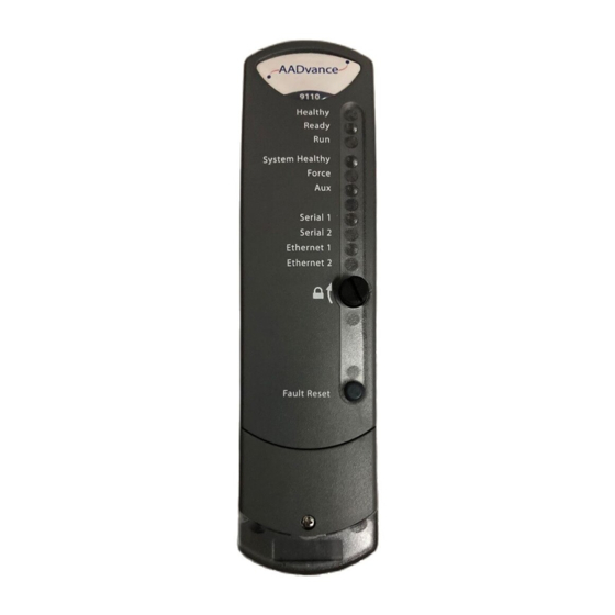
Page 111: Status Indicators On The T9110 Processor Module
• If Healthy is GREEN and all the other indicators on the module are OFF then the module has failed to boot up. • If Healthy is GREEN and Ready and Run are RED then the module is in its shutdown state. Rockwell Automation Publication ICSTT-RM448M-EN-P - February 2021... - Page 112 Quickly alternating Tx and Rx activity. No power and stays off while the module is booting up (10 to 20 seconds) GREEN Ethernet link present Ethernet 1 and 2 AMBER Tx or Rx activity on Ethernet Port Rockwell Automation Publication ICSTT-RM448M-EN-P - February 2021...
-
Page 113: System Startup
Check • Verify there is physical segregation of any mains supply circuits from the 24 Vdc controller circuits. • Review the arrangements of terminals and the provision of cable entries for field wiring. Rockwell Automation Publication ICSTT-RM448M-EN-P - February 2021... -
Page 114: Procedure To Verify Build State
3. Remove all modules from the controller. 4. Check that the circuit breakers and fuses of the correct capacity and rating are installed in the correct locations. 5. Check that all subsections are isolated from each other. Rockwell Automation Publication ICSTT-RM448M-EN-P - February 2021... -
Page 115: Power Distribution And First Power Up
• Refer to the Processor Module startup process. 8. Install the I/O modules. • Refer to the I/O Module startup process. 9. Check system status indications show the system is on-line and operating as expected. Rockwell Automation Publication ICSTT-RM448M-EN-P - February 2021... -
Page 116: Processor Module Startup Process
Will stay OFF as the Module boots up (10 to 20 seconds) then depends on data Ethernet 1 connection Will stay OFF as the Module boots up (10 to 20 seconds) then depends on data Ethernet 2 connection Rockwell Automation Publication ICSTT-RM448M-EN-P - February 2021... - Page 117 When the Run indicator goes AMBER push the Fault Reset button and the processor will show the following indications: Healthy GREEN Ready GREEN (will flash for a short time as the module educates) AMBER to GREEN (AMBER as the module educates) System Healthy GREEN Rockwell Automation Publication ICSTT-RM448M-EN-P - February 2021...
-
Page 118: I/O Module Startup Process
Install the Input/Output Module and turn the locking screw to the lock position. The module will provide the following status indications: Healthy GREEN Ready Channel 1 – 8 The input module will follow its startup sequence and the module will educate. Rockwell Automation Publication ICSTT-RM448M-EN-P - February 2021... -
Page 119: Processor Firmware Upgrades
• Select the T9110 module from the list • Browse to the T9110 module and select it • Select the version of firmware to be sent to the module • Update the module Rockwell Automation Publication ICSTT-RM448M-EN-P - February 2021... -
Page 120: Setting The Controller Ip Address For Communications
Driver" (if present) for normal Windows operation. 5. Disable the Windows Firewall, or any third-party firewalls and shields. 6. If using a laptop, disable Wireless. If there are multiple network connections, disable the connections not being used. The AADvance Rockwell Automation Publication ICSTT-RM448M-EN-P - February 2021... -
Page 121: Configure The Controller Resource Number In The Controller
4. Locate the controller in the list and make sure that the status of the controller is Configurable. 5. Double-click the MAC address in the Controller ID field. • The resource and IP Address dialog box is displayed. Rockwell Automation Publication ICSTT-RM448M-EN-P - February 2021... -
Page 122: Configure The Ip Address In The Controller
The procedure to configure the IP Address uses the AADvance Discover utility. Changes occur immediately and you do not have to start the controller again. To set the IP Address do the following: Rockwell Automation Publication ICSTT-RM448M-EN-P - February 2021... - Page 123 6. Enter the IP Address and Subnet Mask into the fields for each Ethernet port. 7. Enter the Gateway values for each processor module, then click Apply. • Returning to the main window of the utility, the controller status will shows In Progress and then Configurable. Rockwell Automation Publication ICSTT-RM448M-EN-P - February 2021...
- Page 124 Chapter 6 System Startup • The controller uses the new settings. Rockwell Automation Publication ICSTT-RM448M-EN-P - February 2021...
-
Page 125: Devising Tests For Functional Acceptance
Testing must be done on a known version of the controller. Record the type, serial number and physical location of each module so that the system can be dismantled, shipped and built with the modules in the same locations. Rockwell Automation Publication ICSTT-RM448M-EN-P - February 2021... - Page 126 Chapter 7 Functional Acceptance Testing Review and finalize the technical manuals which have been prepared for the maintenance and operation of the system. Rockwell Automation Publication ICSTT-RM448M-EN-P - February 2021...
-
Page 127: About Dismantling A System
It is necessary to make a plan for the collection, treatment, recovery and environmentally sound disposal of the equipment at the end of its life. Contact Rockwell Automation to discuss the applicable way to do this. Re-use Before disposing of serviceable items, contact Rockwell Automation and find out if it is possible to return unwanted items for possible future reconditioning. - Page 128 Chapter 8 Dismantling the AADvance System Notes: Rockwell Automation Publication ICSTT-RM448M-EN-P - February 2021...
-
Page 129: Base Units
Analogue input TA, 16 channel, dual T9833 Analogue input TA, 16 channel, TMR T9851 Digital output TA, 24Vdc, 8 channel, simplex, commoned T9852 Digital output TA, 24Vdc, 8 channel, dual T9881 Analogue output TA, 8 channel, simplex commoned Rockwell Automation Publication ICSTT-RM448M-EN-P - February 2021... -
Page 130: Expansion Cable Assembly
IEC 61131 Workbench, hard disk key, single user, single controller T9083U IEC 61131 Workbench, USB key, multiple controllers T9083D IEC 61131 Workbench, hard disk key, multiple controllers T9084U IEC 61131 Workbench, 5 user USB key, multiple controllers Rockwell Automation Publication ICSTT-RM448M-EN-P - February 2021... -
Page 131: Demonstration Unit
AADvance®-Trusted® SIS Workstation software AADvance® license T9030 OPC portal server T9033 AADvance DTM (for use with HART Pass-Through feature) Demonstration Unit Part No. Part Description T9141 AADvance Demonstration Unit (Including HMI) Miscellaneous Items Part No. Part Description Rockwell Automation Publication ICSTT-RM448M-EN-P - February 2021... - Page 132 Chapter 9 Parts List Notes: Rockwell Automation Publication ICSTT-RM448M-EN-P - February 2021...
- Page 133 Removed row for T9085. Added row for T9090, removed rows for T9901...T9906, in the Software section. Removed NFPA 87 from Glossary. Updated definition for proof test in Glossary. ICSTT-RM448L-EN-P, July 2019 Change Updated for Release 1.34 IEC 61508 Edition 2.0 certification Rockwell Automation Publication ICSTT-RM448M-EN-P - February 2021...
- Page 134 Issue 05, October 2010 Change Updates for UL Certification Issue 04, July 2010 Change Update for Release 1.1.1 Issue 03, November 2009 Change Update for Release 1.1 Issue 02, February 2009 Change Update for Product Titles Rockwell Automation Publication ICSTT-RM448M-EN-P - February 2021...
- Page 135 Appendix A History of Changes Issue 01, April 2008 Change First Issue Rockwell Automation Publication ICSTT-RM448M-EN-P - February 2021...
- Page 136 Appendix A History of Changes Notes: Rockwell Automation Publication ICSTT-RM448M-EN-P - February 2021...
-
Page 137: Glossary
The probability that a system will be able to carry out its designated function availability when required for use — normally expressed as a percentage. A sprung, plastic device to hold together two adjacent AADvance base units. backplane clip ® Part number T9904. Used in pairs. Rockwell Automation Publication ICSTT-RM448M-EN-P - February 2021... - Page 138 Common Industrial Protocol. A communications protocol, formally known as 'CIP™ over Ethernet/IP™', created by Rockwell Automation for the Logix controller family, and which is also supported by the AADvance controller. AADvance controllers use the protocol to exchange data with Logix controllers.
- Page 139 The set of internal input and output variables and defined words used in a dictionary program. A condition that exists if one or more of the elements disagree. discrepancy Digital input termination assembly. DITA Rockwell Automation Publication ICSTT-RM448M-EN-P - February 2021...
- Page 140 — for example a sounder or visual indicator. A centre from which the necessary fire protection or fire fighting measures can fire alarm receiving station be initiated at any time. Rockwell Automation Publication ICSTT-RM448M-EN-P - February 2021...
- Page 141 A collation of interfaces for field sensors (inputs) or final elements (outputs), I/O module arranged in a self-contained and standardized physical form factor. A series of international standards giving test and measurement techniques IEC 61000 for electromagnetic compatibility. Rockwell Automation Publication ICSTT-RM448M-EN-P - February 2021...
- Page 142 Also referred to as 'hot swap'. Where the Safety Instrumented Function only performs its designed function low demand mode on demand, and the frequency of demands is no greater than one per year. Rockwell Automation Publication ICSTT-RM448M-EN-P - February 2021...
- Page 143 In MODBUS communications, sending the diagnostic Query Data command pinging over a link and by receiving a reply ensuring that the link is healthy and the controller is able to communicate with the master. No process data is Rockwell Automation Publication ICSTT-RM448M-EN-P - February 2021...
- Page 144 (denoted PSTEUC) is the period a dangerous condition can exist before a hazardous event occurs without a safety system as a protection. A class of analogue variable stored in a floating, single-precision 32-bit format. real Rockwell Automation Publication ICSTT-RM448M-EN-P - February 2021...
- Page 145 SIL rating. SNCP (Safety Network Control Protocol) is the Safety Protocol that allows SNCP elements of an AADvance System to exchange data. SNCP is a SIL 3 certified Rockwell Automation Publication ICSTT-RM448M-EN-P - February 2021...
- Page 146 Independent third party certification against a defined range of international TÜV certification standards including IEC 61508. Rack unit. A unit of measure used to describe the height of equipment intended for mounting in a standard rack. Equivalent to 44.45mm (1-¾ inches). Rockwell Automation Publication ICSTT-RM448M-EN-P - February 2021...
- Page 147 A redundant system (m out of n) which requires at least m of the n channels to voting system be in agreement before the system can take action. The maximum voltage level that can be applied between circuits or withstand voltage components without causing a breakdown. Rockwell Automation Publication ICSTT-RM448M-EN-P - February 2021...
- Page 148 Notes: Rockwell Automation Publication ICSTT-RM448M-EN-P - February 2021...
- Page 149 AADvance Controller System Build Manual Rockwell Automation Publication ICSTT-RM448M-EN-P - February 2021...
- Page 150 At the end of life, this equipment should be collected separately from any unsorted municipal waste. Rockwell Automation maintains current product environmental information on its website at rok.auto/pec. AADvance, Allen-Bradley, ControlFLASH, expanding human possibility, ICS Triplex, ISaGRAF, RSLinx, Rockwell Software, Rockwell Automation, Trusted, and TechConnect are trademarks of Rockwell Automation, Inc.
Need help?
Do you have a question about the Allen-Bradley AADvance T9110 and is the answer not in the manual?
Questions and answers