Page 2
If this equipment is used in a manner not specified by the manufacturer, the protection provided by the equipment may be impaired. In no event will Rockwell Automation, Inc. be responsible or liable for indirect or consequential damages resulting from the use or application of this equipment.
Connect to the Controller Via a USB Cable ..... 42 Connect the Controller to an EtherNet/IP Network ... . . 43 Connecting to Different EtherNet/IP Network Topologies. . . 43 Rockwell Automation Publication 1769-UM021I-EN-P - May 2018...
Page 4
Change the IP Address of a Controller ......105 Change the Network IP Address with RSLinx Classic Software 106 Change the Network IP Address with Logix Designer Application Rockwell Automation Publication 1769-UM021I-EN-P - May 2018...
Page 5
Bus Off Detection and Recovery ......179 Rockwell Automation Publication 1769-UM021I-EN-P - May 2018...
Page 6
Monitor I/O Modules ........258 End Cap Detection and Module Faults ..... 259 Rockwell Automation Publication 1769-UM021I-EN-P - May 2018...
Change of state Coordinated System Time DHCP Dynamic Host Configuration Protocol DINT Signed double integer Device Level Ring Get System Value Human Machine Interface Immediate Output Internet Protocol Jump to Subroutine Master Control Relay Rockwell Automation Publication 1769-UM021I-EN-P - May 2018...
Universal Serial Bus Coordinated Universal Time Product Compatibility and For more information on controller firmware revisions and software application minimum requirements, go to the Rockwell Automation Product Download Center Compatibility and Download Center (PCDC) available at: http://compatibility.rockwellautomation.com/Pages/home.aspx You can access firmware for your CompactLogix 5370 controller in the Download section of the PCDC.
1756-PM010 Logix5000 Controllers Common Procedures Programming Manual, Provides links to a collection of programming manuals that describe how you can use publication 1756-PM001 procedures that are common to all Logix5000 controller projects. Rockwell Automation Publication 1769-UM021I-EN-P - May 2018...
Page 12
LOGIX-WP003 Industrial Automation Wiring and Grounding Guidelines, publication 1770-4.1 Provides general guidelines for installing a Rockwell Automation industrial system. Product Certifications website, Provides declarations of conformity, certificates, and other certification details. http://www.rockwellautomation.com/global/certification/overview.page You can view or download publications at .
Page 13
Among the features the CompactLogix 5370 controllers support, are dual EtherNet/IP ports on each controller and support for Integrated Motion over an EtherNet/IP network on some CompactLogix 5370 controllers. (1) Available at software version 31 and firmware revision 31. Rockwell Automation Publication 1769-UM021I-EN-P - May 2018...
• Distributed I/O - Multiple I/O module product lines over DeviceNet and EtherNet/IP networks Reset button If held in during controller powerup, it clears the user program from the internal memory of the controller. Rockwell Automation Publication 1769-UM021I-EN-P - May 2018...
POINTBus™ backplane current of 1 A. If you must use more local expansion modules than the POINTBus backplane current supports, you can install a 1734-EP24DC POINT I/O expansion power supply between local expansion modules to increase the POINTBus backplane power and meet your system requirements. Rockwell Automation Publication 1769-UM021I-EN-P - May 2018...
Connections from other controllers can also be broken. If an I/O connection to a device is interrupted, the result can be a loss of data. Rockwell Automation Publication 1769-UM021I-EN-P - May 2018...
EtherNet/IP system configuration for a 1769-L18ERM-BB1B controller. Figure 1 - Example 1769-L18ERM-BB1B Control System Configuration on an EtherNet/IP Network Stratix 5700™ 1769-L18ERM-BB1B PanelView™ Plus 7 Kinetix® 5500 1794-AENTR FLEX™ I/O 1734-AENTR POINT I/O Kinetix 5500 Rockwell Automation Publication 1769-UM021I-EN-P - May 2018...
Page 19
Figure 3 - Example 1769-L33ERM Control System Configuration on an EtherNet/IP Network • 1769-AENTR Stratix 5700 1769-L33ERM Control System • 1769 Compact I/O Kinetix 5500 PanelView Plus 7 Kinetix 5500 1794-AENTR FLEX I/O 1734-AENTR POINT I/O Rockwell Automation Publication 1769-UM021I-EN-P - May 2018...
Overload Relay • 1734-ADN POINT I/O 1606-XLDNET • POINT I/O For more information on how to use the CompactLogix 5370 L2 or L3 controllers on DeviceNet networks, see Communicate over Networks on page 121. Rockwell Automation Publication 1769-UM021I-EN-P - May 2018...
Page 23
In addition to this publication, see the following: • Industrial Automation Wiring and Grounding Guidelines, publication 1770-4.1, for additional installation requirements • NEMA 250 and IEC 60529, as applicable, for explanations of the degrees of protection provided by enclosures Rockwell Automation Publication 1769-UM021I-EN-P - May 2018...
Page 24
Classe I, Division 2. • If this product contains batteries, they must only be changed in an area known to be • S'assurer que l'environnement est classé non nonhazardous. dangereux avant de changer les piles. Rockwell Automation Publication 1769-UM021I-EN-P - May 2018...
Page 25
• This equipment must be installed in an enclosure providing at least IP54 protection when applied in Zone 2 environments. • This equipment shall be used within its specified ratings defined by Rockwell Automation. • Provision shall be made to prevent the rated voltage from being exceeded by transient disturbances of more than 40% when applied in Zone 2 environments.
• The control system includes the controller, an embedded power supply, and embedded I/O points. Removable Connector for Embedded Power Supply Embedded I/O Module Rockwell Automation Publication 1769-UM021I-EN-P - May 2018...
Page 27
L16ER, L18ER, L18ERM Controllers, and series A L19ER controllers. • The controller has 16 embedded digital input points and 16 embedded digital output points. You wire the input and output points via a removable connector. Rockwell Automation Publication 1769-UM021I-EN-P - May 2018...
Page 28
Failure to do so could result in equipment damage or injury from electric shock. For more information on how to terminate the end of your system, see page 1734 POINT I/O modules support removal and insertion under power. Rockwell Automation Publication 1769-UM021I-EN-P - May 2018...
To install a CompactLogix 5370 L1 controller, follow these steps. Install the Secure Digital Card. Install the System. Connect to the Controller Via a USB Cable. Connect the Controller to an EtherNet/IP Network. Rockwell Automation Publication 1769-UM021I-EN-P - May 2018...
Consider the following when deciding to lock the card before installation: – If the card is unlocked, the controller can write data to it or read data from it. Unlocked Locked 2. Open the door for the SD card. Rockwell Automation Publication 1769-UM021I-EN-P - May 2018...
Page 31
We recommend that you keep the SD card door closed during normal system operation. For more information on how to use the SD card, see Use a Secure Digital Card on page 297. Rockwell Automation Publication 1769-UM021I-EN-P - May 2018...
The use of other DIN rail materials (for example, aluminum or plastic) that can corrode, oxidize, or are poor conductors, can result in improper or intermittent grounding. Secure DIN rail to mounting surface approximately every 200 mm (7.8 in.) and use end-anchors appropriately. Rockwell Automation Publication 1769-UM021I-EN-P - May 2018...
Page 33
Allow 50 mm (2 in.) of space on all sides, as shown. This spacing provides ventilation and electrical isolation. 50 mm (2 in.) 50 mm 50 mm (2 in.) (2 in.) Side Side 50 mm Bottom (2 in.) Rockwell Automation Publication 1769-UM021I-EN-P - May 2018...
Page 34
(5.67 in.) This graphic shows the system dimensions with Expansion I/O modules installed. 12.00 mm (0.47 in.) 105 mm 100.00 mm (4.13 in.) (3.94 in.) 130.00 mm (5.11 in.) 144.00 mm (5.67 in.) Rockwell Automation Publication 1769-UM021I-EN-P - May 2018...
Automation publication 1770-4.1, for additional information. Install the Controller Complete these steps to install the controller. 1. Pull out the locking tabs. 2. Slide the controller into position on the DIN rail and push the locking tabs in. Rockwell Automation Publication 1769-UM021I-EN-P - May 2018...
1. Insert the end opposite the handle into the base unit. This end has a curved section that engages with the wiring base. 2. Rotate the RTB into the wiring base until it locks itself in place. Rockwell Automation Publication 1769-UM021I-EN-P - May 2018...
144. For more information on how to provide power to input or output devices that are connected to the embedded I/O modules of the controller and local expansion modules, see page 144. Rockwell Automation Publication 1769-UM021I-EN-P - May 2018...
Page 38
• This section assumes that any DIN rail you use has been grounded following Industrial Automation Wiring and Grounding Guidelines, publication 1770-4.1. • The embedded power supply of the CompactLogix 5370 L1 controller provides power to the controller and POINTBus backplane. Rockwell Automation Publication 1769-UM021I-EN-P - May 2018...
Page 39
WARNING: If you connect or disconnect wiring while the field-side power is on, an electrical arc can occur. This could cause an explosion in hazardous location installations. Be sure that power is removed or the area is nonhazardous before proceeding. Rockwell Automation Publication 1769-UM021I-EN-P - May 2018...
Page 40
6. Connect the wire that is connected to the 24V DC- terminal on the external 24V DC power source to the VDC- terminal. The VDC- terminal is the second from the top on the removable connector. Rockwell Automation Publication 1769-UM021I-EN-P - May 2018...
Page 41
8. Secure the removable connector in place. 9. Turn on power to the external 24V DC power source. The following graphic shows an external 24V DC power source that is connected to a CompactLogix 5370 L1 controller. Rockwell Automation Publication 1769-UM021I-EN-P - May 2018...
The USB cable is not to exceed 3.0 m (9.84 ft) and must not contain hubs. WARNING: Do not use the USB port in hazardous locations. Plug the USB cable into the CompactLogix 5370 L1 controller. Rockwell Automation Publication 1769-UM021I-EN-P - May 2018...
• Star network topology - One port on the controller is connected to the network. There are connection and configuration requirements for each EtherNet/IP network topology. For more information, see EtherNet/IP Network Topologies on page 125. Rockwell Automation Publication 1769-UM021I-EN-P - May 2018...
Page 44
Chapter 2 Install the CompactLogix 5370 L1 Controller Notes: Rockwell Automation Publication 1769-UM021I-EN-P - May 2018...
Page 45
In addition to this publication, see the following: • Industrial Automation Wiring and Grounding Guidelines, publication 1770-4.1, for additional installation requirements • NEMA 250 and IEC 60529, as applicable, for explanations of the degrees of protection provided by enclosures Rockwell Automation Publication 1769-UM021I-EN-P - May 2018...
Page 46
Classe I, Division 2. • If this product contains batteries, they must only be changed in an area known to be • S'assurer que l'environnement est classé non nonhazardous. dangereux avant de changer les piles. Rockwell Automation Publication 1769-UM021I-EN-P - May 2018...
Page 47
• This equipment must be installed in an enclosure providing at least IP54 protection when applied in Zone 2 environments. • This equipment shall be used within its specified ratings defined by Rockwell Automation. • Provision shall be made to prevent the rated voltage from being exceeded by transient disturbances of more than 40% when applied in Zone 2 environments.
1769 CompactBus backplane as local expansion modules. For more information on how to use embedded I/O points and local expansion modules, see Chapter 8, Use I/O Modules with CompactLogix 5370 L2 Controllers on page 181. Rockwell Automation Publication 1769-UM021I-EN-P - May 2018...
Avoid frequent writes when logging data. We recommend that you log data to a buffer in the memory of your controller and limit the number of times data is written to removable media. Rockwell Automation Publication 1769-UM021I-EN-P - May 2018...
1. Verify that the SD card is locked or unlocked according to your preference. Consider the following when deciding to lock the card before installation: – If the card is unlocked, the controller can write data to it or read data from it. Unlocked Locked Rockwell Automation Publication 1769-UM021I-EN-P - May 2018...
Page 51
We recommend that you keep the SD card door closed during normal system operation. For more information on how to use the SD card, see Use a Secure Digital Card on page 297. Rockwell Automation Publication 1769-UM021I-EN-P - May 2018...
You can mount the CompactLogix 5370 L2 controller on the following DIN rails: • EN 50 022 - 35 x 7.5 mm (1.38 x 0.30 in.) • EN 50 022 - 35 x 15 mm (1.38 x 0.59 in.) Rockwell Automation Publication 1769-UM021I-EN-P - May 2018...
Page 53
This graphic shows the system dimensions for the 1769-L24ER-QB1B controller. 27.65 mm 59.70 mm 3.06 mm (1.09 in.) (2.35 in.) (0.12 in.) 105 mm (4.13 in.) 118.00 mm (4.65 in.) 2.8 mm 115.00 mm (0.12 in.) (4.53 in.) Rockwell Automation Publication 1769-UM021I-EN-P - May 2018...
Page 54
This graphic shows the system dimensions for the 1769-L24ER-QBFC1B controller. 27.65 mm 3.06 mm 84.70 mm (1.09 in.) (0.12 in.) (3.33 in.) 105 mm (4.13 in.) 118.00 mm (4.65 in.) 140.00 mm 2.8 mm (5.51 in.) (0.12 in.) Rockwell Automation Publication 1769-UM021I-EN-P - May 2018...
Page 55
This graphic shows the system dimensions for the 1769-L27ERM-QBFC1B controller. 3.06 mm 27.65 mm 84.70 mm (0.12 in.) (1.09 in.) (3.33 in.) 105 mm (4.13 in.) 118.00 mm (4.65 in.) 140.00 mm 2.8 mm (5.51 in.) (0.12 in.) Rockwell Automation Publication 1769-UM021I-EN-P - May 2018...
Page 56
3. Return the assembled modules to the clean work surface, including any previously mounted modules. 4. Drill and tap the mounting holes for the recommended M4 or #8 screw. Rockwell Automation Publication 1769-UM021I-EN-P - May 2018...
Page 57
1. Hook the DIN rail latch at the top of the back of the controller on the DIN rail. 2. Swing the controller downward until it touches the DIN rail and press the controller against the DIN rail until it clicks in place. Rockwell Automation Publication 1769-UM021I-EN-P - May 2018...
2. Hook the top of the controller on the DIN rail. 3. Swing it downward until the controller is flush against the DIN rail and push it down against the DIN rail. 4. Push the controller against the DIN rail. Rockwell Automation Publication 1769-UM021I-EN-P - May 2018...
Page 59
CompactLogix 5370 L2 controller system either at the end of the controller. You must also install an end cap at the end of any local expansion modules that can be installed onto the controller. Rockwell Automation Publication 1769-UM021I-EN-P - May 2018...
When replacing the terminal block, torque the retaining screws to 0.46 N m (4.1 lb•in). • Item Description Wiring the finger-safe cover Lower retaining screws Upper retaining screws Rockwell Automation Publication 1769-UM021I-EN-P - May 2018...
IMPORTANT The 1606-XLDNET4 power supply is not certified for use in all applications, for example, you cannot use it in hazardous locations. Read the points in Connect Power to the Control System on page 62 before choosing the external power supply for your application. Rockwell Automation Publication 1769-UM021I-EN-P - May 2018...
Page 63
4. Strip 8 mm (0.31 in.) insulation from the end of the wire that you connect to the +24VDC terminal on the controller. 5. Connect the wire from the 24VDC+ terminal on the external 24V DC power source to the +24VDC terminal on the controller. Rockwell Automation Publication 1769-UM021I-EN-P - May 2018...
Page 64
Do not reapply power from the external power supply to the embedded power supply of the CompactLogix 5370 L2 controller until after the OK status indicator of the controller is off. Rockwell Automation Publication 1769-UM021I-EN-P - May 2018...
The USB cable is not to exceed 3.0 m (9.84 ft) and must not contain hubs. WARNING: Do not use the USB port in hazardous locations. Plug the USB cable into the CompactLogix 5370 L2 controller. Rockwell Automation Publication 1769-UM021I-EN-P - May 2018...
• Star network topology - One port on the controller is connected to the network. There are connection and configuration requirements for each EtherNet/IP network topology. For more information, see EtherNet/IP Network Topologies on page 125. Rockwell Automation Publication 1769-UM021I-EN-P - May 2018...
Page 67
In addition to this publication, see the following: • Industrial Automation Wiring and Grounding Guidelines, publication 1770-4.1, for additional installation requirements • NEMA 250 and IEC 60529, as applicable, for explanations of the degrees of protection provided by enclosures Rockwell Automation Publication 1769-UM021I-EN-P - May 2018...
Page 68
Classe I, Division 2. • If this product contains batteries, they must only be changed in an area known to be • S'assurer que l'environnement est classé non nonhazardous. dangereux avant de changer les piles. Rockwell Automation Publication 1769-UM021I-EN-P - May 2018...
Page 69
• This equipment must be installed in an enclosure providing at least IP54 protection when applied in Zone 2 environments. • This equipment shall be used within its specified ratings defined by Rockwell Automation®. • Provision shall be made to prevent the rated voltage from being exceeded by transient disturbances of more than 40% when applied in Zone 2 environments.
Avoid frequent writes when logging data. We recommend that you log data to a buffer in the memory of your controller and limit the number of times data is written to removable media. Rockwell Automation Publication 1769-UM021I-EN-P - May 2018...
1. Verify that the SD card is locked or unlocked according to your preference. Consider the following when deciding to lock the card before installation: – If the card is unlocked, the controller can write data to it or read data from it. Unlocked Locked Rockwell Automation Publication 1769-UM021I-EN-P - May 2018...
Page 73
We recommend that you keep the SD card door closed during normal system operation. For more information on how to use the SD card, see Use a Secure Digital Card on page 297. Rockwell Automation Publication 1769-UM021I-EN-P - May 2018...
This could cause an explosion in hazardous location installations. Be sure that power is removed or the area is nonhazardous before proceeding. Rockwell Automation Publication 1769-UM021I-EN-P - May 2018...
Page 75
3. Use the upper and lower tongue-and-groove slots to secure the controller and power supply together. Tongue-and-groove Slots 4. Move the power supply back along the tongue-and-groove slots until the bus connectors align with each other. Rockwell Automation Publication 1769-UM021I-EN-P - May 2018...
Page 76
8. Wire the 1769 Compact I/O power supply according to the directions in the Compact I/O Expansion Power Supplies installation instructions, publication 1769-IN028. If you are using local expansion modules, see Local Expansion Modules on page 236. Rockwell Automation Publication 1769-UM021I-EN-P - May 2018...
If you wire the terminal block with the fingersafe cover removed, you cannot put it back on the terminal block because of wires in the way. Rockwell Automation Publication 1769-UM021I-EN-P - May 2018...
Figure 6 - Example CompactLogix 5370 L3 Control Systems Horizontal Orientation Bank 1 Bank 2 1769-CRLx Cable Bank 3 1769-CRLx Cable Bank 1 1769-CRRx Cable Vertical Orientation Bank 2 Rockwell Automation Publication 1769-UM021I-EN-P - May 2018...
Page 79
Allow 50 mm (2 in.) of space on all sides, as shown. This spacing provides ventilation and electrical isolation. 50 mm (2 in.) 50 mm 50 mm (2 in.) (2 in.) Side Side Bottom 50 mm (2 in.) Rockwell Automation Publication 1769-UM021I-EN-P - May 2018...
Page 80
(1.38 in.) 132 mm (5.20 in.) 118 mm (4.65 in.) 52.5 mm 35 mm 35 mm 35 mm 35 mm (2.07 in.) (1.38 in.) (1.38 in.) (1.38 in.) (1.38 in.) 105 mm (4.13 in.) Rockwell Automation Publication 1769-UM021I-EN-P - May 2018...
See Industrial Automation Wiring and Grounding Guidelines, Rockwell Automation publication 1770-4.1, for additional information. For more information, see the Industrial Automation Wiring and Grounding Guidelines, publication 1770-4.1. Rockwell Automation Publication 1769-UM021I-EN-P - May 2018...
Page 82
TIP If you are mounting more modules, mount only the last one of this group and put the others aside. This process reduces remounting time when you are drilling and tapping the next group of modules. 7. Repeat steps 1 6 for any remaining modules. … Rockwell Automation Publication 1769-UM021I-EN-P - May 2018...
1769 Compact I/O power supply your application uses. For more information on how to connect power to your CompactLogix 5370 L3 control system, see the Compact I/O Expansion Power Supplies Installation Instructions, publication 1769-IN028. Rockwell Automation Publication 1769-UM021I-EN-P - May 2018...
, 1769-L38ERMO controller, see the Armor CompactLogix Controllers Installation Instructions, publication 1769-IN021. (1) Available at software version 31 and firmware revision 31. Plug the USB cable into the CompactLogix 5370 L3 controller as shown. Rockwell Automation Publication 1769-UM021I-EN-P - May 2018...
Depending on the Ethernet network topology of your application, you can connect both ports of the controller to the EtherNet/IP network. For more information on EtherNet/IP network topologies, see page 125. Rockwell Automation Publication 1769-UM021I-EN-P - May 2018...
• Star network topology - One port on the controller is connected to the network. For more information, see EtherNet/IP Network Topologies on page 125. Rockwell Automation Publication 1769-UM021I-EN-P - May 2018...
Page 87
• Studio 5000 environment, version 21 or later • Studio 5000 environment, version 28 or later for 1769-L19ER-BB1B controllers CompactLogix 5370 controllers require a network Internet Protocol (IP) address to operate on an EtherNet/IP network. Rockwell Automation Publication 1769-UM021I-EN-P - May 2018...
Page 88
IMPORTANT CompactLogix 5370 controllers have two EtherNet/IP ports to connect to an EtherNet/IP network. The ports carry the same network traffic as part of the embedded switch of the controller. However, the controller uses only one IP address. Rockwell Automation Publication 1769-UM021I-EN-P - May 2018...
USB cable to set the initial IP address of the controller with RSLinx Classic software or the application. Figure 7 describes how to set the IP address of your CompactLogix 5370 controller on a power cycle during initial installation or after operation has begun. Rockwell Automation Publication 1769-UM021I-EN-P - May 2018...
Page 90
Is controller Is controller DHCP- enabled? BOOTP- enabled? Use BOOTP server to Use DHCP to set Controller has an IP address. set the IP address. the IP address. Rockwell Automation Publication 1769-UM021I-EN-P - May 2018...
• A CompactLogix 5370 controller ships from the factory without an IP address and BOOTP-enabled. • This section describes how to use a Rockwell Automation® BOOTP/ DHCP server. If you use another BOOTP/DHCP server, contact your network administrator to verify that you are using it correctly.
Page 92
Complete these steps to set the IP address of the controller with the BOOTP/DHCP server. IMPORTANT To use the BOOTP server, your computer and the controller must be connected to the same EtherNet/IP network. 1. Start the BOOTP/DHCP software. Rockwell Automation Publication 1769-UM021I-EN-P - May 2018...
Page 93
Name fields are optional. 4. Click OK. The Request History panel appears with the hardware addresses of all devices that issue BOOTP requests. This process can take some time to complete. 5. Select the appropriate module. Rockwell Automation Publication 1769-UM021I-EN-P - May 2018...
Page 94
BOOTP request. IMPORTANT If you do not click Disable BOOTP/DHCP on a power cycle, the host controller clears the current IP configuration and begins sending BOOTP requests again. Rockwell Automation Publication 1769-UM021I-EN-P - May 2018...
Page 95
4. Navigate to the USB network. 5. Right-click on the controller and choose Module Configuration. 6. Click the Port Configuration tab. 7. From the Network Configuration Type, click Static to disable BOOTP/DHCP. 8. Click OK. Rockwell Automation Publication 1769-UM021I-EN-P - May 2018...
Page 96
3. Right-click on the controller and choose Properties. 4. On the Controller Properties dialog box, click the Internet Protocol tab. 5. Click Manually configure IP settings. 6. Click OK. 7. When prompted to confirm the IP address setting, click Yes. Rockwell Automation Publication 1769-UM021I-EN-P - May 2018...
Page 97
ATTENTION: The EtherNet/IP communication module must be assigned a fixed network address. The IP address of this module must not be dynamically provided. Failure to observe this precaution may result in unintended machine motion or loss of process control. Rockwell Automation Publication 1769-UM021I-EN-P - May 2018...
Failure to observe this precaution can result in unintended machine motion or loss of process control. If you use the Rockwell Automation BOOTP or DHCP server in an uplinked subnet where a DHCP server exists, a controller can procure an address from the enterprise server before the Rockwell Automation utility even sees the controller.
3. If no RSWho dialog box appears, from the Communications pull-down menu, choose RSWho. The RSWho dialog box appears and includes the USB driver. 4. Right-click the EtherNet/IP module and choose Module Configuration. The Module Configuration dialog box appears. Rockwell Automation Publication 1769-UM021I-EN-P - May 2018...
Page 100
SD card in a way that does not overwrite the IP address at the next controller power cycle. For more information on how to use the SD card, see Chapter 12, Use a Secure Digital Card on page 297. Rockwell Automation Publication 1769-UM021I-EN-P - May 2018...
1. Start the application. 2. Set the Project Path. a. Click RSWho. The RSWho dialog box appears. b. Navigate over the USB network and select the CompactLogix 5370 controller. c. Click Set Project Path. Rockwell Automation Publication 1769-UM021I-EN-P - May 2018...
Page 102
3. Click Download. 4. Click Download again. The new project is downloaded to the controller and the project goes online, in Remote Program or Program mode. 5. Right-click the controller name and choose Properties. Rockwell Automation Publication 1769-UM021I-EN-P - May 2018...
Page 103
7. Click Manually configure IP settings. 8. Enter desired IP address and other configuration information and click OK. 9. When prompted to confirm the IP address setting, click Yes. The controller now uses the newly set IP address. Rockwell Automation Publication 1769-UM021I-EN-P - May 2018...
• The project that is stored on the SD card is configured with the Load Image parameter set to On Power Up. For more information on how to use the SD card, see Chapter 12, Use a Secure Digital Card on page 297. Rockwell Automation Publication 1769-UM021I-EN-P - May 2018...
• Company policies and procedures that deal with plant floor network installation and maintenance • Level of involvement by IT personnel in plant-floor network installation and maintenance • Type of training that is offered to control engineers and maintenance personnel Rockwell Automation Publication 1769-UM021I-EN-P - May 2018...
Configuration Type section of the dialog box. IMPORTANT If you click Dynamic, on a power cycle, the controller clears the current IP configuration and starts to send BOOTP or DHCP requests, depending on the controller configuration. 5. Click OK. Rockwell Automation Publication 1769-UM021I-EN-P - May 2018...
3. Right-click the controller name and choose Properties. You can also right-click the Ethernet node in the I/O Configuration section and choose Properties. The Controller Properties dialog box appears on the Internet Protocol tab. Rockwell Automation Publication 1769-UM021I-EN-P - May 2018...
• Power is cycled to the controller with the SD card installed. For more information on how to use the SD card, see Chapter 12, Use a Secure Digital Card on page 297. Rockwell Automation Publication 1769-UM021I-EN-P - May 2018...
Use the Secure Digital Card to Load Firmware on page 117 exist. The firmware is available with the application or you can download it from the support website. Go to http://www.rockwellautomation.com/support. Rockwell Automation Publication 1769-UM021I-EN-P - May 2018...
CompactLogix 5370 controllers with slight variations in screens. 1. Verify that a connection exists between your computer and the CompactLogix 5370 controller. 2. Choose Start>All Programs>FLASH Programming Tools>ControlFLASH. 3. When the Welcome dialog box appears, click Next. Rockwell Automation Publication 1769-UM021I-EN-P - May 2018...
Page 111
• The target device is not in the proper mode to accept an update in ControlFLASH. Rockwell Automation Publication 1769-UM021I-EN-P - May 2018...
Page 112
Complete Software Tasks Required at CompactLogix 5370 Controller Installation 7. Choose the revision level to which you want to update the controller and click Next. 8. To start the update of the controller, click Finish and click Yes. Rockwell Automation Publication 1769-UM021I-EN-P - May 2018...
Page 113
If you must update the firmware revision on any 1734 POINT I/O™ modules that are used as local expansion modules, you must do so before installing them in the CompactLogix 5370 L1 control system. Rockwell Automation Publication 1769-UM021I-EN-P - May 2018...
CompactLogix 5370 controllers with slight variations in screens. 1. Make sure that the network connection is made and your network driver is configured in RSLinx Classic software. 2. Create a controller project. 3. To specify the controller path, click RSWho. Rockwell Automation Publication 1769-UM021I-EN-P - May 2018...
Page 115
A dialog box appears to indicate that the project revision and controller firmware revision are different. 5. Click Update Firmware. 6. Use the checkbox and pull-down menu to choose your controller and firmware revision. Rockwell Automation Publication 1769-UM021I-EN-P - May 2018...
Page 116
8. When the Update Firmware dialog box appears, click Yes. Before the firmware update begins, you can be warned about your controller missing its SD card. Take the required action, typically click The firmware update begins. Rockwell Automation Publication 1769-UM021I-EN-P - May 2018...
• The firmware revision in the project that is stored on the SD card differs from the firmware revision on the CompactLogix 5370 controller. For more information on how to use the SD card, see Chapter 12, Use a Secure Digital Card on page 297. Rockwell Automation Publication 1769-UM021I-EN-P - May 2018...
Be sure that power is removed or the area is nonhazardous before proceeding. This graphic shows the mode switch on a CompactLogix 5370 L1 controller. This graphic shows the mode switch on a CompactLogix 5370 L2 controller. Rockwell Automation Publication 1769-UM021I-EN-P - May 2018...
Page 119
• Create, modify, and delete tasks, programs, or routines. • Change the port configuration of the controller, advanced port configuration, nor network configuration settings. You cannot perform these tasks: • Use the controller to execute (scan) tasks. Rockwell Automation Publication 1769-UM021I-EN-P - May 2018...
Page 120
• Create, modify, and delete tasks, programs, or routines. • Download projects. • Edit online. • The controller does not execute (scan) tasks. Remote Test • Execute tasks with outputs disabled. • Edit online. Rockwell Automation Publication 1769-UM021I-EN-P - May 2018...
EtherNet/IP network to communicate with Ethernet devices that do not support the EtherNet/IP application protocol. For more information on socket interface transactions, see Socket Interface with 
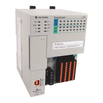
CompactLogix 5370 Controllers on page 131. Rockwell Automation Publication 1769-UM021I-EN-P - May 2018...
• Support for Integrated Motion over an EtherNet/IP network - Only the following controllers support this functionality: – 1769-L18ERM-BB1B – 1769-L27ERM-QBFC1B – 1769-L30ERM – 1769-L33ERM – 1769-L33ERMO – 1769-L36ERM – 1769-L36ERMO – 1769-L37ERM – 1769-L37ERMK – 1769-L37ERMO Rockwell Automation Publication 1769-UM021I-EN-P - May 2018...
1769-L19ER-BB1B 1769-L24ER-QB1B 1769-L24ER-QBFC1B, 1769-L24ER-QBFC1BK 1769-L27ERM-QBFC1B 1769-L30ER 1769-L30ERM, 1769-L30ERMK 1769-L30ER-NSE 1769-L33ER 1769-L33ERM, 1769-L33ERMK 1769-L33ERMO (1) Available at software version 31 and firmware revision 31. (1) Available at software version 31 and firmware revision 31. Rockwell Automation Publication 1769-UM021I-EN-P - May 2018...
Page 124
• HMI devices that are included in the I/O configuration section, for example, PanelView™ Plus terminals • Linking devices, such as the 1788-EN2DNR, Ethernet-to-DeviceNet linking device or 1788-EN2DNROM, On-machine Ethernet-to- DeviceNet linking device Rockwell Automation Publication 1769-UM021I-EN-P - May 2018...
DLR network topologies automatically convert to linear network topologies when a fault is detected. The conversion to the new network topology maintains communication of data on the network. The fault condition is typically easily detected and corrected. Rockwell Automation Publication 1769-UM021I-EN-P - May 2018...
Page 126
1769-L18ERM-BB1B control system using a DLR network topology. Figure 8 - Example 1769-L18ERM-BB1B Control System Using DLR Network Topology Stratix 5700™ 1769-L18ERM-BB1B PanelView Plus 7 Kinetix® 5500 1794-AENTR FLEX™ I/O 1734-AENTR POINT I/O™ Kinetix 5500 Rockwell Automation Publication 1769-UM021I-EN-P - May 2018...
Page 127
Figure 10 - Example 1769-L33ERM Control System Using a DLR Network Topology • 1769-AENTR Stratix 5700 1769-L33ERM Control System • 1769 Compact I/O Kinetix 5500 PanelView Plus 7 Kinetix 5500 1794-AENTR FLEX I/O 1734-AENTR POINT I/O Rockwell Automation Publication 1769-UM021I-EN-P - May 2018...
Page 128
Figure 12 - Example 1769-L24ER-QB1B Control System Using a Linear Network Topology 1734-AENTR POINT I/O 1734-AENTR FLEX I/O PanelView Plus LINK 1 LINK 2 PORT 1 PORT 2 AUX POWER 1732E-IB16M12R • Kinetix 350 1769-L24ER-QB1B • 1783-ETAP Rockwell Automation Publication 1769-UM021I-EN-P - May 2018...
Page 129
1769-L18ERM-BB1B control system using a star topology. Figure 14 - Example1769-L18ERM-BB1B Control System Using a Star Network Topology IP Address: ENET Address: 00:00:BC:66:0F:C7 1769-L18ERM-BB1B 1769-L18ERM-BB1B LINK 1 LINK 2 Stratix 6000™ PanelView Plus 1732E-IB16M12R 1734-AENTR POINT I/O Kinetix 350 Rockwell Automation Publication 1769-UM021I-EN-P - May 2018...
Page 130
Figure 16 - Example 1769-L33ERM Control System Using a Star Network Topology 1769-L33ERM 00:00:BC:2E:69:F6 1 (Front) 1 (Front) 1 (Front) 2 (Rear) Stratix 6000 PanelView Plus Kinetix 6500 1734-AENTR POINT I/O PowerFlex 525 Rockwell Automation Publication 1769-UM021I-EN-P - May 2018...
When you configure a message for a CompactLogix 5370 controller, make sure the Connected checkbox on the Message Configuration dialog box is cleared. For more information on socket interface, see EtherNet/IP Socket Interface Application Technique, publication ENET-AT002. Rockwell Automation Publication 1769-UM021I-EN-P - May 2018...
I/O modules are maintained, verify that the EtherNet/IP devices use the minimum firmware revision level of the product that is required to support QoS technology. For more information on the following, see Rockwell Automation Knowledgebase Tech Note 66325 (the document is available at http://www.rockwellautomation.com/knowledgebase/): •...
Page 133
(2) Total packet rate capacity = I/O Produced Tag, max + HMI/MSG, max Packet rates vary depending on packet size. For more detailed specifications, see the capacity section of the EDS file for the catalog number. (3) These are the maximum numbers of CIP I/O connections. Rockwell Automation Publication 1769-UM021I-EN-P - May 2018...
(2) We recommend that you use RSLinx Classic software, version 3.51.00 or later, with the Studio 5000 environment, version 21.00.00 or later. (3) RSLinx version 3.74.00 is recommended for use with the 1769-L19ER-BB1B controller. Rockwell Automation Publication 1769-UM021I-EN-P - May 2018...
Page 135
1769-L33ERM using a DeviceNet network. Figure 18 - Example 1769-L33ERM Control System Using a DeviceNet Network • 1769-L24ER-QB1B DeviceNet Connection • 1769-SDN Scanner 1606-XLDNET E3 Electronic • 1734-ADN POINT I/O Overload Relay • POINT I/O Rockwell Automation Publication 1769-UM021I-EN-P - May 2018...
1769-SDN scanner and the power supply. The power supply distance rating of the 1769-SDN scanner as a design consideration differs by CompactLogix L2 controller catalog number. Rockwell Automation Publication 1769-UM021I-EN-P - May 2018...
Page 137
1769-SDN scanner can be installed in slot 3 of the local expansion modules, as shown in the following graphic. Three modules between the power supply and the 1769-SDN scanner. With this controller catalog number, you can only install up to two local expansion modules between the controller and the 1769-SDN scanner. Rockwell Automation Publication 1769-UM021I-EN-P - May 2018...
Page 138
1769-SDN scanner is shown as module [5] in this location but considered the fourth module when counting modules to meet power supply distance rating requirements. Rockwell Automation Publication 1769-UM021I-EN-P - May 2018...
Page 139
Local Bank 1769-SDN Scanner Installed in a 1769-L36ERM Control System Meeting the Power Supply Distance Rating Requirements of the Scanner Extra Bank Rockwell Automation Publication 1769-UM021I-EN-P - May 2018...
For more information on 1769 Compact I/O power supply maximum current capacity and calculations you can use to design the modules that are used in local or extra banks, see Calculate System Power Consumption on page 243. Rockwell Automation Publication 1769-UM021I-EN-P - May 2018...
Page 141
Communicate over Networks Chapter 6 Notes: Rockwell Automation Publication 1769-UM021I-EN-P - May 2018...
Page 142
Chapter 6 Communicate over Networks Rockwell Automation Publication 1769-UM021I-EN-P - May 2018...
24V DC nominally with an input range of 10…28.8V DC. This graphic shows the removable connector. IMPORTANT The controller is grounded once it is installed on a DIN rail as described in Mount the System on page Rockwell Automation Publication 1769-UM021I-EN-P - May 2018...
Page 145
– Limit field power current to 3 A or use a 1734-FPD module to avoid blowing the internal fuse. – Install a user-replaceable fuse with overcurrent protection of 4…6 A @ 52.5…68.25 I2t in line between the incoming power and the FP+ terminal. Rockwell Automation Publication 1769-UM021I-EN-P - May 2018...
Page 146
WARNING: If you connect or disconnect wiring while the field-side power is on, an electrical arc can occur. This could cause an explosion in hazardous location installations. Be sure that power is removed or the area is nonhazardous before proceeding. Rockwell Automation Publication 1769-UM021I-EN-P - May 2018...
Page 147
4. Connect the wire that is connected to the + terminal on the external 24V DC power source to the FP+ terminal. The FP+ terminal is the fourth terminal from the top on the removable connector. Rockwell Automation Publication 1769-UM021I-EN-P - May 2018...
Page 148
The following graphic shows separate external 24V DC power supply that is connected to the VDC+/VDC- and FP+/FP- terminals on the removable connector, respectively. IMPORTANT: No wires are connected to the NC terminal. Rockwell Automation Publication 1769-UM021I-EN-P - May 2018...
FP+ and FP- terminals. For more information on how to connect the external power source to the FP+ and FP- terminals on the series B controller, page 146. Rockwell Automation Publication 1769-UM021I-EN-P - May 2018...
Page 150
2. Use a small screwdriver to push the spring release clip and insert the wire. 3. With the wire in place, pull the screwdriver off the spring release clip. 4. Repeat step 2 for all embedded I/O wires that are needed in your application. Rockwell Automation Publication 1769-UM021I-EN-P - May 2018...
Page 151
4. Disconnect any wires from the connector. 5. Connect any wires to the replacement connector. 6. Push the replacement connector back into the I/O module. 7. Secure the connector to the I/O module with the small screwdriver. Rockwell Automation Publication 1769-UM021I-EN-P - May 2018...
Page 152
For series A L1 controllers only, you must use a separate, dedicated Class 2 power supply for the CompactLogix 5370 L1 controller and a separate power supply for the embedded I/O module (see Appendix Rockwell Automation Publication 1769-UM021I-EN-P - May 2018...
Page 153
Power Supply 1 Power 2-wire Prox 3-wire Prox Supply 2 Figure 20 - CompactLogix 5370 L1 Controllers with Input Devices Powered by External Power Supplies (Series B) Power 2-wire Prox 3-wire Prox Supply Rockwell Automation Publication 1769-UM021I-EN-P - May 2018...
Page 154
For series A L1 controllers only, you must use a separate, dedicated Class 2 power supply for the CompactLogix 5370 L1 controller and a separate power supply for the embedded I/O module (see Appendix Rockwell Automation Publication 1769-UM021I-EN-P - May 2018...
Page 155
2-wire Prox 3-wire Prox Supply 2 Figure 22 - CompactLogix 5370 L1 Controllers with Input Devices Powered by a V Terminal on Embedded I/O Module (Series B) Power Supply 2-wire Prox 3-wire Prox Rockwell Automation Publication 1769-UM021I-EN-P - May 2018...
Page 156
The following graphic shows an example of how to connect 2-wire systems to embedded output points 0…4 and use an external terminal block with a bus connector strip. IMPORTANT Do not exceed the per point output current rating or the total output module current rating. Rockwell Automation Publication 1769-UM021I-EN-P - May 2018...
• The controllers support this many local expansion modules. Table 8 - Maximum 1734 POINT I/O Modules Available as Local Expansion Modules Cat. No. Local 1734 POINT I/O Modules Supported, max 1769-L16ER-BB1B 1769-L18ER-BB1B 1769-L18ERM-BB1B 1769-L19ER-BB1B Rockwell Automation Publication 1769-UM021I-EN-P - May 2018...
Page 158
1734-EP24DC expansion power supply in the local expansion-module installation. For more information on the 1734-EP24DC expansion power supply, see the POINT I/O 24V DC Expansion Power Supply Installation Instructions, publication 1734-IN058. Rockwell Automation Publication 1769-UM021I-EN-P - May 2018...
Page 159
The field-side power requirement of the local expansion modules of the controller is 24V DC nominally with an input range of 10…28.8V DC. For more information on how to connect a power source to the FP+ and FP- terminals, see page 144. Rockwell Automation Publication 1769-UM021I-EN-P - May 2018...
Page 160
• You must use a 1734-232ASC, firmware revision 4.002 or later, to access an RS-232 network in your CompactLogix 5370 L1 controller application. IMPORTANT Field power is required for the 1734-232ASC module. The module cannot receive adequate power without the application of field power. Rockwell Automation Publication 1769-UM021I-EN-P - May 2018...
Configure Distributed I/O Modules on an EtherNet/IP Network on page 174. The following graphic shows a CompactLogix 5370 L1 control system that uses all three I/O module options. Local Expansion Modules Embedded I/O Module Distributed I/O Modules Rockwell Automation Publication 1769-UM021I-EN-P - May 2018...
POINTBus backplane to the Expansion I/O value. The controller does not allow any I/O connections until the number of local expansion modules present equals the Expansion I/O value. Rockwell Automation Publication 1769-UM021I-EN-P - May 2018...
IMPORTANT If you enabled the 'Major Fault On Controller If Connection Fails While in Run Mode' parameter when configuring the module in the Studio 5000® environment project, removal of the module causes the controller to transition to a major fault condition. Rockwell Automation Publication 1769-UM021I-EN-P - May 2018...
• Other 1734 POINT I/O module RPI rate settings • Number of other 1734 POINT I/O modules in the system • Types of other 1734 POINT I/O modules in the system • Application user task priorities Rockwell Automation Publication 1769-UM021I-EN-P - May 2018...
Page 165
The RPI shows how quickly modules can be scanned, not how quickly an application can use the data. The RPI is asynchronous to the program scan. Other factors, such as program execution duration, affect I/O throughput. Rockwell Automation Publication 1769-UM021I-EN-P - May 2018...
This type of configuration results from using a combination of local expansion modules that, when combined with current consumption of the rest of the system, exceeds 1 A @ 5V DC. Rockwell Automation Publication 1769-UM021I-EN-P - May 2018...
Physical Placement of I/O Modules Before you physically install the I/O modules, you must assemble, mount, and ground the system as described in Chapter 2, Install the CompactLogix 5370 L1 Controller on page Rockwell Automation Publication 1769-UM021I-EN-P - May 2018...
You configure whether the task updates output modules at the end of the task. After the task executes, it does not execute again until the event occurs again. Each Event task requires a trigger. Rockwell Automation Publication 1769-UM021I-EN-P - May 2018...
Page 169
• Logix5000™ Controllers Common Procedures Programming Manual, publication 1756-PM001 • Using Event Tasks with Logix5000 Controllers, publication LOGIX-WP003 Complete the following steps to configure the Event task. 1. Open the project. 2. Right-click Embedded Discrete_IO and choose Properties. Rockwell Automation Publication 1769-UM021I-EN-P - May 2018...
Page 170
IMPORTANT An event is recognized only when it maintains the same state for at least the duration of the input filter time specified. d. Click OK. 4. Right-click Tasks and choose New Task. Rockwell Automation Publication 1769-UM021I-EN-P - May 2018...
Page 171
The default Event task priority level is 10. For more information about Event tasks, see Using Event Tasks with Logix5000 Controllers white paper, LOGIX-WP003. g. Make more desired configuration changes. h. Click OK. The new Event task appears in the Controller Organizer. Rockwell Automation Publication 1769-UM021I-EN-P - May 2018...
CompactLogix 5370 L1 control system. 1. Right-click PointIO and choose New Module. You can also right-click Expansion I/O. 2. Select the desired I/O module and click Create. The New Module dialog box appears. Rockwell Automation Publication 1769-UM021I-EN-P - May 2018...
For example, if this option is enabled and an I/O module is removed while in Run mode, a major fault occurs on the controller. The default setting for the embedded I/O module is that this option is enabled. The default setting for local expansion modules is that this option is disabled. Rockwell Automation Publication 1769-UM021I-EN-P - May 2018...
However, you can add as many remote I/O modules to the chassis of the adapter as necessary. Remote I/O modules do not count against the node count. For more information on node limitations, see Nodes on an EtherNet/IP Network on page 123. Rockwell Automation Publication 1769-UM021I-EN-P - May 2018...
Page 175
1. Right-click Ethernet and choose New Module. 2. Select the desired Ethernet adapter and click Create. The New Module dialog box appears. 3. Configure the new Ethernet adapter as necessary and click OK. Rockwell Automation Publication 1769-UM021I-EN-P - May 2018...
Page 176
5. Select the desired I/O module and click Create. The New Module dialog box appears. 6. Configure the new I/O module as necessary and click OK. 7. Repeat these steps to add all desired distributed I/O modules to the project. Rockwell Automation Publication 1769-UM021I-EN-P - May 2018...
• Programming logic to monitor fault data so you can act When a fault occurs on an I/O module, a yellow triangle on the module listing in the Controller Organizer alerts you to the fault. Rockwell Automation Publication 1769-UM021I-EN-P - May 2018...
Page 178
The following graphic shows the Quick View Pane, which indicates the type of fault. To see the fault description on the Connection tab in Module Properties dialog box, complete these steps. 1. In the I/O Configuration, right-click the faulted I/O module and choose Properties. Rockwell Automation Publication 1769-UM021I-EN-P - May 2018...
If you must return a 1734 POINT I/O module to Autobaud, see the POINT I/O Digital and Analog Modules and POINTBlock I/O Modules, publication 1734-UM001. If these steps do not remedy the fault condition, contact Rockwell Automation® technical support. Rockwell Automation Publication 1769-UM021I-EN-P - May 2018...
Page 180
Chapter 7 Use I/O Modules with CompactLogix 5370 L1 Controllers Notes: Rockwell Automation Publication 1769-UM021I-EN-P - May 2018...
However, the configuration of your CompactLogix 5370 L2 control system can affect the actual time interval of data transmission. For more information, see Estimate Requested Packet Interval on page 217. Rockwell Automation Publication 1769-UM021I-EN-P - May 2018...
Page 183
The embedded digital I/O points on the 1769-L24ER-QBFC1B and 1769-L27ERM-QBFC1B controllers are organized and wired the same. Figure 25 - CompactLogix 5370 L2 Controllers Embedded Digital I/O Module Wiring Termination Points Digital Input Points Digital Output Points Rockwell Automation Publication 1769-UM021I-EN-P - May 2018...
Page 184
+ DC (Sourcing) Figure 27 shows an example wiring diagram for the embedded digital output points. Figure 27 - CompactLogix 5370 L2 Controllers Embedded Digital Output Point Wiring Diagram + DC 24V DC - DC Rockwell Automation Publication 1769-UM021I-EN-P - May 2018...
Page 185
The configuration choices are made on the Input Configuration tab of the Module Properties dialog box, as shown in Table Rockwell Automation Publication 1769-UM021I-EN-P - May 2018...
Page 187
1769-L24ER-QBFC1B and 1769-L27ERM-QBFC1B controllers are organized and wired the same. Figure 28 - 1769-L27ERM-QBFC1B Controller Embedded Analog I/O Wiring Termination Points Terminal Point Labels Terminal Point Labels Thermocouple Input Type Connections RTD and Resistance Input Type Connections Rockwell Automation Publication 1769-UM021I-EN-P - May 2018...
Page 188
Voltage Current input types, we Transmitter Transmitter recommend that you use Belden #8761or equivalent cable. Earth Ground Earth Ground Ground the shield Ground the shield locally at the locally at the module. module. Rockwell Automation Publication 1769-UM021I-EN-P - May 2018...
Page 189
Voltage input type do not support single-ended encoder wiring. Earth Earth • All commons are electrically tied together in the controller. • If multiple power supplies are used, the commons must have the same reference. Rockwell Automation Publication 1769-UM021I-EN-P - May 2018...
Page 190
Figure 32 - 1769-L27ERM-QBFC1B RTD/Resistance Wiring Diagrams 2-wire Device Wiring Diagram Earth IMPORTANT: For all wiring diagrams, we recommend that you use Belden #83503 or 9533 cable. 3-wire Device Wiring Diagram Earth 4-wire Device Wiring Diagram Rockwell Automation Publication 1769-UM021I-EN-P - May 2018...
Page 191
1769-L27ERM-QBFC1B controller when it is operating in voltage or current mode. Figure 33 - 1769-L27ERM-QBFC1B Controller Analog Output Wiring Diagrams Voltage Analog Current Analog Output Wiring Output Wiring Diagram Diagram Voltage Load Current Load Earth Ground Earth Ground Rockwell Automation Publication 1769-UM021I-EN-P - May 2018...
Page 192
1769-L27ER-QB1B controller. The embedded high-speed counter points on the 1769-L24ER-QBFC1B and 1769-L27ERM-QBFC1B controllers are organized and wired the same. Figure 34 - 1769-L27ERM-QBFC1B Controller Embedded High-speed Counter Wiring Termination Points Rockwell Automation Publication 1769-UM021I-EN-P - May 2018...
Page 193
Figure 36 - 1769-L27ERM-QBFC1B Controller Single-ended Encoder with High-speed Counter Input Wiring Diagram Cable Shield External Power Supply Earth Shield/Housing Only connect if housing is electronically isolated from the motor and ground. Rockwell Automation Publication 1769-UM021I-EN-P - May 2018...
Page 194
3. Push the wire into the open terminal until it is secure. If your wire is too thin to push into the open terminal for secure placement, we recommend that you connect the wire to a ferrule and insert it into the open terminal. Rockwell Automation Publication 1769-UM021I-EN-P - May 2018...
Page 195
Insert a continuity tester into the suspected I/O connection point as shown in the following graphic. Continuity Tester Small hole on opposite from termination point in removable connector. Rockwell Automation Publication 1769-UM021I-EN-P - May 2018...
You calculate the module update time by adding the update times for each enabled analog input channel on the module. Each channel update time calculation is the result of several configuration choices that are described in the following section. Rockwell Automation Publication 1769-UM021I-EN-P - May 2018...
19 ms 38 ms 500 Hz 13 ms 26 ms 1 kHz 11 ms 22 ms (1) Filter frequency selections are made on the Input Configuration tab of the Module Properties dialog box. Rockwell Automation Publication 1769-UM021I-EN-P - May 2018...
Page 198
If you enable CJC and select Update Cold Junction Compensation every other scan, an extra update time exists on the channel. This extra update time increases the overall channel update time. Rockwell Automation Publication 1769-UM021I-EN-P - May 2018...
Page 199
CJC enabled to scan every other scan, you add only one instance of CJC update time to the overall equation. Instead of including 38 ms for each channel, you include 38 ms once. Rockwell Automation Publication 1769-UM021I-EN-P - May 2018...
Page 200
Last State Sets the input data value to the last input value before the detection of the open-circuit. Zero Sets the input data value to 0 to force the channel data word to 0. Rockwell Automation Publication 1769-UM021I-EN-P - May 2018...
Page 201
– Filter Frequency Selection = 500 Hz – CJC = Enabled – Open Circuit Detection = Enabled (1) If you select multiple thermocouples for your system, use the largest CJC Update time for your calculations. Rockwell Automation Publication 1769-UM021I-EN-P - May 2018...
Analog Read (Input) Data Value Channel 1 Analog Read (Input) Data Value Channel 2 Analog Read (Input) Data Value Channel 3 Timestamp Value Cold Junction Compensation Value Output Data Loopback/Echo Channel 0 Output Data Loopback/Echo Channel 1 Rockwell Automation Publication 1769-UM021I-EN-P - May 2018...
Page 203
1 = Output signal is over the normal range Underrange alarm bit for output channel 0 or 1. 0 = Channel is operating normally 1 = Output signal is below the normal range Rockwell Automation Publication 1769-UM021I-EN-P - May 2018...
0 = Do not cancel 1 = Cancel the alarm latch Use this bit to cancel Low Process Alarm Latch functionality for an output. 0 = Do not cancel 1 = Cancel the alarm latch Rockwell Automation Publication 1769-UM021I-EN-P - May 2018...
Process Alarm Low Data Value Universal Input Channel 3 Alarm Dead Band Value Universal Input Channel 3 CJC Ses Cycle CJC WP TU CJC Calib Outpt Fm ChI0 Outpt Tp/RngeSel Ch0 Fault Value Channel 0 Rockwell Automation Publication 1769-UM021I-EN-P - May 2018...
Page 206
Ramp Rate Channel 0 Outpt Fm ChI1 Outpt Tp/RngeSel ChI1 Fault Value Channel 1 Program (Idle) Value Channel 1 Clamp High Data Value Channel 1 Clamp Low Data Value Channel 1 Ramp Rate Channel 1 Rockwell Automation Publication 1769-UM021I-EN-P - May 2018...
Page 207
3-wire and cycle lead compensation - Enable 3-wire and cycle lead compensation - Disable 2-wire (No lead compensation) 4-wire (No lead compensation) TU Chx Use to set the temperature units. 0 = Degrees Celsius 1 = Degrees Fahrenheit Rockwell Automation Publication 1769-UM021I-EN-P - May 2018...
Page 208
• If disabled, the internal calibration of the module occurs only once at power on/ reset. Cycle Calibration enables the module to readjust for environmental changes such as variations in temperature. However, the module throughput is slightly reduced during the calibration operation. 0 = Disable 1 = Enable Rockwell Automation Publication 1769-UM021I-EN-P - May 2018...
Page 209
Rnge ChIx Fault Use this bit to configure the Fault mode value for a channel. Value Channel Use this bit to configure the Program/Idle mode value for a channel. Program (Idle) Value Channel Rockwell Automation Publication 1769-UM021I-EN-P - May 2018...
Page 210
…15 (1) An attempt to write a non-valid (any Spare value) or Not Used bit configuration into the Input Filter Response Select field causes a Module Configuration Error (contained in the Mod_Condition Array). Rockwell Automation Publication 1769-UM021I-EN-P - May 2018...
Page 211
…10V DC 0…5V DC 0…10V DC 4…20 mA 1…5V DC 0…20 mA -50 mV…50 mv -100…100 mV Thermocouple J Thermocouple K Thermocouple T Thermocouple E Thermocouple R Thermocouple S Thermocouple B Thermocouple N Rockwell Automation Publication 1769-UM021I-EN-P - May 2018...
Page 212
(1) An attempt to write a non-valid (any Spare value) bit configuration into the Input/Output Data Format Select field causes a Module Configuration Error (contained in Mod_Condition Array). All bits shown as 0 in Table 23 are set to 0. Rockwell Automation Publication 1769-UM021I-EN-P - May 2018...
• Use 1492 PanelConnect™ modules and cables if you are connecting input modules to sensors. • Install local expansion modules in the same local bank as the CompactLogix 5370 L2 controller. Rockwell Automation Publication 1769-UM021I-EN-P - May 2018...
Page 214
Wire Local Expansion Modules Wire each Compact I/O module that is used as a local expansion module according to the technical documentation for that module. Rockwell Automation Publication 1769-UM021I-EN-P - May 2018...
DeviceNet Network on page 230. The following graphic shows a CompactLogix 5370 L2 control system on an EtherNet/IP network that uses all three I/O module options. Embedded I/O Modules Local Expansion Modules Distributed I/O Modules Rockwell Automation Publication 1769-UM021I-EN-P - May 2018...
Configure Distributed I/O Modules on a DeviceNet Network on page 230. The following graphic shows a CompactLogix 5370 L2 control system on a DeviceNet network that uses all three I/O module options. Embedded I/O Modules Local Expansion Modules Distributed I/O Modules Rockwell Automation Publication 1769-UM021I-EN-P - May 2018...
• Rates at which RPI values are set for Compact I/O modules • Number of Compact I/O modules in the system • Types of Compact I/O modules in the system • Application user task priorities Rockwell Automation Publication 1769-UM021I-EN-P - May 2018...
Page 218
25. The RPI shows how quickly modules can be scanned, not how quickly an application can use the data. The RPI is asynchronous to the program scan. Other factors, such as program execution duration, affect I/O throughput. Rockwell Automation Publication 1769-UM021I-EN-P - May 2018...
– 1 A @ 5V DC – 0.8 A @ 24V DC The embedded power supply can power any combination of controller, embedded I/O modules, and local expansion modules that are used in your application. Rockwell Automation Publication 1769-UM021I-EN-P - May 2018...
Compact I/O modules in any local expansion module slot. Some Compact I/O modules have power supply distance ratings that affect where you can install them in the CompactLogix 5370 L2 control system. Rockwell Automation Publication 1769-UM021I-EN-P - May 2018...
Page 221
Three modules between the power supply and the 1769-HSC high-speed counter module. With this controller catalog number, you can only install up to two local expansion modules between the controller and the 1769-HSC high-speed counter module. Rockwell Automation Publication 1769-UM021I-EN-P - May 2018...
Page 222
1769-HSC high-speed counter module is shown as module [5] in this location but considered the fourth module when counting modules to meet power supply distance rating requirements. For more information about the power supply distance rating for a Compact I/O module, see CompactLogix Selection Guide, publication 1769-SG001. Rockwell Automation Publication 1769-UM021I-EN-P - May 2018...
IMPORTANT You can also use the tags to configure the embedded I/O modules of the CompactLogix 5370 L2 controller. When attempting to use the tags to make analog I/O module selections in the input, output and configuration data arrays, the options are complicated. Rockwell Automation Publication 1769-UM021I-EN-P - May 2018...
Complete these steps to add a Compact I/O module to your CompactLogix 5370 L2 control system and configure it. 1. Right-click the 1769 Bus and choose New Module. 2. Select the desired I/O module and click Create. The New Module dialog box appears. Rockwell Automation Publication 1769-UM021I-EN-P - May 2018...
The default setting is for the option to be enabled, that is, if the connection to an I/O module fails in Run mode, a major fault occurs on the controller. Rockwell Automation Publication 1769-UM021I-EN-P - May 2018...
However, you can add as many remote I/O modules to the chassis of the adapter as necessary. Remote I/O modules do not count against the node count. For more information on node limitations, see Nodes on an EtherNet/IP Network on page 123. Rockwell Automation Publication 1769-UM021I-EN-P - May 2018...
Page 227
Complete these steps to configure distributed I/O modules on an EtherNet/IP network. 1. Right-click Ethernet and choose New Module. 2. Select the desired Ethernet adapter and click Create. The New Module dialog box appears. Rockwell Automation Publication 1769-UM021I-EN-P - May 2018...
Page 228
3. Configure the new Ethernet adapter as necessary and click OK. 4. Right-click the new adapter and choose New Module. 5. Select the desired I/O module and click Create. The New Module dialog box appears. Rockwell Automation Publication 1769-UM021I-EN-P - May 2018...
Page 229
I/O modules over an EtherNet/IP network. 1734-AENTR POINT I/O 1794-AENTR FLEX™ I/O PanelView™ Plus • Kinetix® 350 • Kinetix 350 1769-L27ERM-QBFC1B • 1783-ETAP EtherNet/IP Tap • 1783-ETAP EtherNet/IP Tap Rockwell Automation Publication 1769-UM021I-EN-P - May 2018...
1. If you have not done so, install a 1769-SDN Compact I/O DeviceNet scanner into the local bank of your CompactLogix 5370 L2 control system. 2. Right-click 1769 Bus and choose New Module. 3. Select the 1769-SDN scanner and click Create. Rockwell Automation Publication 1769-UM021I-EN-P - May 2018...
Page 231
The following graphic is an example of a 1769-L27ERM-QBFC1B control system that uses distributed I/O modules on a DeviceNet network. • 1769-L27ERM-QBFC1B • 1769-SDN 1794-ADN FLEX I/O 1734-ADN POINT I/O 1606-XLDNET Rockwell Automation Publication 1769-UM021I-EN-P - May 2018...
This graphic shows the Quick View Pane, which indicates the type of fault. To see the fault description on the Connection tab in Module Properties dialog box, complete these steps. 1. In the I/O Configuration, right-click the faulted I/O module and choose Properties. Rockwell Automation Publication 1769-UM021I-EN-P - May 2018...
End cap detection is performed through the last module on a 1769 Bus. If that module experiences a fault such that it cannot communicate on the 1769 Bus, the following events occur: • End cap detection fails • Controller faults Rockwell Automation Publication 1769-UM021I-EN-P - May 2018...
Page 234
Chapter 8 Use I/O Modules with CompactLogix 5370 L2 Controllers Notes: Rockwell Automation Publication 1769-UM021I-EN-P - May 2018...
Select I/O Modules CompactLogix 5370 L3 control systems offer these I/O module options: • Local Expansion Modules • Distributed I/O Modules over an EtherNet/IP Network • Configure Distributed I/O Modules on a DeviceNet Network Rockwell Automation Publication 1769-UM021I-EN-P - May 2018...
CompactLogix 5370 L3 control system: 1. Attach the 1769 Compact communication or I/O modules as described in these publications: • Compact I/O Modules Installation Instructions, publication 1769-IN088 • Compact I/O DeviceNet Scanner Module Installation Instructions, publication 1769-IN060 Rockwell Automation Publication 1769-UM021I-EN-P - May 2018...
Page 237
The following example shows example systems with local expansion modules included. Figure 38 - Example CompactLogix 5370 L3 Control Systems Horizontal Orientation Bank 1 Bank 2 Bank 3 1769-CRLx Cable 1769-CRLx Cable Bank 1 1769-CRRx Cable Vertical Orientation Bank 2 Rockwell Automation Publication 1769-UM021I-EN-P - May 2018...
DeviceNet Network on page 256. The following graphic shows an example 1769-L33ERM control system that uses local expansion modules and distributed I/O modules over an EtherNet/IP network. Distributed I/O Modules Local Expansion Modules Rockwell Automation Publication 1769-UM021I-EN-P - May 2018...
DeviceNet Network Communication on page 134. The following graphic shows an example 1769-L33ERM control system that uses local expansion modules and distributed I/O modules over a DeviceNet network. Local Expansion Modules Distributed I/O Modules Rockwell Automation Publication 1769-UM021I-EN-P - May 2018...
• Rates at which RPI rates are set for other Compact I/O modules • Number of other Compact I/O modules in the system • Types of other Compact I/O modules in the system • Application user task priorities Rockwell Automation Publication 1769-UM021I-EN-P - May 2018...
Page 241
29. The RPI shows how quickly modules can be scanned, not how quickly an application can use the data. The RPI is asynchronous to the program scan. Other factors, such as program execution duration, affect I/O throughput. Rockwell Automation Publication 1769-UM021I-EN-P - May 2018...
Faults under these conditions are transitionary. Clear the fault and wait for the fault to reappear before adjusting the RPI value or the task priorities. Rockwell Automation Publication 1769-UM021I-EN-P - May 2018...
4 A at 5V DC and 2 A at 24V DC 2 A at 5V DC and 1 A at 24V DC 1769-PB4 (1) Specification for banks with devices on left and right sides of the power supply. Rockwell Automation Publication 1769-UM021I-EN-P - May 2018...
Page 244
Compact I/O power supply. On the right side of the power supply in the local bank and both sides of the power supply in more banks, you can install up to eight modules. This configuration is possible only if the power supply distance ratings for the modules validate the system design. Rockwell Automation Publication 1769-UM021I-EN-P - May 2018...
Page 245
(2) This number must not exceed the power supply current capacity for this side of the bank. (3) You can install up to eight modules in additional banks if the power supply distance ratings for the modules validate the system design. Rockwell Automation Publication 1769-UM021I-EN-P - May 2018...
For more information on power supply distance ratings, see Power Supply Distance Rating on page 81. For more information on system power consumption, see Calculate System Power Consumption on page 243. Rockwell Automation Publication 1769-UM021I-EN-P - May 2018...
Page 247
I/O faults. The following example graphic shows a local bank. 1769 Compact I/O Power Supply 1769-L33ER Controller End Cap Compact I/O Modules Compact I/O Modules Rockwell Automation Publication 1769-UM021I-EN-P - May 2018...
Page 248
• Modules are installed such that all power supply distance rating requirements are met. • End caps are installed properly, as shown in the following graphic. Local Bank 1769-CRRx Cables Extra Bank End Cap Rockwell Automation Publication 1769-UM021I-EN-P - May 2018...
For example, the 1769-ASCII Compact ASCII and 1769-HSC Compact high-speed counter modules each have a power supply distance rating of four. These modules can be installed in local expansion module slots one through three. Rockwell Automation Publication 1769-UM021I-EN-P - May 2018...
Page 250
CompactLogix 5370 L2 control system. For more information about the power supply distance rating for a Compact I/O module, see CompactLogix Selection Guide, publication 1769-SG001. Rockwell Automation Publication 1769-UM021I-EN-P - May 2018...
1. Right-click the 1769 Bus and choose New Module. 2. Select the desired I/O module and click Create. The New Module dialog box appears. 3. Configure the new I/O module as necessary and click OK. Rockwell Automation Publication 1769-UM021I-EN-P - May 2018...
A rack-optimized connection consolidates connection usage between the controller and the digital I/O modules in a remote chassis or on one DIN rail. Rather than having individual, direct connections for each I/O module, there is one connection for the entire rack (or DIN rail). Rockwell Automation Publication 1769-UM021I-EN-P - May 2018...
Complete these steps to configure distributed I/O modules on an EtherNet/IP network. 1. Right-click Ethernet and choose New Module. 2. Select the desired Ethernet adapter and click Create. The New Module dialog box appears. Rockwell Automation Publication 1769-UM021I-EN-P - May 2018...
Page 254
3. Configure the new Ethernet adapter as necessary and click OK. 4. Right-click the new adapter and choose New Module. 5. Select the desired I/O module and click Create. The New Module dialog box appears. Rockwell Automation Publication 1769-UM021I-EN-P - May 2018...
Page 255
7. Repeat these steps to add the desired distributed I/O modules. The following graphic is an example of a 1769-L33ERM control system that uses distributed I/O modules over an EtherNet/IP network. 1769-L33ERM 1734-AENTR POINT I/O PanelView™ Plus 1732E-IB16M12R 1794-AENTR FLEX™ I/O Rockwell Automation Publication 1769-UM021I-EN-P - May 2018...
CompactLogix 5370 L3 control system. 2. Right-click 1769 Bus and choose New Module. 3. Select the 1769-SDN scanner and click Create. 4. Choose a Major Revision and click OK. The New Module dialog box appears. Rockwell Automation Publication 1769-UM021I-EN-P - May 2018...
Page 257
The following graphic is an example of a 1769-L33ERM control system that uses distributed I/O modules on a DeviceNet network. • 1769-L33ERM • 1769-SDN Scanner 1606-XLDNET 1734-ADN POINT I/O 1794-ADN FLEX I/O Rockwell Automation Publication 1769-UM021I-EN-P - May 2018...
This graphic shows the Quick View Pane, which indicates the type of fault. To see the fault description on the Connection tab in Module Properties dialog box, complete these steps. 1. In the I/O Configuration, right-click the faulted I/O module and choose Properties. Rockwell Automation Publication 1769-UM021I-EN-P - May 2018...
End cap detection is performed through the last module on a 1769 Bus. If that module experiences a fault such that it cannot communicate on the 1769 Bus, the following events occur: • End cap detection fails • Controller faults Rockwell Automation Publication 1769-UM021I-EN-P - May 2018...
Page 260
Chapter 9 Use I/O Modules with CompactLogix 5370 L3 Controllers Notes: Rockwell Automation Publication 1769-UM021I-EN-P - May 2018...
Elements of a Control A control application is composed of several elements that require planning for efficient application execution. Application elements include the following: Application • Tasks • Programs • Routines • Parameters and Local Tags Rockwell Automation Publication 1769-UM021I-EN-P - May 2018...
• One task can interrupt the execution of another task and take control. • In any given task, multiple programs can be used. However, only one program executes at a time. • You can display tasks in the Controller or Logical Organizer views, as necessary. Rockwell Automation Publication 1769-UM021I-EN-P - May 2018...
Page 263
I/O Data System-shared Data Tags Figure 41 - Tasks in Application Controller Organizer Logical Organizer Main Task (continuous) Main Task (continuous) Task 2 (periodic) Task 2 (periodic) Task 3 (event) Task 3 (event) Rockwell Automation Publication 1769-UM021I-EN-P - May 2018...
Page 264
• A motion event trigger • Module input data state change IMPORTANT: With Logix Designer application, version 21.00.00 or later, you can use this trigger with 1756 ControlLogix®, 1789 SoftLogix, and CompactLogix 5370 L1 applications. Rockwell Automation Publication 1769-UM021I-EN-P - May 2018...
You can configure periodic tasks to execute from the lowest priority of 15 up to the highest priority of 1. Configure the task priority by using the Task Properties dialog box. Figure 43 - Configure the Task Priority Rockwell Automation Publication 1769-UM021I-EN-P - May 2018...
Program (Local Contains the following: Tags and Main Routine • Main Routine Parameters) • Fault Routine • Other Routines Fault Routine • Program Tags Other Routines Controller (global) Tags I/O Data System-shared Data Rockwell Automation Publication 1769-UM021I-EN-P - May 2018...
You must schedule a program in a task before the controller can scan the program. To schedule an unscheduled program, use the Program/ Phase Schedule tab of the Task Properties dialog box. Figure 46 - Scheduling an Unscheduled Program Rockwell Automation Publication 1769-UM021I-EN-P - May 2018...
Control Application Controller Fault Handler Task 32 Task 1 Configuration Status Watchdog Program 1000 Program 1 Program (Local Main Routine Tags and Parameters) Fault Routine Other Routines Controller (global) I/O Data System-shared Data Tags Rockwell Automation Publication 1769-UM021I-EN-P - May 2018...
Figure 49 - Tags Example Controller Organizer - Main Program Parameters and Local Tags Program Tags Window - Main Program Tags Analog I/O Device Integer Value Storage Bit Counter Timer Digital I/O Device Rockwell Automation Publication 1769-UM021I-EN-P - May 2018...
If, however, you try to use extended properties that have not been defined for a tag, the editors show a visual indication and the routine does not verify. Rockwell Automation Publication 1769-UM021I-EN-P - May 2018...
For example, for an array of SINT type, when max limit is called in logic for a member, use the value of 127. If an array element is directly accessed, the element has to have the extended property defined. If not, verification fails. Rockwell Automation Publication 1769-UM021I-EN-P - May 2018...
Structured text Complex mathematical operations Specialized array or table loop processing ASCII string handling or protocol processing For information about programming in these languages, see the Logix5000 Controllers Common Procedures Programming Manual, publication 1756-PM001. Rockwell Automation Publication 1769-UM021I-EN-P - May 2018...
As the creator of Add-On Instructions, you can limit users of your instructions to read-only access. You can also bar access to the internal logic or local parameters that are used by the instructions. This source protection lets you stop unwanted changes to your instructions and protects your intellectual property. Rockwell Automation Publication 1769-UM021I-EN-P - May 2018...
With Logix Designer application, version 24.00.00 and later, you can access a MODULE object directly from an Add-On Instruction. Previously, you could access the MODULE object data but not from within an Add-On Instruction. Rockwell Automation Publication 1769-UM021I-EN-P - May 2018...
Page 275
24.00.00 and later. This attribute provides a communication path to the module. For more information on the attributes available in the MODULE object, see the Logix5000™ Controllers General Instructions Reference Manual, publication 1756-RM003. Rockwell Automation Publication 1769-UM021I-EN-P - May 2018...
There are several objects and attributes that you can use the GSV and SSV instructions to monitor and set the system. For more information about GSV instructions, SSV instructions, objects, and attributes see the Logix5000 Controllers General Instructions Reference Manual, publication 1756-RM003. Rockwell Automation Publication 1769-UM021I-EN-P - May 2018...
RPI = 20 ms, the timeout period is 160 ms. For more information on how to determine the time for your application, see Rockwell Automation Knowledgebase Tech Note 38535. The document is available at http://www.rockwellautomation.com/knowledgebase/. When a timeout does occur, the controller produces these warnings: •...
You can use GSV instructions to get fault code and information via the FaultCode and FaultInfo attributes of the Module object. For more information about attributes available with the Module object, see the Logix5000 Controllers General Instructions Reference Manual, publication 1756-RM003. Rockwell Automation Publication 1769-UM021I-EN-P - May 2018...
Figure 53 - I/O Connection Fault Causes Major Fault I/O Module Properties Parent Communication Module Properties For more information about programming the Controller Fault Handler, see the Logix5000 Controllers Major, Minor, and I/O Faults Programming Manual, publication 1756-PM014. Rockwell Automation Publication 1769-UM021I-EN-P - May 2018...
50%, the duration stays fixed at 1 ms. The same applies for 66% and higher, except there are multiple 1 ms intervals. For example, at 66% there are two 1 ms intervals of consecutive time and at 90% there are nine 1 ms intervals of consecutive time. Rockwell Automation Publication 1769-UM021I-EN-P - May 2018...
This lets you simulate a communication load on the controller during design and programming before HMIs, controller to controller messaging, and so forth, are configured. 5. Click OK. Rockwell Automation Publication 1769-UM021I-EN-P - May 2018...
The application includes sample projects that you can copy and modify to fit your application. To access the sample projects, complete these steps. 1. From the File menu, choose Open. 2. Browse to the sample projects list and select a sample project. 3. Click Open. Rockwell Automation Publication 1769-UM021I-EN-P - May 2018...
Page 283
• 1769-L33ERMO controller • 1769-L36ERM controller • 1769-L36ERMO controller • 1769-L37ERM controller • 1769-L37ERMK controller • 1769-L37ERMO controller • 1769-L38ERM • 1769-L38ERMK • 1769-L38ERMO controller (1) Available at software version 31 and firmware revision 31. Rockwell Automation Publication 1769-UM021I-EN-P - May 2018...
That is, you can configure the axis but it does not cause any physical motion in your system. (1) Available at software version 31 and firmware revision 31. Rockwell Automation Publication 1769-UM021I-EN-P - May 2018...
Kinetix 5700 1769-L36ERM Kinetix 6500 1769-L36ERMO PowerFlex 755 1769-L37ERM 1769-L37ERMK 1769-L37ERMO 1769-L38ERM 1769-L38ERMK 1769-L38ERMO (1) Available at software version 31 and firmware revision 31. (1) Available at software version 31 and firmware revision 31. Rockwell Automation Publication 1769-UM021I-EN-P - May 2018...
• Grandmaster, also known as the coordinated system time (CST) master - Sets time for entire system and passes the time to a Master • Master - Sets time for its backplane • Slave - Uses time set by Master Rockwell Automation Publication 1769-UM021I-EN-P - May 2018...
To enable Time Synchronization on a CompactLogix 5370 controller, complete these steps. 1. In the Controller Organizer, right-click your controller and choose Properties. The Controller Properties dialog box appears. 2. Click the Date/Time tab. 3. Click Enable Time Synchronization. Rockwell Automation Publication 1769-UM021I-EN-P - May 2018...
CompactLogix 5370 controllers that support Integrated Motion over an EtherNet/IP network with slight variations in screens. 1. In the I/O configuration tree, right-click the Ethernet network and choose New Module. Rockwell Automation Publication 1769-UM021I-EN-P - May 2018...
Page 290
3. Type a name for the module. 4. Type a description, if desired. 5. Assign an EtherNet/IP address. For information on setting the IP addresses, see the publications for each drive type that is listed on page Rockwell Automation Publication 1769-UM021I-EN-P - May 2018...
Page 291
• Verify Power Rating on Connection The Module dialog box appears. 7. Make the desired changes and click OK. 8. Click OK to create the drive in your project. 9. Add other components that your project requires. Rockwell Automation Publication 1769-UM021I-EN-P - May 2018...
EtherNet/IP networks often include unmanaged switches, such as a Stratix™ 2000 switch, and Kinetix 350 drives, as shown in this example. 1769-L33ERM Stratix 2000 PowerFlex 755 PanelView™ Kinetix 350 (1) Available at software version 31 and firmware revision 31. Rockwell Automation Publication 1769-UM021I-EN-P - May 2018...
Page 293
This example shows such a configuration with Stratix 6000 switch, and Kinetix 6500 and PowerFlex 755 drives. S 1769-L33ERM PanelView Plus Stratix 6000 Kinetix 350 Kinetix 6500 POINT I/O™ PowerFlex 755 Rockwell Automation Publication 1769-UM021I-EN-P - May 2018...
EtherNet/IP network. The simpler control system often includes unmanaged switches, such a Stratix 2000 switch, and Kinetix 350 drives, as shown in this example. 1769-L18ERM-BB1B Stratix 2000 PowerFlex 755 PanelView Plus Kinetix 350 Rockwell Automation Publication 1769-UM021I-EN-P - May 2018...
Stratix 2000 switch, and Kinetix 350 drives, as shown in this example. 1769-L27ERM-QBFC1B Stratix 2000 PowerFlex 755 PanelView Plus Kinetix 350 For more information on Integrated Motion over an EtherNet/IP network, see the publications that are listed on page Rockwell Automation Publication 1769-UM021I-EN-P - May 2018...
Page 296
Chapter 11 Develop Integrated Motion over an EtherNet/IP Network Application Notes: Rockwell Automation Publication 1769-UM021I-EN-P - May 2018...
Page 297
• 1784-SD2 cards - Available for separate purchase and offer 2 GB of memory. For information on how to install or remove an SD card from a CompactLogix 5370 controller, see Install the Secure Digital Card on page 72 Rockwell Automation Publication 1769-UM021I-EN-P - May 2018...
Page 298
IMPORTANT We recommend that you leave the SD card installed in the controller and the card unlocked. The SD card saves extended diagnostic information that you can send to Rockwell Automation that provides enhanced diagnostics of your application and firmware revision if circumstances require this data.
The same steps apply for other CompactLogix 5370 controllers. 1. Go online with the controller. 2. Put the controller in Program mode, that is, Remote Program or Program. 3. On the Online tool bar, click the controller properties icon. Rockwell Automation Publication 1769-UM021I-EN-P - May 2018...
Page 300
• The memory card is installed. If the memory card is not installed, a message in the lower-left corner of the Nonvolatile Memory tab indicates the missing card as shown here. Rockwell Automation Publication 1769-UM021I-EN-P - May 2018...
Page 301
8. Click <- Store. IMPORTANT Store is not active if a SD card is locked. A dialog box displays to confirm the store. 9. To store the project, click Yes. 10. Click OK. Rockwell Automation Publication 1769-UM021I-EN-P - May 2018...
Page 302
– After the controller fully resets itself, the OK indicator is solid green. – The SD indicator is off. IMPORTANT Allow the store to complete without interruption. If you interrupt the store, data corruption or loss can occur. Rockwell Automation Publication 1769-UM021I-EN-P - May 2018...
2. Put the controller in Program mode, that is, Remote Program or Program. 3. On the Online tool bar, click the controller properties icon. 4. Click the Nonvolatile Memory tab. 5. Click Load/Store. Rockwell Automation Publication 1769-UM021I-EN-P - May 2018...
Page 304
Wait for the controller to complete the sequence. – After the controller fully resets itself, the OK indicator is solid green. – The SD indicator is off. Rockwell Automation Publication 1769-UM021I-EN-P - May 2018...
Indicates if there is activity on the SD card. The Logix Designer application indicates fault conditions in the following Use Logix Designer ways: Application for • Warning signal Troubleshooting • Message • Notification in the tag editor Rockwell Automation Publication 1769-UM021I-EN-P - May 2018...
Page 306
Controller fault is illuminated in red. Message in the status line of a screen. On the Module Info tab, in the Status section, the Major and Minor Faults are listed along with the Internal State of the module. Rockwell Automation Publication 1769-UM021I-EN-P - May 2018...
The Value field indicates a fault with the number 1. Fault Type Determination To display recent fault information in the Major Faults tab of the Module Properties screen, you must check the Major Fault on Controller option in the Connection tab. Rockwell Automation Publication 1769-UM021I-EN-P - May 2018...
The following graphic shows the controller status indicators for all CompactLogix 5370 controllers. Controllers Status Indicators Table 40 - Controller Mode (RUN) Status Indicator Status Description The controller is in Program or Test mode. Green The controller is in Run mode. Rockwell Automation Publication 1769-UM021I-EN-P - May 2018...
Page 309
• A controller firmware update is in process. • An embedded I/O module firmware update is in process. - Only CompactLogix 5370 L1 controllers. Dim green to red Save to Flash at power-down. Rockwell Automation Publication 1769-UM021I-EN-P - May 2018...
Page 310
Description There is no activity to the SD card. Flashing green The controller is reading from or writing to the SD card. Flashing red The SD card does not have a file system. Rockwell Automation Publication 1769-UM021I-EN-P - May 2018...
1 mA 1.5 mA Input impedance, max 5.4 kΩ 4.7 kΩ Firmware Compatibility CompactLogix L1 Series A and Series B Firmware Revision 20.011 20.012 20.013 20.014 20.011 23.012 24.011 Series A Series B Rockwell Automation Publication 1769-UM021I-EN-P - May 2018...
There are no dimension differences between the Series A controller and the Series B controller. 12.00 mm (0.47 in.) 100.00 mm (3.94 in.) 105 mm (4.13 in.) 130.00 mm (5.11 in.) 144.00 mm (5.67 in.) Power Supply Wiring Series B Wiring Rockwell Automation Publication 1769-UM021I-EN-P - May 2018...
Page 313
Replacement Considerations Appendix B Series A Wiring Fuse IMPORTANT: No wires are connected to the NC terminal. Rockwell Automation Publication 1769-UM021I-EN-P - May 2018...
Series B controller does support two power supplies. You can retain the current power supply design for the Series A controller and avoid rewiring. Controller Firmware Install Firmware, V20 Programming Software No change required Personal Computer Windows XP Rockwell Automation Publication 1769-UM021I-EN-P - May 2018...
WARNING: Do not connect directly to line voltage. Line voltage must be supplied by a suitable, approved isolating transformer or power supply having short circuit capacity not exceeding 100VA maximum or equivalent. The controller power requirement is 50VA. Rockwell Automation Publication 1769-UM021I-EN-P - May 2018...
Page 316
• The external 24V DC power source that is connected to the VDC+ and VDC- terminals on the removable connector must reside in the same enclosure as the CompactLogix 5370 L1 controller. Rockwell Automation Publication 1769-UM021I-EN-P - May 2018...
Page 317
2. Mount the external 24V DC power source on a DIN rail. The external 24V DC power source can be installed on the same DIN rail as the controller or a separate DIN rail. Rockwell Automation Publication 1769-UM021I-EN-P - May 2018...
Page 318
5. Connect the wire that is connected to the 24V DC+ terminal on the external 24V DC power source to the VDC+ terminal. The VDC+ terminal is the top terminal on the removable connector. Rockwell Automation Publication 1769-UM021I-EN-P - May 2018...
Page 319
CompactLogix 5370 L1 controller can have problems powering up or powering down properly. 7. Plug the removable connector back into the controller. 8. Secure the removable connector in place. 9. Turn on power to the external 24V DC power source. Rockwell Automation Publication 1769-UM021I-EN-P - May 2018...
WARNING: If you connect or disconnect wiring while the field-side power is on, an electrical arc can occur. This could cause an explosion in hazardous location installations. Be sure that power is removed or the area is nonhazardous before proceeding. Rockwell Automation Publication 1769-UM021I-EN-P - May 2018...
Page 321
6. Connect the wire that is connected to the + terminal on the external 24V DC power source to the FP+ terminal. The FP+ terminal is the fourth terminal from the top on the removable connector. Rockwell Automation Publication 1769-UM021I-EN-P - May 2018...
Page 322
VDC+ and VDC- terminals of the removable connector. 11. Turn on power to the external 24V DC power source connected to the FP+ and FP- terminals of the removable connector. Rockwell Automation Publication 1769-UM021I-EN-P - May 2018...
Page 323
NC terminal. FP Power Supply IMPORTANT Install a user-replaceable fuse with overcurrent protection of 4…6 A @ 52.5…68.25 I t in line between the incoming power and the FP+ terminal. Rockwell Automation Publication 1769-UM021I-EN-P - May 2018...
Page 324
Appendix C Connect Power to the Series A CompactLogix 5370 L1 Controllers Notes: Rockwell Automation Publication 1769-UM021I-EN-P - May 2018...
19 AutoFlash 109 grounding 52 … load firmware 114 … installation 45 grounding 58 minimum spacing 53 … mounting 52 … BOOTP server 87 SD card 50 … set IP address 91 Rockwell Automation Publication 1769-UM021I-EN-P - May 2018...
Page 326
… controllers 172 for use with CompactLogix 5370 L2 … controllers 223 for use with CompactLogix 5370 L3 … controllers 251 system overhead time slice 281 connections direct CompactLogix 5370 L1 controllers 174 Rockwell Automation Publication 1769-UM021I-EN-P - May 2018...
Need help?
Do you have a question about the Allen-Bradley CompactLogix 5370 and is the answer not in the manual?
Questions and answers