Rockwell Automation Allen-Bradley AADvance T9110 Solutions Handbook
Hide thumbs
Also See for Allen-Bradley AADvance T9110:
- System build manual (150 pages) ,
- Troubleshooting and maintenance manual (96 pages)

Related Manuals for Rockwell Automation Allen-Bradley AADvance T9110


Summary of Contents for Rockwell Automation Allen-Bradley AADvance T9110
- Page 1 Solutions Handbook Original Instructions AADvance Controller Catalog Numbers T9110 T9300 T9310 T9401/2 T9431/2 T9451 T9481/2...
- Page 2 If this equipment is used in a manner not specified by the manufacturer, the protection provided by the equipment may be impaired. In no event will Rockwell Automation, Inc. be responsible or liable for indirect or consequential damages resulting from the use or application of this equipment.
- Page 3 ARC FLASH HAZARD: Labels may be on or inside the equipment, for example, a motor control center, to alert people to potential Arc Flash. Arc Flash will cause severe injury or death. Wear proper Personal Protective Equipment (PPE). Follow ALL Regulatory requirements for safe work practices and for Personal Protective Equipment (PPE). Rockwell Automation Publication ICSTT-RM447M-EN-P - July 2019...
- Page 4 Rockwell Automation Publication ICSTT-RM447M-EN-P - July 2019...
-
Page 5: Rockwell Automation Publication Icstt-Rm447M-En-P - July 2019
Updated module label Updated SIL 2 Architectures section. Updated Certified Configurations section. Updated Example Architectures with Approved Modules section. Updated Mixed Architectures section. Updated Define a New System chart. Updated T9110 Processor Module Specification table. Rockwell Automation Publication ICSTT-RM447M-EN-P - July 2019... - Page 6 Summary of Changes Rockwell Automation Publication ICSTT-RM447M-EN-P - July 2019...
- Page 7 Preface In no event will Rockwell Automation be responsible or liable for indirect or consequential damages resulting from the use or application of this equipment. The examples given in this manual are included solely for illustrative purposes. Because of the many variables and requirements related to any particular installation, Rockwell Automation does not assume responsibility or reliability for actual use based on the examples and diagrams.
- Page 8 For the latest information about this product review the Product Notifications and Technical Notes issued by technical support. Product Notifications and product support are available at the Rockwell Automation Support Center at http://rockwellautomation.custhelp.com At the Search Knowledgebase tab select the option "By Product" then scroll down and select the ICS Triplex®...
- Page 9 Preface Environmental compliance Rockwell Automation maintains current product environmental information on its website at: http://www.rockwellautomation.com/rockwellautomation/about-us/ sustainability-ethics/product-environmental-compliance.page Rockwell Automation Publication ICSTT-RM447M-EN-P - July 2019...
- Page 10 Preface Rockwell Automation Publication ICSTT-RM447M-EN-P - July 2019...
-
Page 11: Table Of Contents
Importing and Exporting Data......52 AADvance Workbench Licensing......52 Rockwell Automation Publication ICSTT-RM447M-EN-P - July 2019... - Page 12 Specifying a Safety Network ....... . 88 Rockwell Automation Publication ICSTT-RM447M-EN-P - July 2019...
- Page 13 T9801/2/3 Digital Input Termination Assembly ... 124 T9431/2 Analogue Input Module, 8/16 Channel ....125 Rockwell Automation Publication ICSTT-RM447M-EN-P - July 2019...
- Page 14 Miscellaneous Items ......... . 150 Rockwell Automation Publication ICSTT-RM447M-EN-P - July 2019...
- Page 15 Glossary ........... . 153 Rockwell Automation Publication ICSTT-RM447M-EN-P - July 2019...
- Page 16 Table of Contents Rockwell Automation Publication ICSTT-RM447M-EN-P - July 2019...
-
Page 17: The Aadvance System
A system is built from an approved range of modules and assemblies. This chapter introduces the primary components that can be used to assemble an AADvance controller. Rockwell Automation Publication ICSTT-RM447M-EN-P - July 2019... - Page 18 Chapter 1 The AADvance System Rockwell Automation Publication ICSTT-RM447M-EN-P - July 2019...
-
Page 19: The Aadvance Safety Controller
It is designed and validated to international standards and is certified by independent certifying bodies for functional safety control installations and UL for use in hazardous environments. Rockwell Automation Publication ICSTT-RM447M-EN-P - July 2019... - Page 20 System architectures are user configurable and can be changed without major system modifications. I/O redundancy is configurable so you can make a decision between fail safe Rockwell Automation Publication ICSTT-RM447M-EN-P - July 2019...
-
Page 21: Chapter 2
AADvance® Workbench 2.0). Program access is secured by a "Program Enable" key that you can remove. Simulation software lets you prove a new application before reprogramming and downloading, again maximizing system uptime. Additional security functions are also included to help prevent unauthorized access. Rockwell Automation Publication ICSTT-RM447M-EN-P - July 2019... -
Page 22: Safety Features
• SIL 2 fail safe architectures • SIL 2 fault tolerant input architectures • SIL 2 triplicated input architectures • SIL 2 fault tolerant output architectures • SIL 2 fault tolerant input/output architectures Rockwell Automation Publication ICSTT-RM447M-EN-P - July 2019... -
Page 23: Performance And Electrical Specifications
Safety Requirements Specification (SRS) and documented in operating procedures, the application program must be designed to shut down safety instrumented functions if a module failure due to dangerous fault has not been replaced within the MTTR. Rockwell Automation Publication ICSTT-RM447M-EN-P - July 2019... -
Page 24: Scan Times
Sync time is a function of the total number of modules defined according to the following table: 0..10 modules 20 ms 11..20 modules 22 ms 21..30 modules 24 ms 31..40 modules 27 ms Rockwell Automation Publication ICSTT-RM447M-EN-P - July 2019... -
Page 25: Environmental Specification
–25 °C to +70 °C (–13 °F to +158 °F) Assemblies Storage and Transport Temperature Range –40 °C to +70 °C (–40 °F to +158 °F) Module Surface Temperature (during usual operation) 43° C (109 °F) ± 2 °C Humidity Rockwell Automation Publication ICSTT-RM447M-EN-P - July 2019... - Page 26 Class A; EN 61326-3-1:2008, EN 54-4: 1997, A1; EN 61131-2:2007; EN 62061:2005. Hazardous Location Capability Suitable for Class I Div 2 Groups A, B, C and D There is no specific protection against liquids. Rockwell Automation Publication ICSTT-RM447M-EN-P - July 2019...
-
Page 27: Certifications For Safety System Applications In Hazardous
ATEX certificate, publication 9000-CT003. IECEx UL Certificate Refer to AADvance Series T9000 Programmable Control and Safety System - IECEx certificate, publication 9000-CT006. Module Label The following label information must be attached to each module. Rockwell Automation Publication ICSTT-RM447M-EN-P - July 2019... -
Page 28: Kcc-Emc Registration
Modules are retained by a locking screw which is easy to access from the front. Rockwell Automation Publication ICSTT-RM447M-EN-P - July 2019... -
Page 29: Module Polarization Keying
For each I/O Module there is a matched termination assembly. The controller incorporates module polarization keying to make sure that they are correctly mated when installed. Sockets on the rear end plate align and Rockwell Automation Publication ICSTT-RM447M-EN-P - July 2019... - Page 30 The alignment of the sockets and pins make sure that only the matched I/O modules and termination assemblies can be mated. Figure 2 - Coding Sockets Rockwell Automation Publication ICSTT-RM447M-EN-P - July 2019...
-
Page 31: Module Locking Mechanism
The module senses the locking mechanism position and notifies the controller accordingly. This acts as an interlock device and helps prevent the module from going on-line when it is not in the locked position. Rockwell Automation Publication ICSTT-RM447M-EN-P - July 2019... -
Page 32: Processor Base Unit
Chapter 2 The AADvance Safety Controller Processor Base Unit A processor base unit holds up to three processor modules: Rockwell Automation Publication ICSTT-RM447M-EN-P - July 2019... -
Page 33: External Ethernet, Serial Data And Power Connections
Section 3.3.3 of the MODBUS-over-serial standard. • RS485fdmux: A four-wire full-duplex connection with tri-state outputs on the transmit connections. This must be used when the controller is acting as a MODBUS Slave on a four-wire bus. Rockwell Automation Publication ICSTT-RM447M-EN-P - July 2019... - Page 34 Chapter 2 The AADvance Safety Controller • RS485hdmux: A two-wire half duplex connection applicable for master slave or slave use. This is shown in the MODBUS-over-serial standard. Rockwell Automation Publication ICSTT-RM447M-EN-P - July 2019...
-
Page 35: I/O Base Unit
The AADvance Safety Controller Chapter 2 I/O Base Unit An I/O base unit holds up to three I/O modules: Rockwell Automation Publication ICSTT-RM447M-EN-P - July 2019... -
Page 36: Termination Assemblies
The field wiring connectors are located to the left, the fuses have a cover (shown open) and the module sockets are to the right. Each fuse cover has a label that identifies the fuse numbers. Figure 5 - Single Termination Assembly Rockwell Automation Publication ICSTT-RM447M-EN-P - July 2019... - Page 37 T9892 has a separate connector for the field power input voltage connections (the left most terminal block shown below). It also has additional fusing to give extra protection against field faults. Rockwell Automation Publication ICSTT-RM447M-EN-P - July 2019...
- Page 38 Terminals are easy to access without needing to dismantle assemblies. The specification for the field wiring sizes is given in the topic "Power and External Connector Wiring Requirements". This illustration shows field wiring connections at the termination assemblies. Rockwell Automation Publication ICSTT-RM447M-EN-P - July 2019...
- Page 39 The AADvance Safety Controller Chapter 2 Figure 8 - Field Wiring Connections NOTE The recommended torque for termination assembly screw connectors is 5 Rockwell Automation Publication ICSTT-RM447M-EN-P - July 2019...
-
Page 40: Product Dimensions
I/O base unit mated with the processor base unit. I/O modules are installed on the base unit and a termination assembly plugged into the I/O base unit. Rockwell Automation Publication ICSTT-RM447M-EN-P - July 2019... - Page 41 (118 mm) to the depth of the base unit gives the overall depth of the controller assembly at 136 mm. Module Dimensions All modules have the same dimensions. Figure 9 - Module Dimensions Rockwell Automation Publication ICSTT-RM447M-EN-P - July 2019...
-
Page 42: Corrective Maintenance And Module Replacement
6 months. Battery design life is based on operating at a constant 25°C and low humidity. High humidity, temperature and frequent power cycles will shorten the operational life of the battery. Rockwell Automation Publication ICSTT-RM447M-EN-P - July 2019... - Page 43 The battery position is shown in the illustration: CAUTION: The battery may explode if mistreated. Do not recharge, disassemble or dispose of in a fire. Rockwell Automation Publication ICSTT-RM447M-EN-P - July 2019...
-
Page 44: Expansion Cable
3V; Nominal capacity (mAh) 190; Continuous standard load (mA) 0.03; Operating temperature range -30ºC to +80ºC, manufactured by Panasonic. Expansion Cable This is used to add extra rows of I/O base units and modules. Rockwell Automation Publication ICSTT-RM447M-EN-P - July 2019... -
Page 45: Technical Features
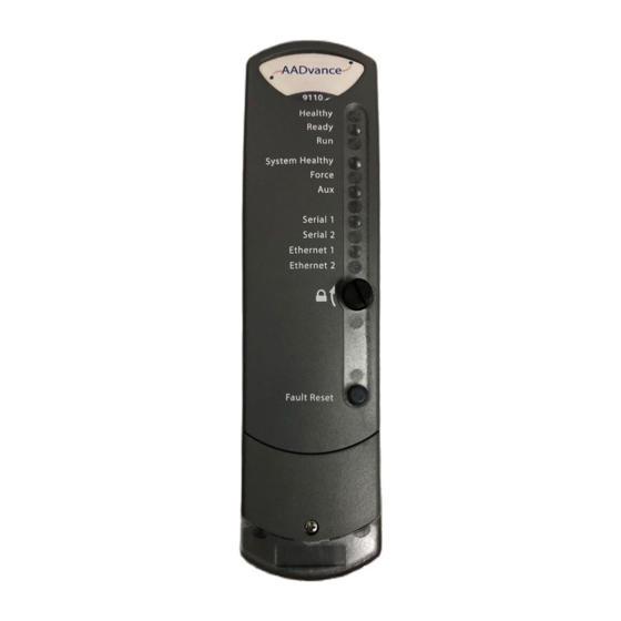
Fault Reset button on the front panel. This feature is provided for systems located in inaccessible locations. Refer to the AADvance Configuration Guide Doc No: ICSTT-RM458 for Workbench 2.x; regarding instructions on how to set up the variable. Rockwell Automation Publication ICSTT-RM447M-EN-P - July 2019... -
Page 46: Controller Internal Bus Structure
Each I/O module has a dedicated response line which returns to the processor. The unique response line for each I/O module supplies an unambiguous identification of the source of the I/O data and assists with fault containment. Rockwell Automation Publication ICSTT-RM447M-EN-P - July 2019... -
Page 47: On-Line Updates I/O Configuration Changes
You can insert a new I/O module into the spare slot and restore a failed channel without interrupting the operation of the other channels. TIP Configure this "hot swap" arrangement when you configure your system at installation and set up time. Rockwell Automation Publication ICSTT-RM447M-EN-P - July 2019... -
Page 48: Processor Firmware Upgrades
AADvance Ethernet ports are used to support several transport layer services; these services are listed in the following table: Protocol Port Number Purpose MODBUS Slave 1132 ISaGRAF, application downloads, debug, SoE 10001-10006 Transparent Communication Interface (Serial Tunnelling) Rockwell Automation Publication ICSTT-RM447M-EN-P - July 2019... -
Page 49: The Aadvance Workbench And Software Development Environment
Key when it is removed protects the application from unauthorized access. The development environment includes: • tools for program development • program documentation • function block library management • application archiving • database configuration • import/export utilities • on-line monitoring Rockwell Automation Publication ICSTT-RM447M-EN-P - July 2019... -
Page 50: Operating Systems (32 Or 64 Bit)
NOTE If the application is Workbench 1.3 and adopts the USB dongle licensing option the workstation PC will require one free USB port. • Network port (10/100 Base T Ethernet), for communications with the controller Rockwell Automation Publication ICSTT-RM447M-EN-P - July 2019... -
Page 51: Importing And Exporting Data
A demo license is supplied free of charge for a first installation on a computer. You change the demo license to a single controller license or a full license by purchasing an unlock code from Rockwell Automation, and entering the code into the software. When you use the demo license, the AADvance Workbench displays a Demo License window each time you try to open a project. - Page 52 Chapter 2 The AADvance Safety Controller Rockwell Automation Publication ICSTT-RM447M-EN-P - July 2019...
-
Page 53: Controller Functionality
An AADvance controller adopts a default value for the PST = 2500 ms which can be adjusted to meet your system requirements by using the following simple equation: where PSTeuc is the process safety time for the equipment under control. Rockwell Automation Publication ICSTT-RM447M-EN-P - July 2019... -
Page 54: Sntp
DINT following a single bit BOOL will start on a new 4 byte boundary. Also: • A LINT Must ALWAYS align on a 64 bit (8byte) boundary. • Any UDT that contains a LINT must ALWAYS be of a size that is divisible by 8 bytes Rockwell Automation Publication ICSTT-RM447M-EN-P - July 2019... -
Page 55: Hart
Network manages all of the sending and receiving of data. It schedules the sending and receiving of data, sending the diagnostic data, managing the safety response if Rockwell Automation Publication ICSTT-RM447M-EN-P - July 2019... - Page 56 The network configuration is dependent on the applications safety and availability requirements. The giving and receiving of data occurs independently from the physical network configuration as the connection between the controllers is treated as a logical network Rockwell Automation Publication ICSTT-RM447M-EN-P - July 2019...
-
Page 57: Serial Communication Interface
MODBUS commands. You can use MODBUS RTU with point-to-point and multi-drop serial links, and MODBUS TCP with Ethernet. NOTE The AADvance controller does not support the MODBUS ASCII protocol. Rockwell Automation Publication ICSTT-RM447M-EN-P - July 2019... -
Page 58: Modbus Master Hardware And Physical Connections
The physical communication ports are located on the 9100 Processor Base Unit. You do not need to add any other hardware to the AADvance controller apart from other components to make the physical connections to the Rockwell Automation Publication ICSTT-RM447M-EN-P - July 2019... -
Page 59: Controller Ip Address
You must set up the IP address data when you create a new system, or if you fit a new processor base unit. Rockwell Automation Publication ICSTT-RM447M-EN-P - July 2019... -
Page 60: Recovery Mode
TCP negotiation (this is the 3-way handshake, RFC 793). You can specify this behavior when you set up DiffServ. IMPORTANT The DiffServ feature is only available with release 1.3 onwards of the AADvance Workbench and controller. Rockwell Automation Publication ICSTT-RM447M-EN-P - July 2019... -
Page 61: Serial Tunneling
E1-2 to E1-1. Similarly (if fitted), the processor module in the second position in the 9100 processor base unit forwards traffic from port E2-1 to E2-2, and from port E2-2 to E2-1. The third processor module (if Rockwell Automation Publication ICSTT-RM447M-EN-P - July 2019... -
Page 62: Compiler Verification Tool
HMIs and SCADA systems, to connect to one or more AADvance controllers to access process data. It conforms to version 1.10 of the Alarms and Events Standard published by the OPC Foundation. Rockwell Automation Publication ICSTT-RM447M-EN-P - July 2019... -
Page 63: Aadvance System Architectures
The processor will operate in 1oo2D under no fault conditions, will degrade to 1oo1D on the first fault in either processor module and will fail-safe when there are faults on both processor modules. Rockwell Automation Publication ICSTT-RM447M-EN-P - July 2019... -
Page 64: Sil 2 Fault Tolerant Input Architectures
NOTE Simplex output modules used for energize to action applications can only be used for low demand applications. Rockwell Automation Publication ICSTT-RM447M-EN-P - July 2019... -
Page 65: Sil 2 Fault Tolerant Output Architecture
Digital Output For digital output modules the following applies: • If the required safe state is ON, you must use dual digital output modules for High Demand applications. Rockwell Automation Publication ICSTT-RM447M-EN-P - July 2019... -
Page 66: Sil 2 Fault Tolerant Input And Sil 2 High Demand Architecture
High demand energize to action applications will require dual output modules. (Analogue Output Modules where the normal output current is less than 4 mA are classed as energize to action applications). Rockwell Automation Publication ICSTT-RM447M-EN-P - July 2019... -
Page 67: Sil 3 Architectures
1oo1D on the first detected fault, the system must be restored to at least 1oo2D by replacing the faulty processor module within the MTTR assumed in the PFD calculations or all SIL 3 safety instrumented function and high demand safety instrumented functions must be shut down. Rockwell Automation Publication ICSTT-RM447M-EN-P - July 2019... -
Page 68: Sil 3 Fail-Safe I/O, Fault Tolerant Processor
PFD calculation. This rule applies to simplex analogue output modules where the safe state is less than or equal to 4 mA and to dual analogue output modules where the safe state is more than 4 mA. Rockwell Automation Publication ICSTT-RM447M-EN-P - July 2019... -
Page 69: Sil 3 Fault Tolerant I/O Architectures
1oo2D under no fault conditions, degrade to 1oo1D on the detection of the first fault in either module and fail- safe when there are faults on both modules. Rockwell Automation Publication ICSTT-RM447M-EN-P - July 2019... -
Page 70: Sil 3 Tmr Input And Processor, Fault Tolerant Output
1oo2D on detection of the first fault in any module, and degrade to 1oo1 on the detection of faults in any two modules and will fail-safe when there are faults on all three modules. Rockwell Automation Publication ICSTT-RM447M-EN-P - July 2019... - Page 71 NOTE All configurations that use dual or triplicate processor modules are applicable for SIL 3 architectures with de-energize to trip outputs. Dual outputs are always required for SIL 3 energize to action outputs. Rockwell Automation Publication ICSTT-RM447M-EN-P - July 2019...
-
Page 72: Certified Configurations
SIL 3 with 1, 2 or 3 modules fitted. Note: When the integrity level is at 1oo1D then the faulty module must be replaced within the MTTR assumed for the PFD calculations to restore the integrity level back to 1oo2D. Rockwell Automation Publication ICSTT-RM447M-EN-P - July 2019... -
Page 73: Example Architectures With Approved Modules
To these can be added I/O modules for redundant and/or fault tolerant configurations based on the following arrangements: • Input modules in simplex, dual and triple modular redundant formations Rockwell Automation Publication ICSTT-RM447M-EN-P - July 2019... - Page 74 Figure 11 - Example SIL 3 with Dual Input and Output Modules An AADvance system can mix different I/O architectures within one controller — for example simplex and dual input modules with dual processor Rockwell Automation Publication ICSTT-RM447M-EN-P - July 2019...
-
Page 75: Simplex I/O Architecture
Figure 12 - Low Demand SIL 2 Architecture System This example supports 8 field inputs and 8 outputs. There is space for one more processor module and one more I/O module. To expand the I/O Rockwell Automation Publication ICSTT-RM447M-EN-P - July 2019... - Page 76 SIL 2 outputs which do not need the additional fault tolerance offered by dual and triple modular redundant configurations. The possibilities for expansion are the same as those for the SIL 2 controller. Rockwell Automation Publication ICSTT-RM447M-EN-P - July 2019...
-
Page 77: Dual Architecture For Fault Tolerant Applications
(as for the previous example) while the second input module supplies fault tolerance for the inputs. A SIL 3 fault tolerant processor and I/O is achieved by dual input and output module configurations with dual or triple processor modules. Rockwell Automation Publication ICSTT-RM447M-EN-P - July 2019... - Page 78 The subsequent example shows how to supply 16 inputs and 16 outputs (this could also be 32 inputs if 16 channel input modules are used). The outputs shown are digital output modules. Rockwell Automation Publication ICSTT-RM447M-EN-P - July 2019...
-
Page 79: Triple Modular Redundant Architecture
This is why the triple modular redundant implementation has a configuration that is inherently better than a typical 2oo3 voting system. Rockwell Automation Publication ICSTT-RM447M-EN-P - July 2019... - Page 80 8-channel modules for 16 inputs and 16 outputs could be arranged like this. For 16 channel TMR input you must use the T9402 16 channel digital input modules in the same arrangement. Rockwell Automation Publication ICSTT-RM447M-EN-P - July 2019...
-
Page 81: Mixed Architectures
It is straightforward to make dual and triple I/O controller architectures. A Mixed Architectures system can have a mixed level of redundancy, fault tolerance and safety integrity levels to meet your business application needs without over-specifying the I/O. Rockwell Automation Publication ICSTT-RM447M-EN-P - July 2019... -
Page 82: Mixed I/O Architectures
SIL 3 energize to trip outputs alongside SIL 2 outputs. The following example shows how a small a viable controller for mixed integrity levels can be when built from AADvance modules. There are 16 Rockwell Automation Publication ICSTT-RM447M-EN-P - July 2019... - Page 83 Chapter 4 inputs (or 32), two duplicated 8 channel inputs (or duplicated 16 channel versions), and two groups of 8 outputs (one dual, one simplex) for field devices. Figure 20 - Mixed Safety System Rockwell Automation Publication ICSTT-RM447M-EN-P - July 2019...
-
Page 84: Distributed Architectures
AADvance is designed to support a distributed safety architecture. Using an SNCP network a SIL 3 architecture can be maintained across multiple controllers by sharing safety data over an Ethernet network shown in the example below: Figure 21 - Distributed Safety Architecture Rockwell Automation Publication ICSTT-RM447M-EN-P - July 2019... -
Page 85: Example Distributed Controller Systems
8000 Series Trusted controller here in a role which uses a large quantity of field devices. The 8000 Series Trusted controller is fully integrated into the system and shares the applications with the AADvance controllers. Rockwell Automation Publication ICSTT-RM447M-EN-P - July 2019... -
Page 86: Typical Network Applications
A usual distributed AADvance system uses two networks: • An information network, which supplies connectivity to the BPCS (basic process control system) and to OPC devices • A dedicated safety network, which handles data shared between the AADvance controllers Rockwell Automation Publication ICSTT-RM447M-EN-P - July 2019... -
Page 87: Controller External Network Connectors
Controller External Network Connectors The controller features six auto-sensing 10/100BASE-TX Ethernet ports which let it to connect to a local area network through standard RJ45 Ethernet cable. There are two ports for each processor module. Rockwell Automation Publication ICSTT-RM447M-EN-P - July 2019... -
Page 88: Specifying A Safety Network
To do this, make sure the network has no single point of failure, refer to the AADvance Safety Manual (Document: ICSTT-RM446) for further details about specifying a safety Network. Rockwell Automation Publication ICSTT-RM447M-EN-P - July 2019... -
Page 89: Aadvance Scalability
The maximum number of simplex I/O channels is limited only by the selection of modules. For example, 16 x 16 Channel input modules and 32 x 8 Channel output modules, equals a maximum of 512 channels. Rockwell Automation Publication ICSTT-RM447M-EN-P - July 2019... -
Page 90: Dual I/O Channel Capacity
8 = 192 I/O channels. This can, for example, be 64 digital inputs, 64 analogue inputs and 64 digital outputs, or any combination of these values with a granularity of eight, the capacity of one I/O module. Rockwell Automation Publication ICSTT-RM447M-EN-P - July 2019... -
Page 91: Triple Modular Redundant Channel Capacity
T9300 I/O base units and modules when you expand the controller. However, if you haven't configured spare slots for new hardware you can still expand your system. You can install the new hardware and change the Rockwell Automation Publication ICSTT-RM447M-EN-P - July 2019... -
Page 92: On-Line Updates I/O Configuration Changes
• The right-hand connector (specified I/O bus 1 in the project tree configuration) mates with a connector on the T9300 I/O base unit. I/O bus 1 supports a maximum of eight I/O base units and 24 I/O modules. Rockwell Automation Publication ICSTT-RM447M-EN-P - July 2019... -
Page 93: Redundancy And Fault Tolerance
I/O and use it in a simplex, dual or triple redundant arrangement. The AADvance controller, therefore, gives an economical solution for redundancy and fault tolerance expansion. You can install the termination Rockwell Automation Publication ICSTT-RM447M-EN-P - July 2019... -
Page 94: Expansion Using Distributed Controllers
You can expand an AADvance system by adding more controllers to create a distributed system. The AADvance Discover (Discovery and Configuration Controllers utility) enables you to connect to external controllers. IMPORTANT The recommended maximum size of a typical distributed AADvance system is 20 controllers. Rockwell Automation Publication ICSTT-RM447M-EN-P - July 2019... -
Page 95: Specifying A New Controller
• Do you need a "hot swap" feature for any channels All of these items must be assessed and known for the specified plant and the intended application. Define a New System The charts use minimal designs to illustrate solutions. Rockwell Automation Publication ICSTT-RM447M-EN-P - July 2019... - Page 96 Chapter 6 Specifying a New Controller Rockwell Automation Publication ICSTT-RM447M-EN-P - July 2019...
- Page 97 Specifying a New Controller Chapter 6 Rockwell Automation Publication ICSTT-RM447M-EN-P - July 2019...
- Page 98 Chapter 6 Specifying a New Controller Rockwell Automation Publication ICSTT-RM447M-EN-P - July 2019...
-
Page 99: Specify I/O Base Units
T9802 termination assemblies — one for each pair of modules • Four T9401 digital input modules used for simplex inputs need four T9801 termination assemblies — one for each module Rockwell Automation Publication ICSTT-RM447M-EN-P - July 2019... -
Page 100: Estimate Aadvance Controller Weight
It is highly recommended that module supply power and field loop power consumption calculations are done to find out the heat dissipation before designing a suitable enclosure and making a decision about the installation environment (see topic "System Design for Heat Dissipation"). Rockwell Automation Publication ICSTT-RM447M-EN-P - July 2019... -
Page 101: Specifying An Enclosure
The enclosure must also be able to handle the heat dissipated by the modules and other components/devices included in the same enclosure. Rockwell Automation Publication ICSTT-RM447M-EN-P - July 2019... -
Page 102: Maximum Enclosure Air Temperature
60664-1: 2007 ATTENTION: Un système AADvance doit être installé dans une enceinte normalisée IP 54 si l’ e nvironnement est classé en degré de pollution 2 conformément à la norme CEI 60664-1: 2007 Rockwell Automation Publication ICSTT-RM447M-EN-P - July 2019... -
Page 103: Enclosure Requirements For A Hazardous Environment - Class I, Division 2, Groups A, B, C And D
IEC 60664-1. • Subject devices are to use conductors with a minimum conductor temperature rating of 85 °C. • Subject devices are to be installed in the vertical orientation only. Rockwell Automation Publication ICSTT-RM447M-EN-P - July 2019... - Page 104 équivalente WARNING: Substitution of any component may impair suitability for Class I, Division 2 or equivalent. AVERTISSEMENT: La substitution de composants peut rendre impropre à l’utilisation en Classe I, Division 2 ou équivalente. Rockwell Automation Publication ICSTT-RM447M-EN-P - July 2019...
-
Page 105: Estimate Heat Dissipation
T9432 Analogue Input Module, 16 channel × 4.0 W (13.6 BTU/hr.) T9451 Digital Output Module, 24 Vdc, 8 channel × 3.0 W (10.2 BTU/hr.) T9482 Analogue Output Module, 8 channel, isolated × 3.6 W (12.3 BTU/hr.) Total: Rockwell Automation Publication ICSTT-RM447M-EN-P - July 2019... -
Page 106: Backplane Electrical Ratings
Input: 0-32 Vdc @ 6.5 mA 9431 18-32 Input: 0-32 Vdc @ 6.5 mA 9432 18-32 Input: 18-32 Vdc @ 24 mA 9481 18-32 Output: 18-32 Vdc/0-20 mA 9482 18-32 Output: 18-32 Vdc/0-20 mA Rockwell Automation Publication ICSTT-RM447M-EN-P - July 2019... -
Page 107: System Power Requirements
Power Arrangements for Field Devices Output modules use an external source of power for field devices. This may be the power source used for the controller or a separate power source. Rockwell Automation Publication ICSTT-RM447M-EN-P - July 2019... -
Page 108: Power Supply And Power Distribution Requirements
Power Distribution Protection The power distribution circuit for each field input and for each output module must be protected, externally to the controller. Rockwell Automation recommend that power distribution must meet national and local panel wiring protection standards. Digital Output Field Power... -
Page 109: Estimating Power Consumption
"Field Loop Power Heat Dissipation". The field power requirements should be calculated separately and is dependent on the number and type of field elements. Refer to the specifications for the Digital and Analogue output modules for details of the channel output electrical specifications. Rockwell Automation Publication ICSTT-RM447M-EN-P - July 2019... - Page 110 Chapter 6 Specifying a New Controller Rockwell Automation Publication ICSTT-RM447M-EN-P - July 2019...
-
Page 111: Module Overview And Specifications
The new processor module automatically carries out self-education and synchronizes with the other processors. Fault detection and fail-over in redundant processor configurations is automatic and has no impact on controller operation. Rockwell Automation Publication ICSTT-RM447M-EN-P - July 2019... -
Page 112: T9110 Processor Module Specification
Safety Requirements Specification (SRS) and documented in operating procedures, the application program must be designed to shut down safety instrumented functions if a module failure due to dangerous fault has not been replaced within the MTTR. Rockwell Automation Publication ICSTT-RM447M-EN-P - July 2019... -
Page 113: T9100 Processor Base Unit
BUSP component that is installed during manufacture. This allows you to remove a faulty processor module and install a new one without needing to set up the IP address of the replacement module. Rockwell Automation Publication ICSTT-RM447M-EN-P - July 2019... - Page 114 Chapter 7 Module Overview and Specifications Figure 27 - Processor base unit Rockwell Automation Publication ICSTT-RM447M-EN-P - July 2019...
-
Page 115: T9100 Base Unit Specification
(12 AWG); Stripping length 7 mm (9/32 in.) Not used Connector for the Program Enable Key Mechanical Specification Dimensions (height × width × depth) 235 mm x 126 mm (9 1/4 in. x 5 in.) Weight 460g (16 oz.) Rockwell Automation Publication ICSTT-RM447M-EN-P - July 2019... -
Page 116: T9300 I/O Base Unit (3 Way)
DIN rail mountings, and holes for screw fixing. It contains a passive backplane that supplies the electrical connections between the I/O modules and the T9100 processor base unit; i.e. the command and response buses and the system power. Rockwell Automation Publication ICSTT-RM447M-EN-P - July 2019... - Page 117 Module Overview and Specifications Chapter 7 Figure 28 - I/O Base Unit Rockwell Automation Publication ICSTT-RM447M-EN-P - July 2019...
- Page 118 I/O base unit. Adjacent base units clip together and are held in position by a plastic retaining clip. Alternatively rows of I/O base units can be connected together using a T9310 expansion cable assembly. Rockwell Automation Publication ICSTT-RM447M-EN-P - July 2019...
-
Page 119: T9300 Base Unit Specification
The expansion cable offers the following features: • Two meter cable length • Secured with retaining screws and screw cap screws • Connects all command and response signals and system power • Screened to decrease resonance emissions Rockwell Automation Publication ICSTT-RM447M-EN-P - July 2019... -
Page 120: T9310 Extension Cable Specification
Redundant System +24 Vdc_1 & 2 power supplies Mechanical Specification Length 2 m (78.74 in.) Weight SCS1-3 Cable Assembly 57 g (2 oz.) Cable Plug Assembly 50 g (2 oz.) Cable Socket 50 g (2 oz.) Rockwell Automation Publication ICSTT-RM447M-EN-P - July 2019... -
Page 121: T9401/2 Digital Input Module, 24 Vdc, 8/16 Channel
Redundant + 24 Vdc nominal; 18 Vdc to 32 Vdc range Module supply power dissipation T9401: 3.3 W (11.3 BTU/hr.) T9402: 4.0 W (13.6 BTU/hr.) Input data voltage range 0V to 32 Vdc Maximum Slew Rate See Figure 30 below Rockwell Automation Publication ICSTT-RM447M-EN-P - July 2019... - Page 122 The input slew may exceed the specified levels providing the duration of the transgression is less than the process safety time of the configured module. Figure 30 - Digital Input Slew Tolerance Rockwell Automation Publication ICSTT-RM447M-EN-P - July 2019...
-
Page 123: T9801/2/3 Termination Assemblies For Digital Inputs
Illustrated is the T9802 dual termination assembly. Figure 31 - Digital/Analogue Input Termination assembly A replaceable fuse protects each channel from field faults. Fuses can be replaced without removing a module or the termination assembly. Rockwell Automation Publication ICSTT-RM447M-EN-P - July 2019... -
Page 124: T9801/2/3 Digital Input Termination Assembly
Input measurement voltage resolution 5 mV, 13 bit Channel isolation T9801 None T9802, T9803: ± 1.5 kVdc maximum withstanding for 1 minute Maximum field loop power dissipation 0.2 W for each field loop (0.68 BTU/hr) Rockwell Automation Publication ICSTT-RM447M-EN-P - July 2019... -
Page 125: T9431/2 Analogue Input Module, 8/16 Channel
Monitoring levels for each input channel are configurable at both the module and channel level. The default parameters are: • Fault: 0 mA to 3.8 mA • Normal: 3.8 mA to 22.0 mA • Fault: > 22.0 mA Rockwell Automation Publication ICSTT-RM447M-EN-P - July 2019... -
Page 126: T9431/2 Analogue Input Module Specification
T9432: 340 g (12 oz.) Casing Plastic, non-flammable SIL 3 is the maximum achievable for a single channel. Selected CPU, input and output voting configurations could increase or decrease the correct SIL achieved. Rockwell Automation Publication ICSTT-RM447M-EN-P - July 2019... -
Page 127: T9831/2/3 Termination Assemblies For Analogue Inputs
16 non-isolated analogue inputs. It supports one T9431 or T9432 analogue input module. The T9832 and T9833 termination assemblies support 16 isolated analogue inputs for dual and triple modular redundant arrangements of analogue input modules. Illustrated is the T9832 termination assembly: Rockwell Automation Publication ICSTT-RM447M-EN-P - July 2019... -
Page 128: Analogue Input Termination Assembly
16; Wiring: Conductor cross section maximum 1.31mm² (16 AWG); Stripping length 6mm (¼ in.) Number of input modules supported T9831 T9832 T9833 Three Electrical Characteristics Input channel fuses 50 mA, 125 V, Type T manufactured by Littelfuse Rockwell Automation Publication ICSTT-RM447M-EN-P - July 2019... -
Page 129: T9451 Digital Output Module, 24Vdc, 8 Channel
• You can disable the line test feature for an output that disables detection of a no-load condition (e.g. for used output channels). Rockwell Automation Publication ICSTT-RM447M-EN-P - July 2019... -
Page 130: T9451 Digital Output Module Specification
SIL 3 is the maximum achievable for a single channel. Selected CPU, input and output voting configurations could increase or decrease the correct SIL achieved. Refer to the Safety Manual for more details. Rockwell Automation Publication ICSTT-RM447M-EN-P - July 2019... -
Page 131: T9851/2 Termination Assemblies For Digital Outputs
T9892 Digital Output Termination Assembly The T9892 Terminal Assembly module operates in conjunction with the T9451 Digital Output Module and provides 8 dual configuration output channels. It shares the same pin-out as the standard AADvance T9852 Digital Rockwell Automation Publication ICSTT-RM447M-EN-P - July 2019... -
Page 132: T9481/2 Analogue Output Module
AADvance where it can be viewed and checked. The module has a user configurable failure mode that can be set outputs to hold last state, fail safe, or a user specified output state. In dual mode the two modules Rockwell Automation Publication ICSTT-RM447M-EN-P - July 2019... -
Page 133: T9481/2 Analogue Output Module Specification
Output current control accuracy at 25 °C 3.9 μΑ, 13-bit Output current monitoring resolution Compliance voltage 3 Vdc to 32 Vdc Maximum Compliance voltage slew rate No limit identified within Compliance voltage range. Rockwell Automation Publication ICSTT-RM447M-EN-P - July 2019... -
Page 134: T9881/2 Termination Assemblies For Analogue Outputs
T9881 132 mm × 42 mm (5-¼ in. × 1-21/32 in.) T9882 13 2mm × 84 mm (5-¼ in. × 3-5/16 in.) Weight T9881 133 g (5 oz.) T9882 260 g (10 oz.) Rockwell Automation Publication ICSTT-RM447M-EN-P - July 2019... -
Page 135: Programming Language Support
This modular construction can help future use of code units. Engineers can debug their own modules independently from each other. Programs can be tried and tested on the computer before downloading to the controller hardware. Rockwell Automation Publication ICSTT-RM447M-EN-P - July 2019... -
Page 136: Support For Variable Types
An engineer can validate a full application off-line, without the target hardware Off-line Simulation and platform. The powerful simulator within the development environment can do Testing structural and functional tests of each module and of the full application. Rockwell Automation Publication ICSTT-RM447M-EN-P - July 2019... -
Page 137: Application (Resource) Program Security
Development stage of development, correcting or prompting the user with the correct use of the language. There is also extensive on-line help, which includes a cross- referenced explanation of the IEC 61131-3 standard. Rockwell Automation Publication ICSTT-RM447M-EN-P - July 2019... - Page 138 Chapter 8 Application (Resource) Development Rockwell Automation Publication ICSTT-RM447M-EN-P - July 2019...
-
Page 139: Controller Mounting
If an expansion cable is to connect to the left-most base unit, the controller also needs space to the left, to fit the expansion cable adapter. Rockwell Automation Publication ICSTT-RM447M-EN-P - July 2019... - Page 140 Chapter 9 System Build This illustration shows the minimum recommended clearances for a flat panel or DIN rail mounting. Rockwell Automation Publication ICSTT-RM447M-EN-P - July 2019...
- Page 141 System Build Chapter 9 The flat panel drilling holes are shown in the illustration: Figure 35 - Flat Panel Mounting Rockwell Automation Publication ICSTT-RM447M-EN-P - July 2019...
-
Page 142: Assemblies Of Base Units
O base units to the left hand side of other I/O base units to install extra rows of I/O base units. Base units are secured in place by top and bottom clips that are inserted into the slots on each base unit. Rockwell Automation Publication ICSTT-RM447M-EN-P - July 2019... - Page 143 I/O buses (the combination of I/O base units and expansion cables) to 8 meters (26.24 ft.). NOTE The 9310 Expansion Cable is 2 m (6.56 ft.). Rockwell Automation Publication ICSTT-RM447M-EN-P - July 2019...
-
Page 144: Controller Power Supply Requirements
WARNING: The power supplies must satisfy the electrical requirements and tests specified in IEC 61131 EN 61010-1 and EN 60950 and must be big enough for the system requirements. Rockwell Automation Publication ICSTT-RM447M-EN-P - July 2019... -
Page 145: Adding Field Cable Management
It is recommended a length of cable trunking or the Management equivalent be put above each set of base units, for cable management. Figure 37 - Field Wiring Connections Rockwell Automation Publication ICSTT-RM447M-EN-P - July 2019... - Page 146 Chapter 9 System Build Rockwell Automation Publication ICSTT-RM447M-EN-P - July 2019...
-
Page 147: Base Units
Analogue output module, 3 channel, isolated T9482 Analogue output module, 8 channel, isolated Special Application Modules Part No. Part Description T9441 Frequency Input Module (Product not yet released. Contact Sales for more information) Rockwell Automation Publication ICSTT-RM447M-EN-P - July 2019... -
Page 148: Termination Assemblies
Backplane expansion cable, 2 meter Blanking Covers Part No. Part Description T9191 Blanking cover (tall) for I/O positions with no TA fitted T9193 Blanking cover (short) for I/O positions with TA or a Processor Rockwell Automation Publication ICSTT-RM447M-EN-P - July 2019... -
Page 149: Spares And Tools
T9905: Polycarbon monofluoride Lithium Coin Battery, BR2032, 20 mm dia; Nominal voltage 3 V; Nominal capacity (mAh) 190; Continuous standard load (mA) 0.03; Operating temperature -30 °C to +80 °C, supplied by Panasonic. Rockwell Automation Publication ICSTT-RM447M-EN-P - July 2019... -
Page 150: Software
IEC 61131 Workbench 2 T9030 OPC portal server T9033 AADvance DTM (for use with HART Pass-Through feature) Demonstration Unit Part No. Part Description T9141 AADvance Demonstration Unit (Including HMI) Miscellaneous Items Part No. Part Description Rockwell Automation Publication ICSTT-RM447M-EN-P - July 2019... -
Page 151: Rockwell Automation Publication Icstt-Rm447M-En-P - July
Chapter Additional Resources For more information about the AADvance system refer to the related Rockwell Automation technical manuals shown in this document map. Resource Document Number Safety Manual ICSTT - RM446 System Build Manual ICSTT - RM448 Configuration Guide ICSTT - RM405... -
Page 152: Regional Offices
(11th Street) PO Box 45235 Abu Dhabi Tel: +65 6622 4888 Tel: +971 2 694 8100 Tel: +971 4 883 7070 Fax: +65 6622 4884 Internet: http://www.rockwellautomation.com/icstriplex Technical support: icstsupport@ra.rockwell.com Sales enquiries: sales@icstriplex.com Rockwell Automation Publication ICSTT-RM447M-EN-P - July 2019... -
Page 153: Glossary
An example is ASCII over RS-232-C. See also 'RS-232-C, RS-422, RS-485' . availability The probability that a system can do its specified functions when required for use. Normally expressed as a percentage. Rockwell Automation Publication ICSTT-RM447M-EN-P - July 2019... - Page 154 A group of conductors for related data. Typically allocated to address, data and control functions in a microprocessor-based system. bus arbitration A mechanism for deciding which device has control of a bus. Rockwell Automation Publication ICSTT-RM447M-EN-P - July 2019...
- Page 155 Glossary CIP Common Industrial Protocol. A communications protocol created by Rockwell Automation for the Logix controller family, and supported by the AADvance controller. AADvance controllers use the protocol to send data to and from Logix controllers using a consumer/producer model. It can also be used to communicate data between AADvance controllers.
- Page 156 The momentary action push switch on the front panel of the 9110 processor module. fault tolerance The ability of a system to operate correctly with a specified number of hardware and software faults. Rockwell Automation Publication ICSTT-RM447M-EN-P - July 2019...
- Page 157 For more details about HART devices refer to the HART Application Guide, created by the HART Communication Foundation, and the full HART specifications. You can download documents from www.hartcomm.org. Rockwell Automation Publication ICSTT-RM447M-EN-P - July 2019...
- Page 158 An IEC 61131 language, almost the same as the simple textual language of PLCs. See 'limited variability language' . integer A variable type specified by the IEC 61131 standard. IXL ISaGRAF eXchange Layer. The protocol for communications between ISaGRAF-based components. Rockwell Automation Publication ICSTT-RM447M-EN-P - July 2019...
- Page 159 The AADvance latch mechanism seen on the front panel of each module and operated by a broad, flat-blade screwdriver. Uses a cam action to hold the module to its base unit. Rockwell Automation Publication ICSTT-RM447M-EN-P - July 2019...
- Page 160 The application execution engine of the AADvance controller, housed in a self- contained and standardized physical enclosure. producer A controller producing a tag to one or more consumers. The controller produces a tag when a consumer asks for one. Rockwell Automation Publication ICSTT-RM447M-EN-P - July 2019...
- Page 161 RTC Real-time clock. RTU Remote terminal unit. The MODBUS protocol supported by the AADvance controller for MODBUS communications over serial links, with the ability to multi-drop to multiple slave devices. Rockwell Automation Publication ICSTT-RM447M-EN-P - July 2019...
- Page 162 To synchronize the sending and receiving machines, a clocking signal is sent by the transmitting computer. There are no start or stop bits. Rockwell Automation Publication ICSTT-RM447M-EN-P - July 2019...
- Page 163 In quality assurance, approval that the product conforms to the specifications. voting system A redundant system (m out of n) requiring at least m of the n channels to be in agreement before the system can take action. Rockwell Automation Publication ICSTT-RM447M-EN-P - July 2019...
- Page 164 The maximum voltage level that can be applied between circuits or components without causing a failure of the insulation. word A 16-bit unsigned value from 0 to 65535. One of the IEC 61131 types. See also 'integer' Rockwell Automation Publication ICSTT-RM447M-EN-P - July 2019...
- Page 165 How Are We Doing? form at http://literature.rockwellautomation.com/idc/groups/literature/documents/du/ra-du002_-en-e.pdf. Rockwell Automation maintains current product environmental information on its website at http://www.rockwellautomation.com/rockwellautomation/about-us/sustainability-ethics/product-environmental-compliance.page. AADvance, Allen-Bradley, ControlFLASH, ControlLogix, ICS Triplex, Rockwell Software, Rockwell Automation, TechConnect, and Trusted are trademarks of Rockwell Automation, Inc. CIP is a trademark of ODVA, Inc.
Need help?
Do you have a question about the Allen-Bradley AADvance T9110 and is the answer not in the manual?
Questions and answers