Table of Contents
Advertisement
Quick Links
AADvance
The Next Step in Automation
System Build Manual
System Build Manual
System Build Manual
System Build Manual
AADvance Controller
Issue: 08
Issue: 08
Issue: 08
Issue: 08
DOCUMENT: 553632
DOCUMENT: 553632
DOCUMENT: 553632
DOCUMENT: 553632
( ( ( ( ICSTT
ICSTT- - - - RM448_EN_P
RM448_EN_P) ) ) )
ICSTT
ICSTT
RM448_EN_P
RM448_EN_P
Advertisement
Table of Contents

Subscribe to Our Youtube Channel
Related Manuals for Rockwell Automation ics triplex AADvance


Summary of Contents for Rockwell Automation ics triplex AADvance
- Page 1 AADvance The Next Step in Automation AADvance Controller System Build Manual System Build Manual System Build Manual System Build Manual Issue: 08 Issue: 08 Issue: 08 Issue: 08 DOCUMENT: 553632 DOCUMENT: 553632 DOCUMENT: 553632 DOCUMENT: 553632 ( ( ( ( ICSTT ICSTT- - - - RM448_EN_P RM448_EN_P) ) ) ) ICSTT...
- Page 2 System Build Manual (AADvance Controller) This page intentionally left blank Document: 553632 (ICSTT-RM448_EN_P) Issue: 08:...
- Page 3 Notice Notice In no event will Rockwell Automation be responsible or liable for indirect or consequential damages resulting from the use or application of this equipment. The examples given in this manual are inluded solely for illustrative purposes. Because of...
- Page 4 System Build Manual (AADvance Controller) Issue Record Issue Record Issue Record Issue Record Issue Date Comments April 2008 First Issue Feb 2009 Update for Product Titles Nov 2009 Update for Release 1.1 July 2010 Update for Release 1.1.1 Oct 2010 Updates for UL Certification March 2011 Updated for Release 1.2...
- Page 5 Notes and Symbols used in this manual Notes and Symbols used in this manual Notes and Symbols used in this manual Notes and Symbols used in this manual This symbol calls attention to items which "must" be considered and implemented when designing and building an AADvance controller for use in a Safety Instrumented Function (SIF).
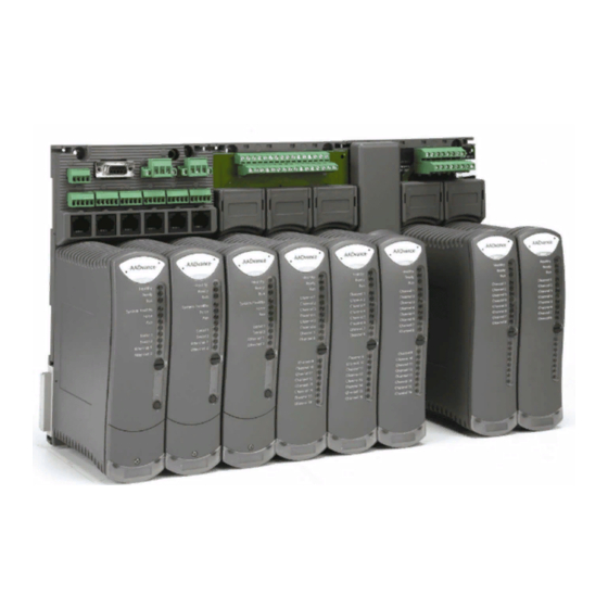
- Page 6 System Build Manual (AADvance Controller) Foreword Foreword Foreword Foreword The AADvance controller is a logic solver consisting of one or more processors and a family of I/O modules. An AADvance system can be built from one or more AADvance controllers and/or standard controllers. This technical manual describes how to assemble a system, switch on and validate the operation of a controller.
-
Page 8: Table Of Contents
System Build Manual (AADvance Controller) Contents Contents Contents Contents Chapter 1 Chapter 1 Chapter 1 Chapter 1 Product Overview ................... 1-1 The AADvance Controller ..........................1-1 Controller TUV Certification ........................1-3 Certification for use in Hazardous Environments ................1-4 KCC-EMC Registration ..........................1-6 AADvanceDiscover Utility ........................ - Page 9 Chapter 3 Chapter 3 Chapter 3 Chapter 3 Install the AADvance System..............3-1 Unpacking and Pre-assembly Checks ......................3-1 Install Base Units and termination Assemblies: Enclosure DIN Rail Assembly Method ....3-2 Allocations of Coding Pegs ........................3-4 Install Base Units and Termination Assemblies: Flat Panel Assembly ........... 3-4 Allocations of Coding Pegs ........................
- Page 10 System Build Manual (AADvance Controller) Upgrade the Processor Module Recovery Mode Firmware ............4-14 Stage 2: Installing the ControlFLASH Firmware Kit for OS, FPGA, LSP and BUSP ....4-19 Upgrade Processor OS, FPGAFPGA, LSP and BUSP Firmware ............. 4-20 Setting Up the Controller IP Address for AADvance Workbench Communications ....4-24 Controller IP Address Setting .........................
-
Page 11: Chapter 1 Product Overview
Chapter Chapter Chapter Chapter 1 1 1 1 Product Overview Product Overview Product Overview Product Overview This chapter provides an overview of a controller and briefly describes its major components. In This Chapter In This Chapter In This Chapter In This Chapter The AADvance Controller ................ - Page 12 A secure network communications protocol, developed by Rockwell Automation for the AADvance system, permits distributed control using new or existing network infrastructure while ensuring the security and integrity of the data. Individual sensors and actuators can connect to a local controller, minimizing the lengths of dedicated field cabling.
- Page 13 The AADvance controller is developed and built for IEC 61131 compliance and includes support for all five programming languages. Program access is secured by a removable "Program Enable" key. Simulation software lets you prove a new application before reprogramming and downloading, again maximizing system uptime. Controller TUV Ce Controller TUV Ce Controller TUV Ce...
-
Page 14: Certification For Use In Hazardous Environments
System Build Manual (AADvance Controller) Certification for use in Hazardous Environments Certification for use in Hazardous Environments Certification for use in Hazardous Environments Certification for use in Hazardous Environments The AADvance controller has been investigated and approved by UL (UL508) for use as Industrial Control Equipment in a general industrial environment and for use in hazardous locations, Class I, Division 2, Groups A, B, C and D. - Page 15 Document: 553632 (ICSTT-RM448_EN_P) Issue: 08:...
-
Page 16: Kcc-Emc Registration
System Build Manual (AADvance Controller) The AADvance controller has also been evaluated under certificate IECEx UL 12.0032X to the standards IEC 60079-0; (5 Edition) and IEC 60079-15 (4 Edition). [ certificate to be supplied] For a system that is located in a Zone 2 Hazardous environment where ATEX certification is required, all modules should be installed in an ATEX and IECEx Certified, tool accessible IP54 enclosure. -
Page 17: Aadvancediscover Utility
AADvanceDiscover Utility AADvanceDiscover Utility AADvanceDiscover Utility AADvanceDiscover Utility The AADvanceDiscover utility is installed when you install the AADvance Workbench, and appears on the Start menu of the computer. Click on AADvance Discover to start the AADvanceDiscover utility. The AADvanceDiscover utility displays a list of the AADvance controllers on the broadcast network, and reports a status for each one: Configurable Locked... -
Page 18: Physical Features
System Build Manual (AADvance Controller) Physical Features Physical Features Physical Features Physical Features An innovative feature of the AADvance controller is the design of the hardware. Everything fits together easily without any need for inter-module wiring. Environmental Specification Environmental Specification Environmental Specification Environmental Specification The following environmental specification defines the minimum recommended... -
Page 19: Product Dimensions
Operating 0 to 2000m (0 to 6,600 ft.) Storage and Transport 0 to 3000m (0 to 10,000 ft.) This equipment must not be transported in unpressurized aircraft flown above 10,000 ft. Electromagnetic Interference Tested to the following standards: EN 61326- 1:2006, Class A;... -
Page 20: Compact Module Design
System Build Manual (AADvance Controller) Summary of Dimensions Summary of Dimensions Summary of Dimensions Summary of Dimensions Attribute Value Base unit dimensions (H × W × D), approx. 233 × 126 × 18mm (see text) (9-¼ in × 5 × ¾ in) Module dimensions (H ×... -
Page 21: Module Polarization Keying
Base units are moulded from a similar material. Each base unit can be mounted onto standard DIN rails or directly onto a panel or wall. The moldings incorporate slots and clamps for DIN rail mountings, and holes for screw fixing. Module Polarization Keying Module Polarization Keying Module Polarization Keying... -
Page 22: Module Locking Mechanism
System Build Manual (AADvance Controller) Module Locking Mechanism Module Locking Mechanism Module Locking Mechanism Module Locking Mechanism Each module carries a locking mechanism, which secures the module onto its base unit. The locking mechanism is in the form of a clamp screw, visible on the front panel of the module and engaged by a quarter turn of a flat blade screwdriver. - Page 23 Part No: Digital Input Fuses T9901: No 396/TE5 50mA time lag fuse; UL 248-14, 125 V,T Leadfree; manufactured by Littlefuse. Part No: Digital Output Fuses T9902: SMF Omni-Block, Surface Mount Fuse Block 154 010, with a 10A, 125V Fast Acting Fuse, Littlefuse. WARNING FUSE REMOVAL or REPLACEMENT When the controller is installed in a Hazardous environment do not remove or...
-
Page 24: T9100 Processor Base Unit
System Build Manual (AADvance Controller) T9100 Processor Base Unit T9100 Processor Base Unit T9100 Processor Base Unit T9100 Processor Base Unit Every AADvance controller has one T9100 processor base unit. A processor base unit supports one, two or three modules depending on the architecture chosen for the application. -
Page 25: Ethernet, Serial Data And Power Connections
The processor base unit provides the electrical connections between the T9110 processor modules, and the rest of the controller modules and has the following connections: Command and response bus connections for up to 48 I/O modules Inter-processor links Two Ethernet 100 BaseT connectors per processor Two serial data connections per processor Dual +24v System power Ground stud... -
Page 26: Serial Communications
System Build Manual (AADvance Controller) Serial Communications Serial Communications Serial Communications Serial Communications The serial ports (S1-1 & S1-2, S2-1 & S2-2, S3-1 & S3-2) support the following signal modes depending upon use: RS485fd: A four-wire full duplex connection that features separate busses for transmit and receive. - Page 27 The bus and power connections from the processor base unit enter the backplane at the left connector and are routed direct to the module connectors. The backplane provides a connector at the right for the next I/O backplane. The connection to the left of the backplane can connect to a processor base unit or another I/O base unit.
-
Page 28: T9310 Expansion Cable Assembly
System Build Manual (AADvance Controller) T9310 Expansion Cable Assembly T9310 Expansion Cable Assembly T9310 Expansion Cable Assembly T9310 Expansion Cable Assembly The T9310 expansion cable assembly connects a T9300 I/O base unit to another I/O base unit or to the T9100 processor base unit. The assembly consists of a cable, terminated by multi-way plugs, and a pair of adaptors. -
Page 29: Backplane Electrical Ratings
Backplane Electrical Ratings Backplane Electrical Ratings Backplane Electrical Ratings Backplane Electrical Ratings The following are the voltage and current ratings for the Process and I/O backplanes: Module Back-plane Electrical Ratings Input/Output Electrical Ratings Voltage (Vdc) Current (mA) 9100 18-32 10.4A (400mA per slot) 9101 18-32 10.4A (400mA per slot) - Page 30 System Build Manual (AADvance Controller) This page intentionally left blank 1-20 Document: 553632 (ICSTT-RM448_EN_P) Issue: 08:...
-
Page 31: Before You Begin
Chapter Chapter Chapter Chapter 2 2 2 2 Before You Begin Before You Begin Before You Begin Before You Begin This chapter lists important information the reader should consider before starting to build the system. It includes preparatory information necessary for a successful installation. -
Page 32: Test Equipment
System Build Manual (AADvance Controller) Test Equipment Test Equipment Test Equipment Test Equipment The assembly of the system does not require the use of test-equipment, however, the preparation for initial switch on and start up may require the use of a multimeter. An engineering workstation running the Workbench programming software will be needed for communicating with the system, downloading the application software and for monitoring system variables and application logic. - Page 33 Recommended Enclosure for a non Recommended Enclosure for a non Recommended Enclosure for a non Recommended Enclosure for a non- - - - hazardous environment hazardous environment hazardous environment hazardous environment An AADvance system must be installed in a suitable enclosure to maintain a Pollution Degree 2 (IEC 60664-1) environment.
-
Page 34: Free Space Around The Controller
System Build Manual (AADvance Controller) Free Space Around the Controller Free Space Around the Controller Free Space Around the Controller Free Space Around the Controller The controller requires a free space at least 140mm deep (from front to back) between the rear panel of an enclosure and the inside of an enclosure door. If you wish to mount the controller on DIN rails, increase this allowance by the additional depth of the DIN rails. -
Page 35: Din Rails Fitting
DIN R DIN Rails Fitting ails Fitting DIN R DIN R ails Fitting ails Fitting You can install the AADvance controller onto a pair of parallel DIN rails. The DIN rails must be TS35 rail, which is 35mm × 7.5mm standard symmetric rail. Alternatively, you can install the controller onto a flat panel. - Page 36 System Build Manual (AADvance Controller) Base Units, DIN Rail installations and Expansion C Base Units, DIN Rail installations and Expansion Cables ables Base Units, DIN Rail installations and Expansion C Base Units, DIN Rail installations and Expansion C ables ables Base units fit together side by side.
-
Page 37: Adding Cable Management
Adding Cable Management Adding Cable Management Adding Cable Management Adding Cable Management The field, power and other system wiring will be connected to terminals along the top of the base units. It is recommended a length of trunking or similar be located above each set of base units, for cable management. - Page 38 System Build Manual (AADvance Controller) PELV (protected extra-low voltage) is an extra low voltage circuit with a protective partition from other circuits which has a protective earth connection. Thus to meet SELV and PELV requirements the power source must have a safety transformer with a protective partition between the primary and secondary windings so that the windings are galvanically and electrically isolated.
-
Page 39: Power Arrangements For Field Devices
Power Arrangements for Field Devices Power Arrangements for Field Devices Power Arrangements for Field Devices Power Arrangements for Field Devices The input circuits and the output modules of the controller require an external source of power for field devices. This may be the power source used for the controller or a separate power source, depending on the application. -
Page 40: Estimate Aadvance Controller Weight
System Build Manual (AADvance Controller) Total: Note: All figures given are worst-case estimates based upon maximum operating field current and voltages. Estimate AADvance Controller Weight Estimate AADvance Controller Weight Estimate AADvance Controller Weight Estimate AADvance Controller Weight Use the following table to estimate the weight of your system. Table 4: Table 4: Table 4:... -
Page 41: Design Considerations For Electrical Grounding
Design Considerations for Electrical Grounding Design Considerations for Electrical Grounding Design Considerations for Electrical Grounding Design Considerations for Electrical Grounding All applications of the controller will require at least two separate ground (earth) systems: An AC safety ground (sometimes called the 'dirty ground') to protect people in the event of a fault. -
Page 42: Specifying The Workstation Pc
Fuses on the termination assemblies can be replaced so access to the fuses is required. There are no user-serviceable parts inside modules therefore repair is by replacement; defective modules should be returned to Rockwell Automation for investigation and repair. WARNING ELECTRICAL ARCS AND EXPLOSION RISK IN HAZARDOUS... - Page 43 Design Provisions Design Provisions Design Provisions Design Provisions The design of the controller installation should make the following provisions: Clear access to remove and install modules, termination assemblies, base units and security dongle (Program Enable key). Repair of controller modules will be by module replacement.
- Page 44 System Build Manual (AADvance Controller) In addition, it may be appropriate to make the following provisions: A lock on the door of the enclosure, to deter unauthorized access and possible unofficial modifications. Lighting. Utility sockets. 2-14 Document: 553632 (ICSTT-RM448_EN_P) Issue: 08:...
-
Page 45: Install The Aadvance System
If any part of the delivered components has been damaged during shipping, notify the carrier and Rockwell Automation immediately. Damaged goods must be returned Rockwell Automation for repair or replacement (see Warranty and Returns instructions with delivery documentation). Document: 553632... -
Page 46: Install Base Units And Termination Assemblies: Enclosure Din Rail Assembly Method
System Build Manual (AADvance Controller) CAUTION Handling Modules Stored at Extreme Temperatures It is recommended that modules removed from storage should be allowed to normalize their temperature before installation. This is particularly important when modules have been stored at very low temperatures where condensation can occur. - Page 47 Insert the retaining clip on the back of the termination assembly into the slot on the I/O base unit. Press the termination assembly onto the base unit and then slide the assembly upwards as far as it will go. Make sure the retaining tab clips over the printed circuit board to secure the termination assembly in position.
-
Page 48: Allocations Of Coding Pegs
System Build Manual (AADvance Controller) Allocations of Coding Pegs Allocations of Coding Pegs Allocations of Coding Pegs Allocations of Coding Pegs Coding pegs are assigned to each module type as shown in the following table: Application Key A Key B Key C 9100 processor base unit (for 9110 processor module) - Page 49 Use only finger pressure to manipulate and engage the clips. Do not attempt to use a screwdriver or other tool as injury or equipment damage may result. Use two clips for each join. 3) Mark off the panel to locate hole positions for three screws for each base unit. You can place the assembly of base units onto the panel and use the assembly as a template, or refer to the illustration to locate the holes.
-
Page 50: Allocations Of Coding Pegs
System Build Manual (AADvance Controller) Allocations of Allocations of Allocations of Allocations of Coding Pegs Coding Pegs Coding Pegs Coding Pegs Coding pegs are assigned to each module type as shown in the following table: Application Key A Key B Key C 9100 processor base unit (for 9110 processor module) -
Page 51: Connect The Ac Safety Ground Connection
Connect the AC Safety Ground Connection Connect the AC Safety Ground Connection Connect the AC Safety Ground Connection Connect the AC Safety Ground Connection The T9100 processor base unit has a ground stud which must be connected to the AC safety ground. - Page 52 System Build Manual (AADvance Controller) For each power supply connection, do the following: Connect the negative line from the power supply, typically labelled '0V', to the left- hand terminal. Connect the positive line from the power supply, typically labelled '+24V', to the right-hand terminal.
-
Page 53: Power And External Connector Wiring Details
Power and External Connector Wiring Details Power and External Connector Wiring Details Power and External Connector Wiring Details Power and External Connector Wiring Details External connectors for power, serial data, Ethernet data and the application security device are connected to the T9100 Processor base unit. The field connections for I/O data are connected to the Termination Assemblies. -
Page 54: Procedure To Connect Serial Communications Cabling
System Build Manual (AADvance Controller) Procedu Procedu Procedu Procedure to Connect Serial Communications Cabling re to Connect Serial Communications Cabling re to Connect Serial Communications Cabling re to Connect Serial Communications Cabling Connect the serial communications cabling to the six plugs labelled S1-1 through S3-2 on the T9100 processor base unit. - Page 55 Note: Each processor uses the two serial ports above it on the baseplate. Data is not mirrored between ports. Therefore a single processor system has two ports available, a dual processor system has four ports and a triple processor system has six ports available to it.
-
Page 56: System Security
System Build Manual (AADvance Controller) RS485 Half RS485 Half- - - - Duplex Duplex RS485 Half RS485 Half Duplex Duplex The Half -duplex connections should be terminated with the recommended values as shown: System Security System Security System Security System Security Serial networks are closed and local and have limited protocol functionality, therefore, immune to any external attack except local deliberate sabotage. -
Page 57: Connecting Field Wiring
Removable media, such as USB storage devices and CDs, should be virus checked before use within the system. The program enable key (shown below) should be removed from the processor base unit after application download (not applicable to a Euro Controller). -
Page 58: Digital Input Field Loop Circuits
System Build Manual (AADvance Controller) Digital Input Field Loop Circuits Digital Input Field Loop Circuits Digital Input Field Loop Circuits Digital Input Field Loop Circuits Recommended Field Loop Circuits Recommended Field Loop Circuits Recommended Field Loop Circuits Recommended Field Loop Circuits This section contains recommended field loop circuits for line monitoring digital inputs used in Emergency Shutdown or Fire &... - Page 59 The suggested values for R1 and R2 are as follows: R1 = 15K Ω 1%, 1W (maximum power dissipated is 47mW at 26.4V) R2 = 3K9 Ω 1%, 1W (maximum power dissipated is 182mW at 26.4V) Suggested threshold values for both of the above circuits are as follows: Threshold ID Value (mV) Maximum Allowed...
- Page 60 System Build Manual (AADvance Controller) Connections to 9802/9803 Isolated Digital Input TA Connections to 9802/9803 Isolated Digital Input TA — — — — 16 Channel Dual/TMR 16 Channel Dual/TMR Connections to 9802/9803 Isolated Digital Input TA Connections to 9802/9803 Isolated Digital Input TA 16 Channel Dual/TMR 16 Channel Dual/TMR Apply a minimum tightening torque of 0.5 Nm (0.37 ft lb) to the terminal screws.
-
Page 61: Analogue Input Field Loop Circuits
Analogue Input Field l Analogue Input Field loop Circuits oop Circuits Analogue Input Field l Analogue Input Field l oop Circuits oop Circuits These circuits can be used for simplex, dual and triple configurations of analogue input modules. Fit a fuse (as shown) in each circuit to protect the field wiring. Recommended Field Loop Circuits Recommended Field Loop Circuits Recommended Field Loop Circuits... - Page 62 System Build Manual (AADvance Controller) 4 4 4 4 - - - - Wire Analogue Input Wire Analogue Input Wire Analogue Input Wire Analogue Input Connections to T9831 Non Connections to T9831 Non Connections to T9831 Non Connections to T9831 Non- - - - isolated Analogue Input TA isolated Analogue Input TA isolated Analogue Input TA —...
- Page 63 Connections to T9832/T9833 Isolated Analogue Input TA Connections to T9832/T9833 Isolated Analogue Input TA Connections to T9832/T9833 Isolated Analogue Input TA Connections to T9832/T9833 Isolated Analogue Input TA — — — — 16 Channel TMR 16 Channel TMR 16 Channel TMR 16 Channel TMR Apply a minimum tightening torque of 0.5 Nm (0.37 ft lb) to the terminal screws.
- Page 64 System Build Manual (AADvance Controller) Recommended Field Circuit for Digit Recommended Field Circuit for Digit Recommended Field Circuit for Digit Recommended Field Circuit for Digital Outputs al Outputs al Outputs al Outputs This circuit is suitable for simplex and dual configurations of digital output modules. The two 10A fuses shown are included on the termination assembly within the controller.
-
Page 65: Recommended Circuit For Analogue Outputs
Connections to T9851/T9852 Digital Output TA Connections to T9851/T9852 Digital Output TA Connections to T9851/T9852 Digital Output TA Connections to T9851/T9852 Digital Output TA — — — — 8 Channel Simplex/Dual 8 Channel Simplex/Dual 8 Channel Simplex/Dual 8 Channel Simplex/Dual Apply a minimum tightening torque of 0.5 Nm (0.37 ft lb) to the terminal screws. - Page 66 System Build Manual (AADvance Controller) The above circuit is appropriate for devices that are powered by the system. The channel will pass a requested current between 0mA and 24mA. The field device could also be connected between the 24V supply and the Loop Plus terminal. Note: that if the 24V supply is shared between channels or between modules, the field loops will not be isolated from each other.
-
Page 67: Connecting The Aadvance Controller To An Ethernet Network
Note: Apply a minimum tightening torque of 0.5 Nm (0.37 ft lb) to the terminal screws. Connecting the AADvance Controller to an Ethernet Network Connecting the AADvance Controller to an Ethernet Network Connecting the AADvance Controller to an Ethernet Network Connecting the AADvance Controller to an Ethernet Network The T9100 processor base unit has six auto-sensing 10/100BASE-TX Ethernet ports which allow it to connect to a local area network through standard Rj45 Ethernet cable. -
Page 68: Install A T9110 Processor Module
System Build Manual (AADvance Controller) Insta Insta Insta Install Modules ll Modules ll Modules ll Modules The modules of the AADvance controller mount onto the base units. The processor module(s) mount onto the T9100 processor base unit, while the various I/O modules mount onto the T9300 I/O base unit and associated termination assemblies. -
Page 69: Upgrade A Processor Module Firmware
3) The module locking screw requires a quarter turn clockwise to lock. Use a broad (9mm) flat blade screwdriver to lock the locking screw. Note: The locking screw acts as a power interlock device. Therefore, the locking screw must be in the locked position after the power is applied otherwise the module will not boot up. -
Page 70: Set The Processor Clock
System Build Manual (AADvance Controller) (Part No: T9905 Poly-carbonmonofluride Lithium Coin Battery, BR2032 (recommended type) , 20mm dia; Nominal voltage 3V; Nominal capacity (mAh) 190; Continuous standard load (mA) 0.03; Operating temperature -30°C to 80°C, supplied by Panasonic. The battery will last for approximately 10 years under normal operating conditions, or approximately six months if the module is not in use. -
Page 71: Install I/O Modules
4) To control the time setting, wire variables to the RTC Control points: RTC Write RTC Read 5) Wire Variables to RTC Control: Hours Minutes Seconds 6) Set RTC Read to be always True (the time will not be written unless this point is also True). -
Page 72: Install Blanking Covers
System Build Manual (AADvance Controller) Install Blanking Covers Install Blanking Covers Install Blanking Covers Install Blanking Covers Install a blanking cover to each spare position on the base units. Place the blanking cover on the base unit and use a broad (9mm) flat blade screwdriver to turn the clamp screw 90°... -
Page 73: Install T9310 Expansion Cable
Install T9310 Expansion Cable Install T9310 Expansion Cable Install T9310 Expansion Cable Install T9310 Expansion Cable 1) The expansion cable ferrites are snap on components. Fit the ferrites 50mm (1.97) from each end and secure with cable ties either side of the ferrites. Connect Expansion Cable between T9100 Base Unit and T9300 I/O Base unit (IO Bus2) Connect Expansion Cable between T9100 Base Unit and T9300 I/O Base unit (IO Bus2) Connect Expansion Cable between T9100 Base Unit and T9300 I/O Base unit (IO Bus2) - Page 74 System Build Manual (AADvance Controller) Secure the socket assembly by inserting the two M3 socket cap screws. Tighten the screws with a 2.5mm Allen key. Install the cable to the socket assembly and tighten the retaining screws by hand. 2) Insert the free end of the expansion cable into a right hand socket of a T9300 I/O base unit.
- Page 75 Tighten the screws with a 2.5mm Allen key. Install the cable to the plug assembly and tighten the retaining screws by hand. 2) Connect the free end of the expansion cable to the left hand plug of an I/O base unit using a cable socket assembly.
-
Page 76: Fault Reporting Reference Information
System Build Manual (AADvance Controller) Fault Reporting Reference Information Fault Reporting Reference Information Fault Reporting Reference Information Fault Reporting Reference Information Each module has a set of front panel status indicators. The purpose and meaning of these indicators relevant to each module is as follows: Status Indicators on the T94xx Series Input and Output Module Status Indicators on the T94xx Series Input and Output Module Status Indicators on the T94xx Series Input and Output Module... -
Page 77: Status Indicators On The T9110 Processor Module
GREEN Module is online and providing data to/receiving data from application AMBER Module is inserted into a running system but not online. Press the Fault Reset button on any processor module to enable the module to go online Module is ready to go online but no application is running Channel 1 - 8 Provides an indication of the status of each input or output channel Input module: field switch is open... - Page 78 System Build Manual (AADvance Controller) and indicates that the module has no hardware faults. When in the recovery Mode and no faults are present the LED is GREEN Note: 1. If Healthy is GREEN and all the other indicators are OFF then the module has failed to boot up 2.
- Page 79 Force Provides an indication that variables are being locked/forced by the application. The same indication will show for all educated and synchronised processors No power and stays off while the module is booting up (10 to 20 seconds) GREEN No variables are being locked/forced AMBER Module is in the Recovery Mode.
- Page 80 System Build Manual (AADvance Controller) This page intentionally left blank 3-36 Document: 553632 (ICSTT-RM448_EN_P) Issue: 08:...
-
Page 81: Recommendations To Manage Test Documentation
Chapter Chapter Chapter Chapter 4 4 4 4 System Start System Start- - - - Up System Start System Start This chapter describes a structured approach to the start up of a controller system. When the checks and module installation and start up is completed successfully, the system is ready for a Functional Acceptance Test. -
Page 82: System Physical Design Check
System Build Manual (AADvance Controller) System Physical Design Check System Physical Design Check System Physical Design Check System Physical Design Check Assess the physical design of the system to determine whether it is ready to be tested. Do the following: Verify there is physical segregation of any mains supply circuits from the 24V dc controller circuits. -
Page 83: Procedure To Check Power Distribution Integrity
Procedure to check Power Distribution Integrity Procedure to check Power Distribution Integrity Procedure to check Power Distribution Integrity Procedure to check Power Distribution Integrity Note: Before you begin this task, you must have checked the ground bonding. Check the integrity of the power distribution system to verify that each power distribution sub-section is wired in accordance with the drawings and that the subsections are isolated from each other. -
Page 84: Start Up Process
System Build Manual (AADvance Controller) Start Up Process Start Up Process Start Up Process Start Up Process Once the procedures for power distribution tests have been successfully completed, the controller is ready for installation of its modules and its second power up. The installation process should be completed in the following order: 1) Switch off power to the controller —... - Page 85 Step Task Force Will remain OFF as the Module boots up (10 to 20 seconds) then stays OFF until the module has educated. Will remain OFF as the Module boots up (10 to 20 seconds) then is dependent upon data connection. Serial 1 Will remain OFF as the Module boots up (10 to 20 seconds) then is dependent upon data connection...
- Page 86 System Build Manual (AADvance Controller) Table 9: Table 9: Table 9: Table 9: Procedure for Installation of a 2nd and 3rd Processor Procedure for Installation of a 2nd and 3rd Processor Procedure for Installation of a 2nd and 3rd Processor Procedure for Installation of a 2nd and 3rd Processor Note: The second and third processor modules must be programmed with the same firmware as the first processor.
-
Page 87: I/O Module Start Up Process
Step Task When the Run indicator goes AMBER press the Fault Reset button and the processor will display the following indications: Healthy Green Ready GREEN (can flash for a short time as the module educates) AMBER to GREEN (AMBER as the module educates) System Healthy GREEN Force... - Page 88 System Build Manual (AADvance Controller) Ready GREEN AMBER Channel 1 – 8 Press the Fault Reset button on the processor module and the Run indication goes GREEN. The module will now be on-line with the following status indications: Healthy GREEN Ready GREEN GREEN...
- Page 89 If the module fails to educate and go on-line replace the module. Document: 553632 (ICSTT-RM448_EN_P) Issue: 08:...
-
Page 90: Controlflash Firmware Upgrades
ControlFLASH programming tool, along with its required support drivers and on line HELP. Quick Start and RSLinx Classic Lite software or better. To install and configure the ControlFLASH utility refer to the Rockwell Automation ControlFLASH Upgrade Kit documentation, Publication No: 1756-UM105C-EN-E March 2012 available from the Rockwell Automation Literature Library. -
Page 91: Stage 1: Installing The Controlflash Firmware
The RSLinx Classic Lite software must be installed before you can install the ControlFLASH software. RSLinx software is a communications software package that you can use with a wide variety of rockwell automation applications and hardware. The ControlFLASH software uses the RSLinx Classic Lite software to communicate over Data highway Plus, DFI, DH485, ControlNet, DeviceNet and Ethernet networks. - Page 92 System Build Manual (AADvance Controller) 3) Read and agree to the license and click Next 4) Click Browse to select the location of the installation or Next to select the default location. 5) Click Next to start the installation. 4-12 Document: 553632 (ICSTT-RM448_EN_P) Issue: 08:...
- Page 93 ControlFLASH installs. 6) To launch ControlFLASH select the Yes I want to launch controlFLASH option, then click Close. Document: 553632 4-13 (ICSTT-RM448_EN_P) Issue: 08:...
- Page 94 System Build Manual (AADvance Controller) ControlFLASH will launch and you can now upgrade the Processor Module firmware. Upgrade the Processor Module Recovery Mo Upgrade the Processor Module Recovery Mode Firmware de Firmware Upgrade the Processor Module Recovery Mo Upgrade the Processor Module Recovery Mo de Firmware de Firmware This is the recommended procedure to upgrade the processor module firmware using...
- Page 95 2) Click Next. 3) Select T9110 from the list. 4) Browse to the device in the RSLinx window Document: 553632 4-15 (ICSTT-RM448_EN_P) Issue: 08:...
- Page 96 System Build Manual (AADvance Controller) 5) Select the firmware revision for the latest Release. 6) Check the summary details, click Finish 4-16 Document: 553632 (ICSTT-RM448_EN_P) Issue: 08:...
- Page 97 The continue message is displayed: 7) Click Yes to continue with the update A progress bar is displayed When the progress bar reaches the end, it may take several minutes for the next screen to appear. Document: 553632 4-17 (ICSTT-RM448_EN_P) Issue: 08:...
- Page 98 System Build Manual (AADvance Controller) Note: It has not locked up! Wait until the next message box appears ! You may get a "Comms error message" as AADvance processors do not automatically reboot as ControlFLASH expects them to but the firmware download should have completed correctly.
-
Page 99: Stage 2: Installing The Controlflash Firmware Kit For Os, Fpga, Lsp And Busp
10) Click OK and another error message is displayed. 11) Click OK then Cancel to Exit ControlFLASH. 12) Reboot the processor module by switching the power OFF then ON and hold in the Fault Reset button as the module reboots until the Aux LED goes amber. The processor module(s) will reboot into the Recovery Mode indicated by the following LED states on the processor module. -
Page 100: Upgrade Processor Os, Fpgafpga, Lsp And Busp Firmware
System Build Manual (AADvance Controller) Upgrade Processor OS, FPGAFPGA, LSP and BUSP Firmware Upgrade Processor OS, FPGAFPGA, LSP and BUSP Firmware Upgrade Processor OS, FPGAFPGA, LSP and BUSP Firmware Upgrade Processor OS, FPGAFPGA, LSP and BUSP Firmware This procedure describes how to upgrade the processor module firmware using ControlFLASH. - Page 101 4) Browse to the device in the RSLinx window 5) Select the firmware revision for the latest Release. Document: 553632 4-21 (ICSTT-RM448_EN_P) Issue: 08:...
- Page 102 System Build Manual (AADvance Controller) 6) Check the summary details, click Finish The continue message is displayed: 7) Click Yes to continue with the update 4-22 Document: 553632 (ICSTT-RM448_EN_P) Issue: 08:...
- Page 103 A progress bar is displayed Note: if the processor is not in the Recovery Mode the following error is displayed. Follow the procedure in Stage 1 to download the recovery Mode. After the progress bar reaches the end, it may take several minutes for the next screen to appear.
-
Page 104: Setting Up The Controller Ip Address For Aadvance Workbench Communications
Controller IP Address Setting The AADvanceDiscover Utilility uses a discovery and configuration protocol (proprietary to Rockwell Automation) to set the controller IP address within the AADvance Workbench and to scan the broadcast domain for other AADvance controllers. The utility locates each controller by its unique MAC Address. Having located a particular controller to be configured, the utility lets you configure the resource number and IP Address to be stored in the controller;... -
Page 105: About Discover Communications
Double-clicking on an entry in the list lets you inspect the resource and IP address settings for a controller. There is also a Refresh button, which makes a scan of the network and creates a new list. A controller is configurable when the program enable key is present (this plugs into the KEY connector on the processor base unit) and either no application is loaded or an application is loaded but not running. -
Page 106: Configure The Controller Resource Number
System Build Manual (AADvance Controller) 3) Do not use an office network. Use an isolated hub or switch between the computer and AADvance controller. Check that the hub/switch has LEDs lit for the ports to both computer and controller, showing that the ports are working. 4) Open the Network Connections window. -
Page 107: Configure The Ip Address In The Controller
The resource and IP Address dialog box opens. 6) Enter the resource value into the Resource Number field, click Apply. Returning to the main window of the utility, the controller status will show Pending Restart. 7) To complete the update, cycle the power to the controller. 8) Refresh the screen to confirm that the new resource number is displayed in the resource field and the controller status is configurable. - Page 108 System Build Manual (AADvance Controller) 2) Make sure the program enable key is inserted in the KEY connector on the processor base unit. 3) Start the AADvanceDiscover tool from the Start menu: Start → All Programs → AADvance → AADvance Discover. The AADvanceDiscover utility scans the network for controllers, and creates a list.
- Page 109 Returning to the main window of the utility, the controller status will show In Progress and then Configurable. The controller uses the new settings. Document: 553632 4-29 (ICSTT-RM448_EN_P) Issue: 08:...
- Page 110 System Build Manual (AADvance Controller) This page intentionally left blank 4-30 Document: 553632 (ICSTT-RM448_EN_P) Issue: 08:...
-
Page 111: Chapter 5 Functional Acceptance Testing
Chapter Chapter Chapter Chapter 5 5 5 5 Functional Acceptance Testing Functional Acceptance Testing Functional Acceptance Testing Functional Acceptance Testing Functional acceptance testing, also known as factory acceptance testing or integration testing, will test the controller and its associated application software to make sure it satisfies the requirements defined in the requirements specification for an integrated system. - Page 112 System Build Manual (AADvance Controller) Controller Configuration Controller Configuration Controller Configuration Controller Configuration Testing should take place on a defined version of the controller. Record the type, serial number and physical location of module for shipping and later re-installation in their original locations.
-
Page 113: Chapter 6 Dismantling The Aadvance System
Rockwell Automation to discuss the most appropriate way to do this. Re- - - - use Before disposing of serviceable items, contact Rockwell Automation. It may be possible to return unwanted items to Rockwell Automation for possible future reconditioning. Document: 553632... -
Page 115: Chapter 7 Parts List
Chapter Chapter Chapter Chapter 7 7 7 7 Parts List Parts List Parts List Parts List Bases Part No. Part Description T9100 Processor base unit T9300 I/O base unit (3 way) Modules Part No. Part Description T9110 Processor module T9401 Digital input module, 24Vdc, 8 channel, isolated T9402 Digital input module, 24Vdc, 16 channel, isolated... - Page 116 System Build Manual (AADvance Controller) T9831 Analogue input TA, 16 channel, simplex, commoned T9832 Analogue input TA, 16 channel, dual T9833 Analogue input TA, 16 channel, TMR T9851 Digital output TA, 24Vdc, 8 channel, simplex, commoned T9852 Digital output TA, 24Vdc, 8 channel, dual T9881 Analogue output TA, 8 channel, simplex commoned T9882...
- Page 117 T9903 Replacement coding pegs (pack of 20) T9904 Replacement backplane clips (pack of 20) T9905 Replacement processor 3V lithium cell (pack of 20) *see notes T9906 Replacement program enable key T9907 Installation tool kit T9908 Fuse Extractor Tool Software Part No. Part Description T9082U IEC 61131 Workbench, USB key, single user, single controller...
- Page 118 System Build Manual (AADvance Controller) T9902: SMF Omni-Block, Surface Mount Fuse Block 154 010, with a 10A, 125V Fast Acting Fuse, Littlefuse. T9905: Poly-carbonmonofluride Lithium Coin Battery, BR3032, 20mm dia; Nominal voltage 3V; Nominal capacity (mAh) 190; Continuous standard load (mA) 0.03; Operating temperature 30°C to 80°C, supplied by Panasonic Document: 553632 (ICSTT-RM448_EN_P) Issue: 08:...
-
Page 119: Chapter 8 Glossary Of Terms
Glossary of Terms Glossary of Terms Glossary of Terms Glossary of Terms Glossary of Terms A A A A asynchronous asynchronous asynchronous asynchronous accuracy accuracy accuracy accuracy A data communications term describing a serial transmission protocol. A start signal is The degree of conformity of a measure to a sent before each byte or character and a standard or a true value. - Page 120 'CIP over Ethernet/IP', created by A type of variable that can accept only the Rockwell Automation for the Logix values 'true' and 'false'. controller family, and which is also BPCS BPCS BPCS BPCS supported by the AADvance controller.
- Page 121 Chapter 7 Glossary of Terms consumer consumer dictionary dictionary consumer consumer dictionary dictionary The consuming controller requests the tag The set of internal input and output from the producing controller. variables and defined words used in a program. contact contact contact contact discrepancy...
- Page 122 System Build Manual (AADvance Controller) fault reset button fault reset button fault reset button fault reset button function block diagram function block diagram function block diagram function block diagram The momentary action push switch located An IEC 61131 language that describes a on the front panel of the 9110 processor function between input variables and output module.
- Page 123 Chapter 7 Glossary of Terms hot swap hot swap instruction list instruction list hot swap hot swap instruction list instruction list See live insertion. An IEC 61131 language, similar to the simple textual language of PLCs. See 'limited I I I I variability language'.
- Page 124 System Build Manual (AADvance Controller) M M M M manual call point manual call point manual call point manual call point A series of standards specifications which support open connectivity in industrial A component of a fire detection and fire automation.
- Page 125 Chapter 7 Glossary of Terms processor module processor module RS- - - - 232 232- - - - C, RS C, RS- - - - 422, RS 422, RS- - - - 485 processor module processor module C, RS C, RS 422, RS 422, RS The application execution engine of the...
- Page 126 System Build Manual (AADvance Controller) synchronous synchronous synchronous synchronous Safe Failure Fraction. Given by (the sum of A data communications term describing a the rate of safe failures plus the rate of serial transmission protocol. A pre-arranged detected dangerous failures) divided by (the number of bits is expected to be sent across sum of the rate of safe failures plus the rate a line per second.
- Page 127 Chapter 7 Glossary of Terms U U U U U U U U Rack unit. A unit of measure used to describe the height of equipment intended for mounting in a standard rack. Equivalent to 44.45mm (1-¾ inches). V V V V validation validation validation...
- Page 129 Chapter Chapter Chapter Chapter 9 9 9 9 Additional Resour Additional Resources Additional Resour Additional Resour For more information about the AADvance system refer to the associated Rockwell Automation technical manuals shown in this document map. Publication Purpose and Scope Safety Manual This technical manual defines how to safely apply AADvance controllers for a Safety Instrumented Function.
-
Page 130: Regional Offices
Doc No: 553630. Regiona Regiona Regiona Regional Offices l Offices l Offices l Offices Rockwell Automation Oil and Gas Resources are available in Regional Offices worldwide. Rockwell Automation Rockwell Automation Rockwell Automation 4325 West Sam Houston Hall Road Millenium House...
Need help?
Do you have a question about the ics triplex AADvance and is the answer not in the manual?
Questions and answers