
Related Manuals for Rockwell Automation 1766-L32AWA


Summary of Contents for Rockwell Automation 1766-L32AWA
-
Page 1: Table Of Contents
Installation Instructions MicroLogix 1400 Programmable Controllers Catalog Number(s) 1766-L32AWA, 1766-L32AWAA, 1766-L32BWA, 1766-L32BWAA, 1766-L32BXB, 1766-L32BXBA Topic Page Important User Information Additional Resources Overview Controller Description Hazardous Location Considerations Mount the Controller Connect 1762 I/O Expansion Modules Wire the Controller Specifications... -
Page 2: Important User Information
In no event will Rockwell Automation, Inc. be responsible or liable for indirect or consequential damages resulting from the use or application of this equipment. - Page 3 MicroLogix 1400 Programmable Controllers Environment and Enclosure This equipment is intended for use in a Pollution Degree 2 industrial ATTENTION environment, in overvoltage Category II applications (as defined in IEC publication 60664-1), at altitudes up to 2000 meters (6562 ft) without derating. This equipment is considered Group 1, Class A industrial equipment according to IEC/CISPR Publication 11.
- Page 4 MicroLogix 1400 Programmable Controllers North American Hazardous Location Approval The following modules are North American Hazardous Location approved: 1766-L32AWA, 1766-L32AWAA, 1766-L32BWA, 1766-L32BWAA, 1766-L32BXB, 1766-L32BXBA The following information applies when Informations sur l’utilisation de cet operating this equipment in hazardous équipement en environnements...
-
Page 5: Additional Resources
1770-4.1 techniques. If you would like a manual, you can: • download a free electronic version from the internet: http://literature.rockwellautomation.com • purchase a printed manual by contacting your local Allen-Bradley distributor or Rockwell Automation representative Publication 1766-IN001D-EN-P - June 2015... -
Page 6: Overview
MicroLogix 1400 Programmable Controllers Overview MicroLogix 1400 controllers are suitable for use in an industrial environment when installed in accordance with these instructions. Specifically, this equipment is intended for use in clean, dry environments (Pollution degree 2 ) and with circuits not exceeding Over Voltage Category II (IEC 60664-1) . -
Page 7: Controller Description
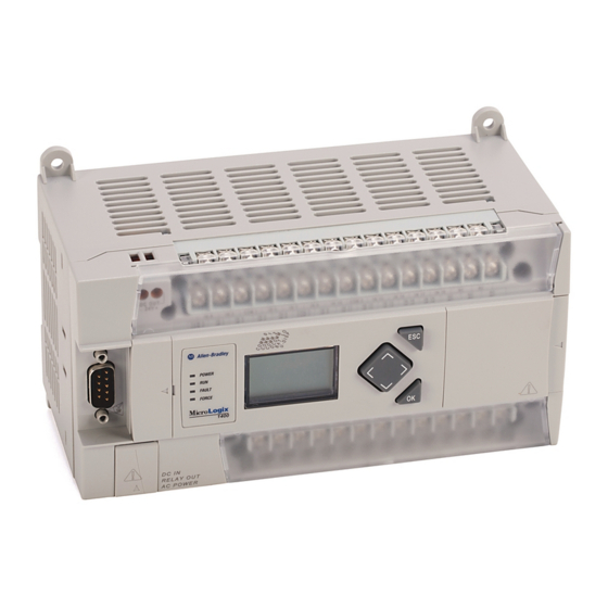
MicroLogix 1400 Programmable Controllers Controller Description 44514 44515 Left side view Top view Description Comm port 2 - 9-pin D-Shell RS-232C connector Memory module (refer to MicroLogix 1400 Memory Module Installation Instructions, publication 1766-IN010 for instructions on installing the memory module). User 24V (for 1766-L32BWA and 1766-L32BWAA only) Input terminal block LCD Display Keypad (ESC, OK, Up, Down, Left, Right) - Page 8 12 Fast 24V DC Inputs 1766-L32BWA 24V DC 8 Normal 24V DC Inputs 12 Relay Outputs 100/240V AC 20 120V AC Inputs 1766-L32AWA 12 Relay Outputs None 12 Fast 24V DC Inputs None 8 Normal 24V DC Inputs 1766-L32BXB 24 V DC...
-
Page 9: Hazardous Location Considerations
MicroLogix 1400 Programmable Controllers Hazardous Location Considerations This equipment is suitable for use in Class I, Division 2, Groups A, B, C, D or non-hazardous locations only. The following WARNING statement applies to use in hazardous locations. EXPLOSION HAZARD WARNING •... - Page 10 MicroLogix 1400 Programmable Controllers Environnements dangereux Cet équipement est conçu pour une utilisation en environnements dangereux de Classe I, Division 2, Groupes A, B, C, D ou non dangereux. La mise en garde suivante s’applique à utilisation en environnements dangereux. DANGER D’EXPLOSION WARNING •...
-
Page 11: Mount The Controller
MicroLogix 1400 Programmable Controllers Mount the Controller General Considerations Most applications require installation in an industrial enclosure to reduce the effects of electrical interference and environmental exposure. Locate your controller as far as possible from power lines, load lines, and other sources of electrical noise such as hard-contact switches, relays, and ac motor drives. - Page 12 MicroLogix 1400 Programmable Controllers Mounting Dimensions 44516 1766-L32BWA, 1766-L32AWA, 1766-L32BXB, 1766-L32BWAA, 1766-L32AWAA, 1766-L32BXBA Dimension Height 90 mm (3.5 in.) 180 mm (7.087 in.) 87 mm (3.43 in.) Controller Spacing The controller mounts horizontally, with the expansion I/O extending to the right of the controller.
- Page 13 MicroLogix 1400 Programmable Controllers DIN Rail Mounting The maximum extension of the latch is 14 mm (0.55 in.) in the open position. A flat-blade screwdriver is required for removal of the controller. The controller can be mounted to EN50022-35x7.5 or EN50022-35x15 DIN rails. DIN rail mounting dimensions are shown below.
- Page 14 MicroLogix 1400 Programmable Controllers Follow these steps to remove your controller from the DIN rail. 1. Place a flat-blade screwdriver in the DIN rail latch at the bottom of the controller. 2. Holding the controller, pry downward on the latch until the latch locks in the open position.
- Page 15 MicroLogix 1400 Programmable Controllers Using the Battery The MicroLogix 1400 controller is equipped with a replaceable battery (catalog number 1747-BA). The Battery Low indicator on the LCD display of the controller shows the status of the replaceable battery. When the battery is low, the indicator is set (displayed as a solid rectangle).
-
Page 16: Connect 1762 I/O Expansion Modules
MicroLogix 1400 Programmable Controllers 2. Secure the battery connector wires so that it does not block the 1762 expansion bus connector as shown below. Battery compartment Battery 1762 I/O expansion bus connector Battery wire connector Battery connector Battery wires twisted pair 44522 Connect 1762 I/O Expansion Modules ATTENTION... -
Page 17: Wire The Controller
MicroLogix 1400 Programmable Controllers 3. Replace the cover as shown below. 44523 The MicroLogix 1400 controller is designed to support up to any seven 1762 expansion I/O modules. For detailed information on using expansion I/O, refer to the installation instructions for your expansion module. - Page 18 OUT10 OUT5 OUT6 OUT9 OUT11 Group 0 Group 1 Group 2 Group 3 Group 4 Group 5 Group 6 44524 Output Terminal Block 1766-L32AWA/L32AWAA Input Terminal Block COM 1 IN10 COM 3 IN13 IN15 IN17 IN19 IV0(+) IV2(+) COM 0...
- Page 19 MicroLogix 1400 Programmable Controllers 1766-L32BXB/L32BXBA Input Terminal Block COM 1 IN10 COM 3 IN13 IN15 IN17 IN19 IV0(+) IV2(+) COM 0 COM 2 IN11 IN12 IN14 IN16 IN18 IV1(+) IV3(+) NEUT OUT0 OUT1 OUT2 OUT4 OUT6 COM 2 OUT8 OUT9 OUT10 VDC2 OUT3...
- Page 20 MicroLogix 1400 Programmable Controllers Output Terminal Grouping Outputs Controller Output Group Description Voltage Terminal Output Terminal 1766-L32AWA Group 0 Isolated relay output VAC/DC0 OUT 0 1766-L32AWAA Group 1 Isolated relay output VAC/DC1 OUT 1 Group 2 Isolated relay output VAC/DC2...
- Page 21 MicroLogix 1400 Programmable Controllers Wiring Recommendation When wiring without spade lugs, keep the finger-safe covers in place. Loosen the terminal screw and route the wires through the opening in the finger-safe cover. Tighten the terminal screw, making sure the pressure plate secures the wire. Finger-safe cover 44527 ATTENTION...
- Page 22 MicroLogix 1400 Programmable Controllers Spade Lug Recommendation The diameter of the terminal screw head is 5.5 mm (0.220 in.). The input and output terminals of the MicroLogix 1400 controller are designed for the following spade lugs. The terminals will accept a 6.35mm (0.25 in.) wide spade (standard for #6 screw for up to 14 AWG) or a 4 mm (metric #4) fork terminal.
- Page 23 MicroLogix 1400 Programmable Controllers Grounding the Controller In solid-state control systems, grounding and wire routing helps limit the effects of noise due to electromagnetic interference (EMI). Run the ground connection from the ground screw of the controller to the ground bus prior to connecting any devices. Use AWG #14 wire. For AC-powered controllers, this connection must be made for safety purposes.
- Page 24 MicroLogix 1400 Programmable Controllers The controller does not provide loop power for analog inputs. Use a power supply that matches the transmitter specifications as shown. The analog output can support a voltage function as shown in the following illustration. Analog Output Voltage Load O/10 O/11...
- Page 25 MicroLogix 1400 Programmable Controllers Minimizing Electrical Noise on Analog Channels Inputs on analog channels employ digital high-frequency filters that significantly reduce the effects of electrical noise on input signals. However, because of the variety of applications and environments where analog controllers are installed and operated, it is impossible to ensure that all environmental noise will be removed by the input filters.
-
Page 26: Specifications
MicroLogix 1400 Programmable Controllers Specifications General Specifications Description 1766-L32AWA 1766-L32BWA 1766-L32BXB 1766-L32AWAA 1766-L32BWAA 1766-L32BXBA Dimensions 90 x 180 x 87 mm HxWxD 3.5 x 7.087 x 3.43 in. Shipping weight 0.9 kg (2.0 lbs) Number of I/O 24 inputs (20 digital and 4 analog) and 14 outputs (12 digital and 2 analog) Power supply voltage 100…240V AC (-15%, +10%) @ 47…63 Hz... - Page 27 MicroLogix 1400 Programmable Controllers Specifications for Inputs Digital Inputs Description 1766-L32AWA 1766-L32BWA, 1766-L32BWAA, 1766-L32BXB, 1766-L32AWAA 1766-L32BXBA Inputs 0 through 11 Inputs 12 and higher (12 high-speed DC inputs) (8 standard DC inputs) On-state voltage 79…132 V AC 4.5…24V DC, Class 2 10…24V DC, Class 2...
- Page 28 240V max 20 A or total of per-point loads, whichever is less Relay Outputs Description 1766-L32AWA, 1766-L32AWAA, 1766-L32BWA, 1766-L32BWAA, 1766-L32BXB, 1766-L32BXBA Turn On Time/Turn Off Time 10 ms (maximum) Load current 10 mA (minimum) Scan time dependent...
- Page 29 MicroLogix 1400 Programmable Controllers Relay Contact Ratings Maximum Volts Amperes Amperes Volt-Amperes Continuous Make Break Make Break 240V AC 7.5 A 0.75 A 2.5 A 1800 VA 180 VA 120V AC 15.0 A 1.5 A 2.5 A 1800 VA 180 VA 250V DC 0.11 A 1.0 A...
- Page 30 MicroLogix 1400 Programmable Controllers 1766-L32BXB, 1766-L32BXBA FET Output Maximum output current (temperature dependent): FET Current per Point FET Total Current 1.75 1.5A, 30°C (86°F) 6.0A , 30°C (86°F) 1.25 0.75A, 60°C (140°F) Valid Valid 0.75 3.0A , 60°C (140°F) Range Range 0.25 10°C...
- Page 31 MicroLogix 1400 Programmable Controllers Working Voltage Working Voltage for 1766-L32AWA, 1766-L32AWAA Description Recommendation Power supply input to Verified by one of the following dielectric tests: 1836V AC for 1 second or backplane isolation 2596V DC for 1 second 265V AC Working Voltage (IEC Class 2 reinforced insulation)
- Page 32 MicroLogix 1400 Programmable Controllers Working Voltage for 1766-L32BWA, 1766-L32BWAA Description Recommendation Power supply input to Verified by one of the following dielectric tests:1836V AC for 1 second or backplane isolation 2596V DC for 1 second 265V AC Working Voltage (IEC Class 2 reinforced insulation) Input group to backplane Verified by one of the following dielectric tests: 1100V AC for 1 second or isolation and input group to...
- Page 33 MicroLogix 1400 Programmable Controllers Environmental Specifications Description 1766-L32AWA 1766-L32BWA 1766-L32BXB 1766-L32AWAA 1766-L32BWAA 1766-L32BXBA Temperature, operating IEC 60068-2-1 (Test Ad, Operating Cold), IEC 60068-2-2 (Test Bd, Operating Dry Heat), IEC 60068-2-14 (Test Nb, Operating Thermal Shock): -20… 60 °C (-4…140 °F)
- Page 34 30% dips for 25 periods @ 0⋅ and 180⋅ on AC supply ports 100% dip for 250 periods @ 0⋅ and 180⋅ on AC supply ports 100% dip for 0.5 periods, arbitrary angle, on AC supply ports Certifications for 1766-L32AWA, 1766-L32AWAA, 1766-L32BWA, 1766-L32BWAA, 1766-L32BXB, 1766-L32BXBA Certification (when...
- Page 35 Extension d'E/S Línea central del riel DIN. E/A - Linea centrale della guida DIN. Erweiterungsmodule linha de centro do trilho DIN. Espansione dei moduli I/O Expansión de E/S 100.06 mm (3.939 in.) Expansão de E/S 1766-L32AWA, 1766-L32AWAA 1766-L32BWA, 1766-L32BWAA 1766-L32BXB, 1766-L32BXBA...
- Page 36 L32AWA L32AWAA...
- Page 37 L32AWAA L32AWA 953203-16...
- Page 38 L32BWA L32BWAA...
- Page 39 L32BWAA L32BWA 953203-16...
- Page 40 L32BXBA L32BXB...
- Page 41 L32BXB L32BXBA 953203-16...
- Page 42 New Product Satisfaction Return Rockwell Automation tests all of its products to ensure that they are fully operational when shipped from the manufacturing facility. However, if your product is not functioning and needs to be returned, follow these procedures.
Need help?
Do you have a question about the 1766-L32AWA and is the answer not in the manual?
Questions and answers