Advertisement
Quick Links
Advertisement
Troubleshooting

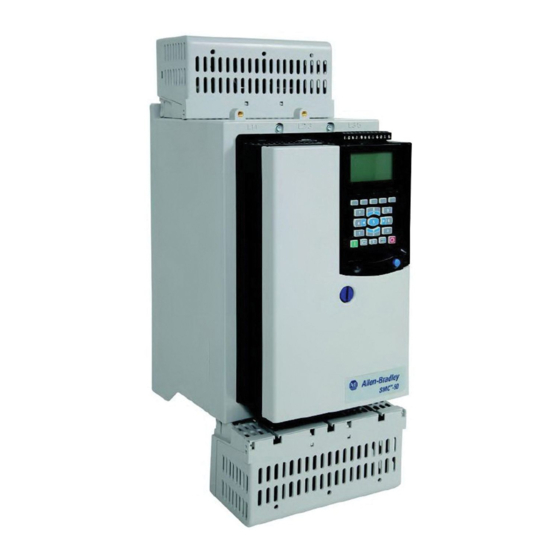
Summary of Contents for Rockwell Automation Allen-Bradley SMC-50
- Page 1 User Manual SMC™-50 Fully Solid-State Smart Motor Controller Bulletin 150...
-
Page 2: Troubleshooting
Braking and Slow Speed) may cause some vibration or noise during the stopping cycle. To minimize vibration or noise, lower the braking current adjustment. If this is a concern in your application, please consult the factory before implementing the braking options. Rockwell Automation Publication 150-UM011A-EN-P - July 2011... - Page 3 Voltage Unbalance or 18 or 42 Running • The delay time programmed is too • Extend the delay time to match the application Current Imbalance short for the application requirements. • Disable this fault/alarm feature. Rockwell Automation Publication 150-UM011A-EN-P - July 2011...
- Page 4 Starts per Hour Starting value increase the programmed start time (if allowed by • Programmed setting is incorrect for the application) and controller thermal limits. the application • Turn off this fault/alarm feature. Rockwell Automation Publication 150-UM011A-EN-P - July 2011...
- Page 5 +MVAR power draw. ➋ Ov Pwr Reac+ Running • Programmed settings are incorrect • Modify the programmed fault/alarm parameters to for the application better suit the application. • Disable the fault/alarm feature. Rockwell Automation Publication 150-UM011A-EN-P - July 2011...
- Page 6 • Wait for motor to cool or provide external cooling, X059 Motor PTC In All Modes then check resistance of PTC. NOTE: An optional 150-SM2 • Disable this fault/alarm feature. Ground Fault PTC Module is required for this fault. Rockwell Automation Publication 150-UM011A-EN-P - July 2011...
- Page 7 • A start event (command) has • NA Start Starting occurred. This is not a fault. • A slow speed event (command) has • NA Slow Speed Slow Speed occurred. This is not a fault. Rockwell Automation Publication 150-UM011A-EN-P - July 2011...
-
Page 8: Troubleshooting Chapter
(e.g., Underload, Overload, Jam, Stall, etc.) does not provide. To understand what is an abnormal running operation, a "normal" or "typical" value, usually established during system startup, needs to be determined by the user. ➌ If controller based motor overload is disabled, external motor overload protection should be used. Rockwell Automation Publication 150-UM011A-EN-P - July 2011... - Page 9 • Check for binding or external loading Inadequate Current Limit and correct setting • Check motor • Failed control module • Adjust the Current Limit Level to a higher setting • Replace control module Rockwell Automation Publication 150-UM011A-EN-P - July 2011...
- Page 10 0.0 Amps if necessary • Failed control module • Replace control module Starting • One or more power phases are • Check power system missing • Failed control module • Replace control module Rockwell Automation Publication 150-UM011A-EN-P - July 2011...
- Page 11 • Ensure power terminals are secure. ➊ Fan operation is controlled by the SMC-50 Control Module. The fan may not run in low ambient temperatire conditions. Refer to Chapter 2, Fan Power on page 28 for additional details. Rockwell Automation Publication 150-UM011A-EN-P - July 2011...
-
Page 12: Power Module Check
(L1-T1, L2-T2, & L3-T3) The resistance should be greater than 5,000 ohms. Replace the power assembly if this reading is not reached. Refer to Appendix C for the list of Spare/Replacement SMC-50 parts. Rockwell Automation Publication 150-UM011A-EN-P - July 2011... - Page 13 Chapter 10 Troubleshooting Rockwell Automation Publication 150-UM011A-EN-P - July 2011...


Need help?
Do you have a question about the Allen-Bradley SMC-50 and is the answer not in the manual?
Questions and answers