
Subscribe to Our Youtube Channel
Related Manuals for Rockwell Automation PowerFlex 753


Summary of Contents for Rockwell Automation PowerFlex 753
- Page 1 Reference Manual Rockwell Automation Library of Process Objects: PowerFlex 753 Drive (P_PF753) Version 3.5...
- Page 2 If this equipment is used in a manner not specified by the manufacturer, the protection provided by the equipment may be impaired. In no event will Rockwell Automation, Inc. be responsible or liable for indirect or consequential damages resulting from the use or application of this equipment.
-
Page 3: Table Of Contents
Alarms Tab ..........60 PowerFlex 753 Drive Faceplate Help ......62... - Page 4 Table of Contents Notes: Rockwell Automation Publication SYSLIB-RM044D-EN-P - February 2017...
-
Page 5: Preface
For the latest compatible software information and to download the Rockwell Automation® Library or Process Objects, see the Product Compatibility and Download Center at http://www.rockwellautomation.com/rockwellautomation/support/pcdc.page. For general library considerations, see Rockwell Automation Library of Process Objects, publication PROCES-RM002. Additional Resources These documents contain additional information concerning related products from Rockwell Automation. - Page 6 Inhibit for Large Motor (P_ResInh) Reference Manual, caused by repeated starts. publication SYSLIB-RM009 Rockwell Automation Library of Process Objects: Run Time Explains how to accumulate the total run time and and Starts (P_RunTime) Reference Manual, count of starts for a motor or other equipment.
-
Page 7: Guidelines
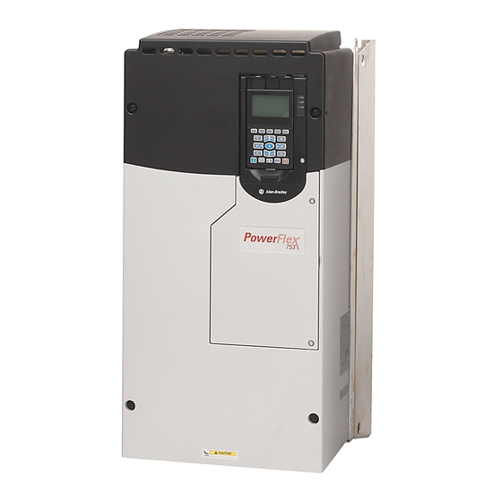
PowerFlex 753 Drive (P_PF753) The P_PF753 (PowerFlex 753 Drive) object is used to operate one variable-speed motor by using a PowerFlex 753 AC variable frequency drive in various modes, and monitoring for fault conditions. The global objects and following faceplate are examples of the graphical interface tools for this Add-On Instruction. -
Page 8: Functional Description
PowerFlex 753 Drive (P_PF753) • If your PowerFlex 753 drive uses the 20-750-ENETR EtherNet interface, use the P_PF755 instruction instead. The PowerFlex 753 drive with the 20-750-ENETR interface uses the same interface data structures as the PowerFlex 755 drive, giving you more data. -
Page 9: Required Files
FactoryTalk View ME Software Description All .png files in the images folder All .png files in the images folder These are the common icons used in the global objects and standard displays for all Process Objects. Rockwell Automation Publication SYSLIB-RM044D-EN-P - February 2017... - Page 10 (RA-BAS-ME) P_Perm-Faceplate Optional Permissive faceplate that is used for the object Use this file if your object has an associated P_Perm object and you enable navigation to the P_Perm faceplate from the object faceplate. Rockwell Automation Publication SYSLIB-RM044D-EN-P - February 2017...
-
Page 11: Controller Code
Table 7 - P_PF753 Drive InOut Parameters Tag Name Data Type Description P_PF753_Inp Common part of PowerFlex 753 input assembly. P_PF753_Out Common part of PowerFlex 753 output assembly. Ref_FaultCodeList P_DescList[*] Array tag containing list of fault codes (DINT) and their descriptions (STRING_40). - Page 12 Each fault code list has preset codes and descriptions that provide human- readable descriptions of drive fault conditions. For a complete list of fault codes for the PowerFlex 753 Drive, refer to the PowerFlex 750 Series AC Drivers Programming Manual, publication 750-PM001.
-
Page 13: Powerflex 753 Drive Input Structure
1 = Stop 2 = Start Fwd 3 = Start Rev Inp_OvrdSpeed REAL Value to set Speed Reference in Override mode (SpeedRef engineering units). Inp_Reset BOOL 1 = Reset drive fault conditions and latched Alarms. Rockwell Automation Publication SYSLIB-RM044D-EN-P - February 2017... - Page 14 Program if no mode is being requested. When this parameter is 0, the mode defaults to Operator if no mode is being requested. IMPORTANT: Changing this parameter online can cause unintended mode changes. Rockwell Automation Publication SYSLIB-RM044D-EN-P - February 2017...
- Page 15 Fail.OCmd_Ack) is required to acknowledge the alarm. When set to 0, the Cfg_IntlkTripAckReqd IntlkTrip.Cfg_AckReqd Acknowledge bit is set when an alarm occurs indicating an acknowledged alarm and no acknowledge command is required. Cfg_DriveFaultAckReqd DriveFault.Cfg_AckReqd Cfg_IOFaultAckReqd IOFault.Cfg_AckReqd Rockwell Automation Publication SYSLIB-RM044D-EN-P - February 2017...
- Page 16 When Cfg_PCmdClear is 0: • Set PCmd_Start to 1 to start the drive • Set PCmd_Start to 0 to stop the drive • PCmd_Stop is not used • These parameters do not reset automatically Rockwell Automation Publication SYSLIB-RM044D-EN-P - February 2017...
- Page 17 • Set PCmd_<Alarm>Suppress to 1 to suppress alarm • Set PCmd_<Alarm>Suppress to 0 to unsuppress alarm PCmd_IOFaultSuppress IOFault.PCmd_Suppress • PCmd_<Alarm>Unsuppress is not used PCmd_FailToStartUnsuppress FailToStart.PCmd_Unsuppress • These parameters do not reset automatically PCmd_FailToStopUnsuppress FailToStop.PCmd_Unsuppress PCmd_IntlkTripUnsuppress IntlkTrip.PCmd_Unsuppress PCmd_DriveFaultUnsuppress DriveFault.PCmd_Unsuppress PCmd_IOFaultUnsuppress IOFault.PCmd_Unsuppress Rockwell Automation Publication SYSLIB-RM044D-EN-P - February 2017...
- Page 18 BOOL Operator command to reset all alarms requiring reset and trigger a drive reset if the drive is faulted. OCmd_ResetAckAll BOOL Operator command to acknowledge and reset all alarms and latched Shed conditions. Rockwell Automation Publication SYSLIB-RM044D-EN-P - February 2017...
-
Page 19: Powerflex 753 Drive Output Structure
Minimum of Speed Reference = MIN (Cfg_SpeedFdbkEUMin, Cfg_SpeedFdbkEUMax). (engineering units) Val_SpeedRefEUMax REAL Maximum of Speed Reference = MAX (Cfg_SpeedFdbkEUMin, Cfg_SpeedFdbkEUMax). (engineering units) Val_SpeedFdbkEUMin REAL Minimum of Speed Feedback = MIN (Cfg_SpeedFdbkEUMin, Cfg_SpeedFdbkEUMax). (engineering units) Rockwell Automation Publication SYSLIB-RM044D-EN-P - February 2017... - Page 20 33 = Disabled Val_Fault SINT Device fault status: 0 = None 16 = Fail to Start 17 = Fail to Stop 18 = Drive Fault 32 = I/O Fault 34 = Configuration Error Rockwell Automation Publication SYSLIB-RM044D-EN-P - February 2017...
- Page 21 Predictive Maintenance status (bit mapped) (Par 469). Sts_StartInhibits DINT Drive Start Inhibit reasons (bit mapped) (Par. 933). Sts_Available BOOL 1 = Drive available for control by automation (Program). Sts_Bypass BOOL 1 = Bypassable Interlocks and Permissives are bypassed. Rockwell Automation Publication SYSLIB-RM044D-EN-P - February 2017...
- Page 22 1 = Drive was stopped by an Interlock Not OK (One-Shot). Sts_DriveFault DriveFault.Inp 1 = Drive Fault (see drive display or manual). Sts_IOFault IOFault.Inp I/O Comm Fault status (0 = OK, 1 = Bad). Rockwell Automation Publication SYSLIB-RM044D-EN-P - February 2017...
- Page 23 1 = At least one alarm or latched Shed condition requires Reset or Acknowledged. Rdy_SpeedRef BOOL 1 = Ready to receive OSet_SpeedRef (enables data entry field). P_PF753 BOOL Unique Parameter Name for auto-discovery. Rockwell Automation Publication SYSLIB-RM044D-EN-P - February 2017...
-
Page 24: Powerflex 753 Drive Local Configuration Tags
PowerFlex 753 Drive (P_PF753) PowerFlex 753 Drive Local Configuration Tags Configuration parameters that are array, string, or structure data types cannot be configured as parameters for Add-On Instructions. Configuration parameters of these types appear as local tags to the Add-On Instruction. Local tags can be configured through the HMI faceplates or in Studio 5000 Logix Designer®... -
Page 25: Alarms
Instructions with Cfg_OperKeep and Cfg_ProgKeep keep some aspects of the IMPORTANT device operation with the operator or program regardless of whether the main mode is Program or Operator mode. See Rockwell Automation Library of Process Objects: Common Mode Block (P_Mode) Reference Manual, publication SYSLIB-RM005, for more information. Alarms This instruction uses the following alarms, which are implemented by using embedded P_Alarm and P_Gate Add-On Instructions. -
Page 26: Simulation
Use this if raw ranges for feedback and reference are different. You can also use Cfg_SimRampT to ramp the speed feedback (in seconds). When you have finished in simulation, set the Inp_Sim parameter in the controller to ‘0’ to return to normal operation. Rockwell Automation Publication SYSLIB-RM044D-EN-P - February 2017... -
Page 27: Execution
1. On the Controller Organizer, add your PowerFlex drive to the I/O Configuration and name the drive. 2. Under Tasks, click the plus sign ( ) in front of Main Task. 3. Double-click Main_Routine to open this ladder logic routine. Rockwell Automation Publication SYSLIB-RM044D-EN-P - February 2017... - Page 28 Final Name column. Your ladder logic routine now looks like the example. Observe that the tag names and your drive's name are automatically placed in the instruction. Rockwell Automation Publication SYSLIB-RM044D-EN-P - February 2017...
- Page 29 • Drive Status 1 (Port 0, Parameter 935) • Drive Status 2 (Port 0, Parameter 936) • Last Fault Code (Port 0, Parameter 951) • Fault Status A (Port 0, Parameter 952) • Fault Status B (Port 0, Parameter 953) Rockwell Automation Publication SYSLIB-RM044D-EN-P - February 2017...
-
Page 30: Display Elements
These display elements show the different motor positions (right, up, and down). GO_P_VSD_U GO_P_VSD_D GO_P_VSD_Blower_R These display elements show the different blower positions (right, left, up, and down). GO_P_VSD_Blower_L GO_P_VSD_Blower_U GO_P_VSD_Blower_D GO_P_VSD_Conveyer_R This display element illustrates a conveyer. Rockwell Automation Publication SYSLIB-RM044D-EN-P - February 2017... - Page 31 These display elements show the different pump positions (left, up, and down). GO_P_VSD_Pump_L GO_P_VSD_Pump_U GO_P_VSD_Agitator_D This display element illustrates an agitator in the down position. GO_P_VSD_Mixer_U This display element shows a mixer in the up position. Rockwell Automation Publication SYSLIB-RM044D-EN-P - February 2017...
- Page 32 • Color changing alarm border that blinks on unacknowledged alarm • Alarm indicator that changes color with the severity of an alarm State Maintenance Bypass Indicator Alarm Border Alarm Indicator Status/Quality Indicator Mode Indicator Status/Quality Indicator Speed Feedback Display Engineering Units Label Rockwell Automation Publication SYSLIB-RM044D-EN-P - February 2017...
-
Page 33: State Indicators
Data Quality degraded: uncertain, test, simulation, substitution, or out of specification. The input or device has been disabled. Device not ready to operate. Speed reference limited to minimum/maximum. Motor is at target speed. Drive is accelerating. Drive is decelerating. Rockwell Automation Publication SYSLIB-RM044D-EN-P - February 2017... - Page 34 When you navigate to the tab, the condition preventing operation is flagged. For the PowerFlex 753 Drive Instruction, the Device Not Ready indicator appears under the following conditions: • Device has been disabled by Maintenance.
-
Page 35: Mode Indicators
This behavior can be changed by replacing the image files for these mode indicators with images that are not transparent. See Rockwell Automation Library of Process Objects: Common Mode Block (P_Mode) Reference Manual, publication SYSLIB-RM005, for more information. -
Page 36: Maintenance Bypass Indicator
Once you navigate to the tab, the bypassed item is flagged with this indicator. For the PowerFlex 753 Drive Instruction, the Maintenance Bypass Indicator appears when the bypassable interlocks and permissives have been bypassed. -
Page 37: Using Display Elements
1. Copy the global object from the global object file and paste it in the display file. 2. In the display, right-click the global object and choose Global Object Parameter Values. The Global Object Parameter Values dialog box appears. Rockwell Automation Publication SYSLIB-RM044D-EN-P - February 2017... - Page 38 3. Type the tag or value in the Value column as specified in the Description column. You can click the ellipsis (…) to browse and select a tag. Values for items marked ‘(optional)’ can be left blank. 4. Click OK. Rockwell Automation Publication SYSLIB-RM044D-EN-P - February 2017...
-
Page 39: Quick Display
When a given input is restricted via FactoryTalk View security, the required user security-code letter is shown in the tables that follow. Rockwell Automation Publication SYSLIB-RM044D-EN-P - February 2017... -
Page 40: Operator Tab
Run Time Navigation Button Navigation Button Speed Reference Reverse Permissive Navigation Button Forward Direction Command Button Drive Ready Indicator Reverse Direction Command Button Input Source and Quality Indicator Input Source and Quality Icon Rockwell Automation Publication SYSLIB-RM044D-EN-P - February 2017... - Page 41 Click to Stop drive. Click to Jog drive. Click to select forward direction. Click to select reverse direction. Click to open Reverse Permissive faceplate. None Click to open Forward Permissive faceplate. Click to open Interlock faceplate. Rockwell Automation Publication SYSLIB-RM044D-EN-P - February 2017...
- Page 42 P_RunTime instruction, the Runtime button is not displayed. See these publications for more information: • Rockwell Automation Library of Process Objects: Interlock with First Out and Bypass (P_Intlk) Reference Manual, publication SYSLIB-RM004 • Rockwell Automation Library of Process Objects: Permissives with Bypass...
- Page 43 All conditions OK, bypass active All conditions OK Alarm indicators appear on the Operator tab when the corresponding alarm occurs. Fail to Start Fail to Stop Alarm Alarm Interlock Trip Alarm Drive Fault Alarm I/O Fault Alarm Rockwell Automation Publication SYSLIB-RM044D-EN-P - February 2017...
-
Page 44: Maintenance Tab
• Requested modes Indicator - This display highlights all modes that have been requested. The leftmost highlighted mode is the active mode. • Whether the motor is enabled or disabled. • Interlock and Permissive Bypassed/Enabled indicator. Rockwell Automation Publication SYSLIB-RM044D-EN-P - February 2017... - Page 45 Table 15 - Maintenance Tab Page 1 Description Function Action Security Configuration Parameters Click for Maintenance mode. Equipment None Maintenance (Code C) Click to release Maintenance mode. Click to enable drive. Click to disable drive. Rockwell Automation Publication SYSLIB-RM044D-EN-P - February 2017...
- Page 46 (Code H) bypassable interlocks and permissives. In Override mode, Check to have the bypassable Cfg_OvrdPermIntlk bypass Interlocks interlocks and permissives bypassed and Permissives in Override mode. that can be bypassed Maintenance Tab Page 2 Rockwell Automation Publication SYSLIB-RM044D-EN-P - February 2017...
- Page 47 Type the clamping limits for the • Cfg_MaxSpdRef Limits (Minimum speed reference. If a speed reference • Cfg_MinSpdRef and Maximum) outside this range is entered, the speed is clamped at these limits and Sts_SpeedLimited is asserted. Rockwell Automation Publication SYSLIB-RM044D-EN-P - February 2017...
-
Page 48: Engineering Tab
Raw Maximum and Minimum Speed Feedback EU Maximum and Minimum Speed Feedback Engineering Units Speed Reference Engineering Units Simulated Speed Speed Reference Loopback Options EU Maximum and Minimum Speed Reference Raw Maximum and Minimum Rockwell Automation Publication SYSLIB-RM044D-EN-P - February 2017... - Page 49 Use this setting if the reference and feedback ranges do not correspond. Rockwell Automation Publication SYSLIB-RM044D-EN-P - February 2017...
- Page 50 Name for forward direction. Cfg_FwdText Reverse Text Name for reverse direction. Cfg_RevText Clear Program Check to have the P_PF753 Cfg_PCmdClear Commands on instruction clear Program commands Receipt (PCmd) as soon as they are received (default). Rockwell Automation Publication SYSLIB-RM044D-EN-P - February 2017...
- Page 51 If no mode is being requested, changing the default mode changes the mode IMPORTANT of the instruction. You must have FactoryTalk View security code E to select the default mode on this display. Rockwell Automation Publication SYSLIB-RM044D-EN-P - February 2017...
- Page 52 Forward Permissive object in the controller must be this object's name with the suffix ‘_FwdPerm’ . For example, if your P_PF753 object has the name ’Drive123’ , then its Forward Permissive object must be named ‘Drive123_FwdPerm’ . Rockwell Automation Publication SYSLIB-RM044D-EN-P - February 2017...
- Page 53 ‘_RunTime’ . For example, if your P_PF753 object has the name ‘Drive123’ , then its runtime object must be named ‘Drive123_RunTime’ . Rockwell Automation Publication SYSLIB-RM044D-EN-P - February 2017...
- Page 54 Stop Drive on The drive always stops on an None None Interlock Trip Interlock trip. This item cannot be cleared. It is displayed as a reminder that the Interlock Trip function always stops the drive. Rockwell Automation Publication SYSLIB-RM044D-EN-P - February 2017...
- Page 55 Program keeps Speed Reference with the Program, control in Operator even if the instruction is in Operator mode mode. Clear this checkbox to have control of the drive Speed Reference follow the Instruction mode. Rockwell Automation Publication SYSLIB-RM044D-EN-P - February 2017...
- Page 56 HMI or program only. Time to ramp speed Enter the time, in seconds, to ramp Cfg_SimRampT feedback when in speed feedback when in Loopback Loopback Test Test. (seconds) Rockwell Automation Publication SYSLIB-RM044D-EN-P - February 2017...
-
Page 57: Diagnostics Tabs
'Not Ready' , device warnings and faults, warning and fault history, and predictive/preventive maintenance data. This tab is divided into six pages. Each page provides you with diagnostic feedback on the drive. Rockwell Automation Publication SYSLIB-RM044D-EN-P - February 2017... -
Page 58: Diagnostic Tab (Continued)
PowerFlex 753 Drive (P_PF753) Diagnostic Tab (continued) Rockwell Automation Publication SYSLIB-RM044D-EN-P - February 2017... -
Page 59: Trends Tab
The Trends tab shows trend charts of key device data over time. These faceplate trends provide a quick view of current device performance to supplement, but not replace, dedicated historical or live trend displays. Speed Reference Speed Feedback Rockwell Automation Publication SYSLIB-RM044D-EN-P - February 2017... -
Page 60: Alarms Tab
The color of the bell icon at the top of the faceplate shows the severity of the highest active alarm, and the icon blinks if any alarm is unacknowledged or requires reset. Rockwell Automation Publication SYSLIB-RM044D-EN-P - February 2017... - Page 61 The Alarm Acknowledge button is enabled if the alarm requires acknowledgment. Click the button with the check mark to acknowledge the alarm. See Rockwell Automation Library of Process Objects: Common Alarm Block (P_Alarm) Reference Manual, publication SYSLIB-RM002, for more information.
-
Page 62: Powerflex 753 Drive Faceplate Help
PowerFlex 753 Drive (P_PF753) PowerFlex 753 Drive Faceplate Help The Faceplate Help is divided into two pages. Faceplate Help Page 1 Faceplate Help Page 2 Rockwell Automation Publication SYSLIB-RM044D-EN-P - February 2017... - Page 64 New Product Satisfaction Return Rockwell Automation tests all of its products to help ensure that they are fully operational when shipped from the manufacturing facility. However, if your product is not functioning and needs to be returned, follow these procedures.
Need help?
Do you have a question about the PowerFlex 753 and is the answer not in the manual?
Questions and answers
TRYING TO FIND THE PARAMETERS FOR SETTING THE REFERENCE INPUT MIN / MAX AND THE OUTPUT FREQUENCY, MIN / MAX TO THE MOTOR
The parameters for setting the reference input minimum/maximum and the output frequency minimum/maximum for the Rockwell Automation PowerFlex 753 are:
- Cfg_SpeedRefRawMin: Sets the raw minimum reference input.
- Cfg_SpeedRefRawMax: Sets the raw maximum reference input.
- Cfg_SpeedFdbkEUMin: Sets the engineering units minimum for speed feedback.
- Cfg_SpeedFdbkEUMax: Sets the engineering units maximum for speed feedback.
These parameters define the scaling range for both input reference and output feedback.
This answer is automatically generated