Rockwell Automation Allen-Bradley AADvance T9110 Troubleshooting And Maintenance Manual
Hide thumbs
Also See for Allen-Bradley AADvance T9110:
- Solutions handbook (165 pages) ,
- System build manual (150 pages)

Related Manuals for Rockwell Automation Allen-Bradley AADvance T9110


Summary of Contents for Rockwell Automation Allen-Bradley AADvance T9110
- Page 1 AADvance Controller Catalog Numbers T9110, T9300, T9310, T9401/2, T9431/2, T9451, T9481/2 Original Instructions Troubleshooting and Maintenance Manual...
- Page 2 If this equipment is used in a manner not specified by the manufacturer, the protection provided by the equipment may be impaired. In no event will Rockwell Automation, Inc. be responsible or liable for indirect or consequential damages resulting from the use or application of this equipment.
-
Page 3: Preface
This technical manual describes how to maintain, troubleshoot, and repair an AADvance® controller. In no event will Rockwell Automation be responsible or liable for indirect or consequential damages resulting from the use or application of this equipment. The examples given in this manual are included solely for illustrative purposes. - Page 4 For the latest information about this product review the Product Notifications and Technical Notes issued by technical support. Product Notifications and product support are available at the Rockwell Automation Support Center at rok.auto/knowledgebase. At the Search Knowledgebase tab select the option "By Product" then scroll down and select the ICS Triplex®...
-
Page 5: Download Firmware, Aop, Eds, And Other Files
Digital Output tagname name Changed Added steps for AADvance Workbench software Examine the State Variable version 2.x and AADvance-Trusted SIS Workstation software. Added AADvance-Trusted SIS Workstation Software software AADvance license. Glossary Updated several entries. Rockwell Automation Publication ICSTT-RM406J-EN-P - February 2021... -
Page 6: Additional Resources
ICSTT-RM406 Controller. Industrial Automation Wiring and Grounding Guidelines, publication 1770-4.1 Provides general guidelines for installing a Rockwell Automation industrial system. Product Certifications website, rok.auto/certifications. Provides declarations of conformity, certificates, and other certification details. Rockwell Automation Publication ICSTT-RM406J-EN-P - February 2021... -
Page 7: Table Of Contents
Fault Indications..........36 I/O Module Channel Degradation and Shutdown ....38 Rockwell Automation Publication ICSTT-RM406J-EN-P - February 2021... - Page 8 Termination Assemblies ......... 77 Rockwell Automation Publication ICSTT-RM406J-EN-P - February 2021...
- Page 9 Glossary ........... . . 83 Rockwell Automation Publication ICSTT-RM406J-EN-P - February 2021...
- Page 10 Rockwell Automation Publication ICSTT-RM406J-EN-P - February 2021...
-
Page 11: Making Repairs Promptly
• Screwdriver, cross head number 0, for battery cover on 9110 processor module • Screwdriver, flat 0.8 mm x 4.0 mm (1/25 inch x 5/32 inch), for screws on extension cables Rockwell Automation Publication ICSTT-RM406J-EN-P - February 2021... -
Page 12: Required Test Equipment
• Output range 4 mA to 20 mA with an accuracy better than 0.05 mA. 3. Bench power supply • Output range 0 V to 32 Vdc. Return a Module Before returning a module, contact your local Rockwell Automation technical support representative or send an email to returns@ra.rockwell.com to get a Return Material Authorization (RMA) number. - Page 13 Chapter 1 Introduction to Maintenance Activities Figure 1 - Flowchart Conventions Rockwell Automation Publication ICSTT-RM406J-EN-P - February 2021...
- Page 14 Chapter 1 Introduction to Maintenance Activities Notes: Rockwell Automation Publication ICSTT-RM406J-EN-P - February 2021...
-
Page 15: Preventive Maintenance Schedule
Measure digital output module calibration values 3 years Do a manual test Manual Test Interval NOTE All modules are returned to Rockwell Automation® for calibration. To return a module see Return a Module on page IMPORTANT Testing of the logic solver and its related field devices must be carried out according to the applicable plant or process safety analysis and the safety integrity validation. -
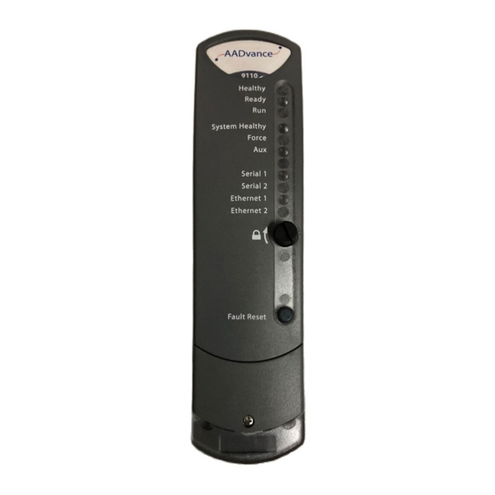
Page 16: Status Indicators On The 9110 Processor Module
• Module is in the shutdown state. Ready Flashing The module is being educated or synchronized. GREEN GREEN Module is educated and synchronized with partners. AMBER Module is in Recovery Mode. Rockwell Automation Publication ICSTT-RM406J-EN-P - February 2021... - Page 17 Quickly alternating Tx and Rx activity. No power and stays off while the module is booting up (10 to 20 seconds) Ethernet 1 and 2 GREEN Ethernet link present AMBER Tx or Rx activity on Ethernet Port Rockwell Automation Publication ICSTT-RM406J-EN-P - February 2021...
-
Page 18: Status Indicators On The 94Xx Series Input And Output Module
Module is inserted into a running system but not on-line. Push the Fault AMBER Reset button on any processor module to set the module to go on-line. Module is prepared to go on-line but no application is running. Rockwell Automation Publication ICSTT-RM406J-EN-P - February 2021... -
Page 19: Check Fuses
Output module: output is in its energized condition. AMBER Field fault. Channel fault. Check Fuses 1. Open the fuse cover on each termination assembly and examine the fuses. 2. Look for signs of overheated, damaged, or incorrectly seated fuses. Rockwell Automation Publication ICSTT-RM406J-EN-P - February 2021... -
Page 20: Check Wiring Terminals
3.95 mA to 4.05 mA. 4. Set the current simulation instrument to supply 12 mA, make sure that the input value is in the range 11.95 mA to 12.05 mA. Rockwell Automation Publication ICSTT-RM406J-EN-P - February 2021... -
Page 21: Check Digital Input Module Calibration Values
At the same time, make sure that each output operates as expected. Use the application software to force the outputs which do not seem to operate. • Carry out a manual examination to test each input and output. Rockwell Automation Publication ICSTT-RM406J-EN-P - February 2021... - Page 22 Chapter 2 Preventive Maintenance Notes: Rockwell Automation Publication ICSTT-RM406J-EN-P - February 2021...
-
Page 23: View Module Firmware Versions
Chapter Upgrading Controller Firmware Rockwell Automation issues firmware upgrades for processor modules from time to time. This chapter provides an overview of the firmware upgrade process and the instructions for using the ControlFLASH™ software. WARNING: Do not attempt to upgrade firmware on a running system. - Page 24 • Slot - the slot the module has been allocated • Module - the module identity • Serial - the module hardware serial number • Versions - The firmware versions in the module 5. Click Apply Rockwell Automation Publication ICSTT-RM406J-EN-P - February 2021...
-
Page 25: Upgrade The Processor Module Firmware
Firmware update tool used for electronically updating firmware. • T9110 Processor Module firmware files • Firmware for T9110 Processor Module v1.040 (T9110_1.040.dmk) • Firmware for T9110 Recovery Mode Processor Module version 1.001 (T9110_Recovery_Mode_1.001.103.dmk) Rockwell Automation Publication ICSTT-RM406J-EN-P - February 2021... -
Page 26: Install Software
5. Perform the step that corresponds to the selected driver type: • Ethernet devices Select OK, then for each device, enter the IP address (or Host Name if DNS is supported) under Host Name. Select Add New as necessary. Rockwell Automation Publication ICSTT-RM406J-EN-P - February 2021... -
Page 27: Use Controlflash To Upgrade Firmware
7. Close the RSLinx Classic Lite software. Use ControlFLASH to upgrade firmware Use ControlFLASH to simultaneously upgrade the firmware of up to three processor modules that are installed in the same processor base unit. Rockwell Automation Publication ICSTT-RM406J-EN-P - February 2021... - Page 28 Aux status indicator becomes amber. The Aux status indicator becomes amber to indicate that the module is loading Recovery Mode. When the module is ready, the Ready, Run, Force, and Aux status indicators become amber. Rockwell Automation Publication ICSTT-RM406J-EN-P - February 2021...
- Page 29 Status dialog box prompts that the update is completed. The processor module operational firmware is updated. 11. View the module firmware version to verify that the upgrade is successful. For more information, see View Module Firmware Versions on page Rockwell Automation Publication ICSTT-RM406J-EN-P - February 2021...
- Page 30 Chapter 3 Upgrading Controller Firmware Notes: Rockwell Automation Publication ICSTT-RM406J-EN-P - February 2021...
-
Page 31: Prerequisites For Troubleshooting
There is also a summary system healthy indication for all of the controller. The application uses its variable structures to report a fault problem; these variables give status reports and are configured using the Rockwell Automation Publication ICSTT-RM406J-EN-P - February 2021... -
Page 32: Actions Of The Diagnostic Systems
As an example, a non-critical item might be monitored every three hours and reported after 24 hours like this. Figure 2 - Diagnostic Threshold Pushing the Fault Reset button resets every counter which has reached the fault threshold. Rockwell Automation Publication ICSTT-RM406J-EN-P - February 2021... -
Page 33: Latching And Non-Latching Faults
• Extract diagnostic data. (a) For AADvance Workbench software version 1.x. (b) For AADvance Workbench software version 2.1 and AADvance-Trusted SIS Workstation software. AADvance Workbench software version 2.0 does not support this feature. Rockwell Automation Publication ICSTT-RM406J-EN-P - February 2021... - Page 34 Reset button pushed the module enters Recovery Mode. Recovery Mode with Fault Present After a critical application failure the Healthy and System Healthy status indicators stay Green for a number of seconds then go Red. Rockwell Automation Publication ICSTT-RM406J-EN-P - February 2021...
- Page 35 • Check: the application program to see if the I/O module is installed in the equipment and if so if it is installed into the correct I/O Bus and Slot. Rockwell Automation Publication ICSTT-RM406J-EN-P - February 2021...
-
Page 36: Fault Indications
A channel fault produces a module fault indication and a system fault indication, similarly a module fault will also produce a system fault. The relationships between the classes of faults and the status indicators are shown in the illustration. Rockwell Automation Publication ICSTT-RM406J-EN-P - February 2021... - Page 37 Channel Fault The controller indicates a channel fault when it detects a fault and can isolate it to a fault on a channel of an I/O module. The controller always reports a Rockwell Automation Publication ICSTT-RM406J-EN-P - February 2021...
-
Page 38: I/O Module Channel Degradation And Shutdown
Discrepancy as TRUE and the module reports 'safe' values back to the application for the faulty channel. Degraded Channel Reporting Values When a fault exists on a channel, the module will report safe values for that channel and the Discrepancy status variable reports TRUE. Rockwell Automation Publication ICSTT-RM406J-EN-P - February 2021... -
Page 39: Output Channel Shutdown
As long as one module in a group continues to receive updated command state values from a running application in the PST, each channel is driven according to its commanded state. This covers the situation when only one module out of Rockwell Automation Publication ICSTT-RM406J-EN-P - February 2021... - Page 40 This makes sure that these channels do not get stuck energized, and that the remaining module can energize or de-energize these channels according to the commanded state received from a running application. Rockwell Automation Publication ICSTT-RM406J-EN-P - February 2021...
-
Page 41: Troubleshooting Module Faults
Failure to follow these instructions can cause injury. Troubleshooting Module Use this flow chart to start a new fault investigation. Faults Figure 4 - Fault Finding Process - System Level Rockwell Automation Publication ICSTT-RM406J-EN-P - February 2021... -
Page 42: Rectify A Critical Processor Firmware/Hardware Failure
If you are installing more than one processor module make sure they all have the same firmware build. Installation 1. Examine the coding pegs on the 9100 processor base unit and make sure they fit the sockets on the rear of the processor module: Rockwell Automation Publication ICSTT-RM406J-EN-P - February 2021... -
Page 43: Processor Module Start Up Process
With the power switched on place the processor module into slot A on the Base Unit connectors and push the module home until the connectors are fully mated. Turn the locking screw and lock the module in position. Rockwell Automation Publication ICSTT-RM406J-EN-P - February 2021... - Page 44 If the firmware revision is different upgrade the firmware using the ControlFLASH™. IMPORTANT When inserting a second and third processor module they MUST be inserted one at a time and allowed to educate before inserting the next one. Rockwell Automation Publication ICSTT-RM406J-EN-P - February 2021...
-
Page 45: Faulty Processor Back-Up Battery
The battery condition is monitored by the module diagnostics every 24 hours. If the battery voltage is low or the battery is missing, a variable and the Battery processor module Healthy status indicator goes red indicating a faulty battery, which needs replacing. Rockwell Automation Publication ICSTT-RM406J-EN-P - February 2021... -
Page 46: Replace A Faulty Processor Back-Up Battery
NOTE For a new processor the backup battery is supplied separately and must be installed into each new processor module. Replace a Faulty Processor Back-up Battery Use the following official Rockwell Automation battery or one of an equivalent specification. Part No and Description T9905: Polycarbon monofluoride Lithium Coin Battery, BR2032 (recommended type), 20 mm dia;... - Page 47 Procedure To replace a faulty battery, do the following: 1. Use a small cross head screwdriver to release and remove the battery cover. 2. Remove the battery by pulling on the blue ribbon. Rockwell Automation Publication ICSTT-RM406J-EN-P - February 2021...
- Page 48 Processor diagnostic log entries. The specific functions that the battery maintains on complete loss of power are the following: • Real Time Clock – The battery provides power to the RTC chip itself. Rockwell Automation Publication ICSTT-RM406J-EN-P - February 2021...
-
Page 49: Remote Fault Reset/Join
The following procedure assists in setting the clock: Set up the following variables in the Dictionary RTC Control Variables (all BOOLEAN Outputs) • RTC Control: RTC_Read • RTC Control: RTC_Write • RTC Control: Year Rockwell Automation Publication ICSTT-RM406J-EN-P - February 2021... - Page 50 4. Lock and force the RTC Read variable to TRUE. 5. The RTC Status now displays the new date and time of the processor. 6. Unlock all the RTC Control variables. Rockwell Automation Publication ICSTT-RM406J-EN-P - February 2021...
-
Page 51: Understanding The State Variable (
A digital input channel without line monitoring can find and report states 2, 3, 4, 6 and 7, but cannot find an open circuit or short circuit. A line monitored input can find and report every state, including an open circuit or short circuit. Rockwell Automation Publication ICSTT-RM406J-EN-P - February 2021....Sta) -
Page 52: Correlation Of Status Indicators With State Variable For An Analogue
Troubleshooting and Rectifying Channel/Field Faults Correlation of Status Indicators with State Variable for an Analogue Input Analogue input channels are always line monitored. An analogue input channel can detect and report every state from 1 to 7. Rockwell Automation Publication ICSTT-RM406J-EN-P - February 2021... - Page 53 Chapter 6 Troubleshooting and Rectifying Channel/Field Faults Analogue Inputs Digital Input Healthy Channel State Condition .STA Faulted Channel fault Over voltage Amber Short circuit Energised Green Field fault Green Indeterminate De-energised Amber Open circuit Rockwell Automation Publication ICSTT-RM406J-EN-P - February 2021...
-
Page 54: Correlation Of Status Indicators With State Variable For A Digital
For details on how the AADvance digital output module detects field faults, see Knowledgebase Document ID: QA23147 AADvance/bulletin 1715: Digital output channel diagnostic test. Sign in to your Rockwell Automation account to view Knowledgebase articles. Rockwell Automation Publication ICSTT-RM406J-EN-P - February 2021... -
Page 55: Correlation Of Status Indicators With State Variable For An Analogue
• For analogue input modules use chart 'B'. • For digital output modules use chart 'C'. • For analogue output modules use chart 'D'. Use this circuit diagram in conjunction with chart 'A'. Rockwell Automation Publication ICSTT-RM406J-EN-P - February 2021... - Page 56 Chapter 6 Troubleshooting and Rectifying Channel/Field Faults Figure 5 - Digital Input Circuit Rockwell Automation Publication ICSTT-RM406J-EN-P - February 2021...
- Page 57 Chapter 6 Troubleshooting and Rectifying Channel/Field Faults Figure 6 - Chart A: Fault finding Process Digital Input Use this circuit diagram in conjunction with chart 'B'. Rockwell Automation Publication ICSTT-RM406J-EN-P - February 2021...
- Page 58 Chapter 6 Troubleshooting and Rectifying Channel/Field Faults Figure 7 - Analogue Input Circuit Rockwell Automation Publication ICSTT-RM406J-EN-P - February 2021...
- Page 59 Chapter 6 Troubleshooting and Rectifying Channel/Field Faults Figure 8 - Chart B: Fault Finding Process Analogue Input Use this circuit diagram in conjunction with chart 'C' Rockwell Automation Publication ICSTT-RM406J-EN-P - February 2021...
- Page 60 Chapter 6 Troubleshooting and Rectifying Channel/Field Faults Figure 9 - Digital Output Circuit Rockwell Automation Publication ICSTT-RM406J-EN-P - February 2021...
- Page 61 Chapter 6 Troubleshooting and Rectifying Channel/Field Faults Figure 10 - Chart C: Fault finding Process Digital Output Use this circuit diagram in conjunction with chart 'D'. Rockwell Automation Publication ICSTT-RM406J-EN-P - February 2021...
- Page 62 Chapter 6 Troubleshooting and Rectifying Channel/Field Faults Figure 11 - Analogue output Circuit Rockwell Automation Publication ICSTT-RM406J-EN-P - February 2021...
-
Page 63: Examine The State Variable
Examine the State Variable Use the State variable (<variablename>.STA) to find field faults. To do this, you have to identify the Name of the variable, and then add the variable to the Spy List: Rockwell Automation Publication ICSTT-RM406J-EN-P - February 2021... - Page 64 3. Select Debug Target and then open the Spy List. 4. Double-click on the Name field. 5. Select the Name for the state variable from the drop down list. • The State variable is added to the Spy list. Rockwell Automation Publication ICSTT-RM406J-EN-P - February 2021...
-
Page 65: Replacing Channel Fuses
If the circuit is energized it is possible to make an electrical arc and cause an explosion. Failure to follow these instructions can cause injury to persons. Replace an Input Channel Fuse 1. Open the fuse cover. Rockwell Automation Publication ICSTT-RM406J-EN-P - February 2021... - Page 66 Chapter 6 Troubleshooting and Rectifying Channel/Field Faults 2. Find the blown fuse and remove it. 3. Insert the new fuse. Rockwell Automation Publication ICSTT-RM406J-EN-P - February 2021...
-
Page 67: Replacing Digital Output Fuses
Replacing Digital Output Fuses To replace a fuse in a Digital Output Termination Assembly do the following: 1. Use a small screwdriver to open the fuse cover. 2. Remove the blown fuse with long nosed pliers. Rockwell Automation Publication ICSTT-RM406J-EN-P - February 2021... -
Page 68: Install I/O Modules
The identification labels on the sides of the I/O module will be hidden when the module is installed. Therefore before installation write down the location of the module and the details shown on the label. Rockwell Automation Publication ICSTT-RM406J-EN-P - February 2021... -
Page 69: I/O Module Start-Up Process
Install the Input/Output Module and turn the locking screw to the lock position. The module will provide the following status indications: Healthy GREEN Ready Channel 1 – 8 The input module will follow its start-up sequence and the module will educate. Rockwell Automation Publication ICSTT-RM406J-EN-P - February 2021... -
Page 70: Install A New Termination Assembly
2. Depress the retaining tab below the termination assembly (multiple tabs for dual and triple modular redundant versions) and then pull the termination assembly downwards. 3. Lift out the termination assembly. Rockwell Automation Publication ICSTT-RM406J-EN-P - February 2021... - Page 71 1. Insert the retaining clip on the back of the termination assembly into the slot on the I/O base unit. • Press the termination assembly onto the base unit and then slide the assembly up as far as it will go. Rockwell Automation Publication ICSTT-RM406J-EN-P - February 2021...
-
Page 72: Operation And Maintenance Plan
Proof Test Interval used to calculate the PFD values. Field Device Maintenance The Operation and Maintenance Plan must include field maintenance activities, such as re-calibration, testing and replacement of field devices. Rockwell Automation Publication ICSTT-RM406J-EN-P - February 2021... -
Page 73: Handling Module Faults
Procedures for tracking all reported anomalies, their temporary solutions and resultant corrective action where applicable • The information requirements placed on the end users by this procedure must be clearly documented and given to the end user Rockwell Automation Publication ICSTT-RM406J-EN-P - February 2021... -
Page 74: Preserving Functional Safety
Decommissioning The procedure for decommissioning the system must be specified. This procedure must include the requirements for the safe decommissioning of the system and, where applicable, the safe removal or return of materials. Rockwell Automation Publication ICSTT-RM406J-EN-P - February 2021... - Page 75 This must include the interaction between systems. • A definition of the modules and materials which are to be returned to Rockwell Automation for ethical disposal following decommissioning. Rockwell Automation Publication ICSTT-RM406J-EN-P - February 2021...
- Page 76 Chapter 6 Troubleshooting and Rectifying Channel/Field Faults Notes: Rockwell Automation Publication ICSTT-RM406J-EN-P - February 2021...
-
Page 77: Base Units
Digital input TA, 16 channel, dual T9803 Digital input TA, 16 channel, TMR T9831 Analogue input TA, 16 channel, simplex, commoned T9832 Analogue input TA, 16 channel, dual T9833 Analogue input TA, 16 channel, TMR Rockwell Automation Publication ICSTT-RM406J-EN-P - February 2021... -
Page 78: Expansion Cable Assembly
IEC 61131 Workbench, USB key, single user, single controller T9082D IEC 61131 Workbench, hard disk key, single user, single controller T9083U IEC 61131 Workbench, USB key, multiple controllers T9083D IEC 61131 Workbench, hard disk key, multiple controllers Rockwell Automation Publication ICSTT-RM406J-EN-P - February 2021... -
Page 79: Demonstration Unit
IEC 61131 AADvance Workbench 2.x T9090 AADvance®-Trusted® SIS Workstation software AADvance® license T9030 OPC portal server Demonstration Unit Part No. Part Description T9141 AADvance Demonstration Unit (Including HMI) Miscellaneous Items Part No. Part Description Rockwell Automation Publication ICSTT-RM406J-EN-P - February 2021... - Page 80 Chapter 7 Parts List Notes: Rockwell Automation Publication ICSTT-RM406J-EN-P - February 2021...
-
Page 81: History Of Changes
Software: Added AADvance-Trusted SIS Workstation software AADvance® license. Glossary: Updated several entries. ICSTT-RM406I-EN-P, July 2019 Change Updated for Release 1.34 IEC 61508 Edition 2.0 certification Updated Preface release number to 1.34 Legal requirements Updated trademarks Removed print location Rockwell Automation Publication ICSTT-RM406J-EN-P - February 2021... - Page 82 Issue 04, November 2010 Change Add fuse replacement Issue 03, April 2009 Change Change title and add calibration procedures Issue 02, February 2009 Change Update with official product titles Issue 01, December 2008 Change First issue Rockwell Automation Publication ICSTT-RM406J-EN-P - February 2021...
-
Page 83: Glossary
An example is ASCII over RS-232-C. See also 'RS-232-C, RS- 422, RS-485'. The probability that a system will be able to carry out its designated function availability when required for use — normally expressed as a percentage. Rockwell Automation Publication ICSTT-RM406J-EN-P - February 2021... - Page 84 A group of conductors which carry related data. Typically allocated to address, data and control functions in a microprocessor-based system. A mechanism for deciding which device has control of a bus. bus arbitration Rockwell Automation Publication ICSTT-RM406J-EN-P - February 2021...
- Page 85 Common Industrial Protocol. A communications protocol, formally known as 'CIP over Ethernet/IP', created by Rockwell Automation for the Logix controller family, and which is also supported by the AADvance controller. AADvance controllers use the protocol to exchange data with Logix controllers.
- Page 86 Item of equipment connected to the field side of the I/O terminals. Such field device equipment includes field wiring, sensors, final control elements and those operator interface devices hard-wired to I/O terminals. Rockwell Automation Publication ICSTT-RM406J-EN-P - February 2021...
- Page 87 A backplane assembly which holds up to three I/O modules and their I/O base unit associated termination assembly or assemblies in an AADvance controller. Part number 9300. See 'I/O module' and 'termination assembly'. Rockwell Automation Publication ICSTT-RM406J-EN-P - February 2021...
- Page 88 The removal and then reinsertion of an electronic module into a system while live insertion the system remains powered. The assumption is that removal of the module and reinsertion will cause no electrical harm to the system. Also referred to as 'hot swap'. Rockwell Automation Publication ICSTT-RM406J-EN-P - February 2021...
- Page 89 The state of a controller that is executing the application. on-line A series of standards specifications which support open connectivity in industrial automation. A value passed from the processor module to an I/O module. output (variable) Rockwell Automation Publication ICSTT-RM406J-EN-P - February 2021...
- Page 90 A set of rules that is used by devices (such as AADvance controllers, serial protocol devices and engineering computers) to communicate with each other. The rules encompass electrical parameters, data representation, signalling, authentication, and error detection. Examples include MODBUS, TCP and IP. Rockwell Automation Publication ICSTT-RM406J-EN-P - February 2021...
- Page 91 Safety Instrumented Function. A form of process control that performs specified functions to achieve or maintain a safe state of a process when unacceptable or dangerous process conditions are detected. Rockwell Automation Publication ICSTT-RM406J-EN-P - February 2021...
- Page 92 Independent third party certification against a defined range of international TÜV certification standards including IEC 61508. Rockwell Automation Publication ICSTT-RM406J-EN-P - February 2021...
- Page 93 A redundant system (m out of n) which requires at least m of the n channels to voting system be in agreement before the system can take action. The maximum voltage level that can be applied between circuits or withstand voltage components without causing a breakdown. Rockwell Automation Publication ICSTT-RM406J-EN-P - February 2021...
- Page 94 Notes: Rockwell Automation Publication ICSTT-RM406J-EN-P - February 2021...
- Page 95 AADvance Controller Troubleshooting and Maintenance Manual Rockwell Automation Publication ICSTT-RM406J-EN-P - February 2021...
- Page 96 At the end of life, this equipment should be collected separately from any unsorted municipal waste. Rockwell Automation maintains current product environmental information on its website at rok.auto/pec. AADvance, Allen-Bradley, ControlFLASH, expanding human possibility, ICS Triplex, Rockwell Automation, Rockwell Software, TechConnect, and Trusted are trademarks of Rockwell Automation, Inc.
Need help?
Do you have a question about the Allen-Bradley AADvance T9110 and is the answer not in the manual?
Questions and answers