
Subscribe to Our Youtube Channel
Related Manuals for Rockwell Automation CompactLogix series


Summary of Contents for Rockwell Automation CompactLogix series
-
Page 1: Table Of Contents
Installation Instructions CompactLogix Controllers Catalog Numbers 1768-L43, 1768-L43S, 1768-L45, 1768-L45S Topic Page Important User Information About CompactLogix Controllers Verify Compatibility Required System Components Clearance Requirements Module Placement Install the Controller Panel Mount the Controller Mount the Controller on a DIN Rail Confirm the Installation Connect to the Controller Configure a Communication Driver... -
Page 2: Important User Information
In no event will Rockwell Automation, Inc. be responsible or liable for indirect or consequential damages resulting from the use or application of this equipment. - Page 3 CompactLogix Controllers 3 Environment and Enclosure This equipment is intended for use in a Pollution Degree 2 industrial environment, ATTENTION in overvoltage Category II applications (as defined in IEC publication 60664-1), at altitudes up to 2000 m (6562 ft) without derating. This equipment is considered Group 1, Class A industrial equipment according to IEC/CISPR Publication 11.
- Page 4 4 CompactLogix Controllers European Hazardous Location Approval Consider the following if you install a 1768-L43S or 1768-L45S controller in a European Zone 2 location. European Zone 2 Certification (The following applies when the product bears the EX marking.) This equipment is intended for use in potentially explosive atmospheres as defined by European Union Directive 94/9/EC and has been found to comply with the Essential Health and Safety Requirements relating to the design and construction of Category 3 equipment intended for use in Zone 2 potentially explosive atmospheres, given in Annex II to this...
- Page 5 CompactLogix Controllers 5 North American Hazardous Location Approval The following information applies when Informations sur l’utilisation de cet operating this equipment in hazardous équipement en environnements dangereux. locations. Products marked "CL I, DIV 2, GP A, B, C, D" are suitable for Les produits marqués "CL I, DIV 2, GP A, B, C, D"...
-
Page 6: About Compactlogix Controllers
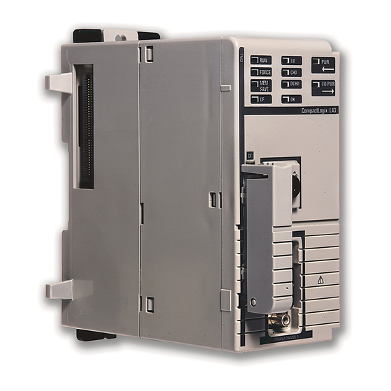
6 CompactLogix Controllers About CompactLogix Controllers CompactLogix 1768-L43 and 1768-L45 controllers are designed to provide a Logix solution for medium-sized applications. Compact GuardLogix controller catalog numbers end in ‘S’. These safety controllers are wider than their standard counterparts. 1768-L43, 1768-L45 1768-L43S, 1768-L45S Verify Compatibility Attempting to use controllers with incompatible software and firmware... -
Page 7: Required System Components
CompactLogix Controllers 7 Required System Components You need these parts when installing your controller: • 1768-L43, 1768-L43S, 1768-L45, or 1768-L45S CompactLogix controller • 1768-PA3 or 1768-PB3 power supply • 1769-ECR end cap • Mounting screws (M4 or #8 panhead) or one of these EN 50 022 DIN rails: –... -
Page 8: Module Placement
8 CompactLogix Controllers Module Placement 1768 Backplane (local) 1768 Controller, Power Remote Bank Supply, and I/O Modules 1769 Power Supply and I/O Modules 1769 Backplane CompactLogix System Distance Ratings IMPORTANT Because the 1768 CompactLogix power supply works with the controller to power a 1768 system, the distance rating in a 1768 CompactLogix system differs from that in a 1769 CompactLogix system. -
Page 9: Install The Controller
CompactLogix Controllers 9 • Up to eight 1769 Compact I/O modules can reside on each side of a 1769 power supply in a remote bank. Consult the module’s specifications for its distance rating. Never place a 1769 power supply in a local bank with a 1768 IMPORTANT controller or a major fault will occur. -
Page 10: Panel Mount The Controller
10 CompactLogix Controllers Panel Mount the Controller Follow these steps to mount your controller by using the panhead screws. 1. Connect the CompactLogix modules together as shown in Mount the Controller on a DIN Rail on page 2. Use the controller as a template and mark pilot holes on your panel. - Page 11 CompactLogix Controllers 11 Mount 1768 Components Follow these steps to mount the controller. 1. Mount the controller on the DIN rail. 31595-M 31596 -M 2. Mount additional 1768 modules to the left of the controller. 31597-M 31598 -M 3. Mount the 1768 power supply and other 1768 modules. 31599-M Publication 1768-IN004D-EN-P - December 2009...
- Page 12 12 CompactLogix Controllers Mount 1769 I/O Modules Follow these steps to mount 1769 I/O modules to the right of the controller. 1. Align the upper and lower tongue-and-groove slots and slide the module back toward the DIN rail until the bus levers line 2.
-
Page 13: Confirm The Installation
CompactLogix Controllers 13 4. Attach the end cap by using the tongue and groove slots (a) and locking the bus lever (b). Confirm the Installation After you have installed the controller and applied power, check that the PWR and I/O PWR status indicators are solid green. Power L2/N If the indicators are in any other state, see... -
Page 14: Connect To The Controller
14 CompactLogix Controllers Connect to the Controller If you connect or disconnect the serial cable with power applied to this module WARNING or the serial device on the other end of the cable, an electrical arc can occur. This could cause an explosion in hazardous location installations. Be sure that power is removed or the area is nonhazardous before proceeding. - Page 15 CompactLogix Controllers 15 Configure a Serial Driver Use RSLinx software to configure the driver for serial communication. 1. From the Communications menu, choose Configure Drivers. 2. From the Available Driver Types pull-down menu, choose the RS-232 DF1 devices driver. 3. Click Add New. 4.
- Page 16 16 CompactLogix Controllers 5. From the Comm Port pull-down menu on the Configure Devices dialog box, choose the serial port on the workstation to which your cable is connected. 6. From the Device pull-down menu, choose Logix5550/CompactLogix. 7. Click Auto-Configure. a.
- Page 17 CompactLogix Controllers 17 Configure an EtherNet/IP Driver For EtherNet/IP communication, you must use a 1768-ENBT or 1768-EWEB module. If your controller is a 1768-L4xS, you must use a series B 1768-ENBT or 1768-EWEB module. You can install up to two of these modules to the left of the controller in the 1768 backplane.
-
Page 18: Insert Or Remove A Compactflash Card
Interrupting the firmware update may result in an inoperable controller. Inoperable controllers must be returned to Rockwell Automation. Firmware revisions are available with RSLogix 5000 programming software, or you can download them from the support website at: http://support.rockwellautomation.com. - Page 19 CompactLogix Controllers 19 Updating your controller firmware via ControlFlash or AutoFlash software requires either a serial or other network connection to the controller. Updating via an Ethernet connection is faster, but you must first install a 1768-ENBT Ethernet module to connect to the controller via the Ethernet network.
- Page 20 20 CompactLogix Controllers Install Firmware via AutoFlash Software 1. Make sure the network is connected. 2. Using RSLogix 5000 software, attempt a download to a controller project. AutoFlash software launches if the required firmware is not loaded on the controller. 3.
-
Page 21: Remove A 1768 Or 1769 Module From The Din Rail
CompactLogix Controllers 21 Install Firmware via a CompactFlash Card Follow these steps to use RSLogix 5000 software to store the controller program and firmware of an already-configured controller to the CompactFlash card. The firmware is automatically stored on your CompactFlash card when you store the program. 1. - Page 22 22 CompactLogix Controllers 2. Remove the 1768 module. Power L2/N Power O U T L 2 /N 31607-M 3. Remove the 1769 module by unlocking the bus lever (a) and DIN rail latches (b). Power L2/N 4. Slide the module away from the DIN rail along the tongue and groove slots.
-
Page 23: Status Indicators
CompactLogix Controllers 23 Status Indicators Controller Status Indicators Indicator State Description Green The controller is providing power to 1768 modules in the system. Off or red Troubleshoot System Power on page Replace the controller. Green The controller is operating properly. I/O PWR Flashing red/green Troubleshoot System Power on page... - Page 24 24 CompactLogix Controllers Controller Status Indicators Indicator State Description No power is applied. If MEM SAVE indicator is green, the user program and configuration data are being saved to flash memory. • The controller requires a firmware update or a Flashing red firmware update is in progress.
-
Page 25: Safety Status Indicators (1768-L43S And 1768-L45S Controllers Only)
CompactLogix Controllers 25 Safety Status Indicators (1768-L43S and 1768-L45S Controllers only) Indicator State Description The user safety task or safety outputs are disabled. The controller is in PROG mode, Test mode, or the safety task is faulted. Green The user safety task and safety outputs are enabled. SAFE RUN The safety task is executing. -
Page 26: Clear A Major Fault
2. Go online with RSLogix 5000 and download the project. 3. Change to REM RUN or RUN mode. If the issue persists, record the status of the OK and RS-232 indicators before cycling power and contacting Rockwell Automation support. Publication 1768-IN004D-EN-P - December 2009... -
Page 27: Clear A Nonrecoverable Fault
3. Change to REM RUN or RUN mode. If the issue persists, record the status of the OK and RS-232 indicators before cycling power and contacting Rockwell Automation support. Troubleshoot a Nonresponsive Module Follow these steps to determine why a device may not be responding. -
Page 28: Troubleshoot System Power
28 CompactLogix Controllers Troubleshoot System Power The CompactLogix power supply works with the CompactLogix controller to provide power to the system. You must consider both when attempting to troubleshoot system power. Before you disconnect, reconnect, or replace any component, make sure you IMPORTANT have turned off power and allowed all system status indicators to turn off. - Page 29 CompactLogix Controllers 29 Examine the Power Supply PWR Status Indicator Power Supply PWR Recommended Action Indicator Status Verify that the power supply is turned on and that adequate input power is properly connected. Replace the power supply. Green The power supply is operating properly. Check the controller PWR and I/O PWR status indicators to make sure the entire system is operating properly.
- Page 30 30 CompactLogix Controllers Examine the Controller PWR Indicator This task assumes that the power supply PWR indicator is green. Controller PWR Indicator Recommended Action Status Make sure all of the modules in the system are installed properly and are fully engaged with one another. If the indicator remains off, follow the corrective action below.
- Page 31 CompactLogix Controllers 31 Examine the I/O PWR Indicator This task assumes that the power supply and controller PWR indicators are green and that you have 1769 I/O modules in your system. Controller I/O PWR Recommended Action Indicator Status Replace the controller. Green The controller is operating properly.
-
Page 32: Specifications
32 CompactLogix Controllers Specifications 1768-L43, 1768-L43S, 1768-L45, 1768-L45S Controllers Attribute 1768-L43 1768-L43S 1768-L45 1768-L45S 1768 backplane module support Backplane current 1.3 A @ 24V 1.4 A @ 24V 2.0 A @ 24V 2.1 A @ 24V 1769 backplane current 2.0 A @ 5.2V 2.0 A @ 5.2V output 1768 backplane current... - Page 33 CompactLogix Controllers 33 1768-L43, 1768-L43S, 1768-L45, 1768-L45S Controllers Attribute 1768-L43 1768-L43S 1768-L45 1768-L45S Dimensions (HxWxD), 131.6 x 67.4 131.6 x 90 x 131.6 x 67.4 131.6 x 90 x approx. x 121.8 mm 121.8 mm x 121.8 mm 121.8 mm (5.18 x 2.65 (5.18 x 3.55 (5.18 x 2.65 x...
- Page 34 34 CompactLogix Controllers 1768-L45 and 1768-L45S Power Dissipation 9.5 W 4.0 W 8.3 W Power Dissipated (Watts) 2.8 W 1768-L45S 1768-L45 1768 and 1769 Bus 5.2V Load (Watts) Environmental Specifications Attribute Value Temperature, IEC 60068-2-1 (Test Ad, Operating Cold), operating IEC 60068-2-2 (Test Bd, Operating Dry Heat), IEC 60068-2-14 (Test Nb, Operating Thermal Shock): 0...60 °C (32...140 °F)
- Page 35 CompactLogix Controllers 35 Environmental Specifications Attribute Value Radiated RF immunity IEC 61000-4-3: 10V/m with 1 kHz sine-wave 80% AM from 80…2000 MHz 10V/m with 200 Hz 50% Pulse 100% AM @ 900 MHz 10V/m with 200 Hz 50% Pulse 100% AM @ 1890 MHz 3V/m with 1 kHz sine-wave 80% AM from 2000…2700 MHz Surge transient IEC 61000-4-5:...
-
Page 36: Additional Resources
ControlFlash, RSLinx, Logix5000, and TechConnect are trademarks of Rockwell Automation, Inc. Trademarks not belonging to Rockwell Automation are property of their respective companies. Publication 1768-IN004D-EN-P - December 2009 PN-48443 Supersedes Publication 1768-IN004C-EN-P - October 2008 Copyright © 2009 Rockwell Automation, Inc. All rights reserved. Printed in the U.S.A.
Need help?
Do you have a question about the CompactLogix series and is the answer not in the manual?
Questions and answers