Advertisement
Quick Links
10/100Mbps Switch with 4/8-Port PoE
User Manual
Providing 4/8*10/100Base-TX PoE RJ45 ports and 2*10/100Base-TX uplink RJ45 ports, the
output PoE power of single port can be up to 30W, and the total PoE budget is 60W(4 ports) /
120W (8 ports). The PoE switch supports three working modes (DEFAULT, VLAN, CCTV),
and is widely used in video surveillance, network project,etc.
Application
PoE IP Camera
PoE Dome Camera
PoE IP Camera
PoE Dome Camera
Features
Providing 4/8*10/100Base-TX PoE RJ45 ports, MDI/MDIX, and 2*10/100Base-TX uplink
RJ45 ports.
Supports three working modes
DEFAULT. All ports are free to communicate.
VLAN. 1~4/8 ports are isolated from each other, but can communicate with uplink ports.
CCTV. The transmission distance can be up to 250m, but the rate is limited to 10Mbps.
Transmission distance: 0~100m (DEFAULT/VLAN mode), 250m (CCTV mode).
Notice
It is recommended to use the standard Cat5e/6 network cable to reach the optimal transmission
distance.
1
13.238.101.1932
V1.1
L E
D
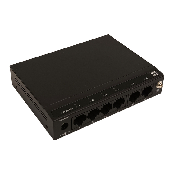
Board Diagram
LED Indicator
Front
(10* Link/Act-Green, 8* PoE-Orange, 1* PWR-Green)
(8-Port)
DC Jack
PoE Downlink Port
(4-Port)
LED Indicator
(6* Link/Act-Green, 4* PoE-Orange, 1* PWR-Green)
PoE Downlink Port
DC Jack
Rear
(8-Port)
CCT V
VLAN
D EFAULT
(4-Port)
CCT V
VLAN
D EFAULT
Notice
The equipment must be anti-th under ground connected, otherwise the equipment protection will be
greatly reduced, please use 20AWG or thicker wire to connect grounding terminal to the ground.
Installation Steps
Please check the following items before installation, if missing, please contact the dealer.
PoE Switch
Power Adapter
AC Power Cable
User Manual
Please follow installation steps as below
1) Please turn off the signal source and the device's power, installing with power on may damage
the device.
2) Use network cables to connect IP cameras with the product's 1~4/8 RJ45 Ethernet ports.
3) Use another network cable to connect switch's UPLINK port with NVR or computer.
4) Connect switch with power adapter.
5) Make sure the installation is correct, no damage for the device , and all the connections are
reliable, then power up the system.
6) Make sure the power supply of every network device works normally.
4+2/8+2 PoE Switch
Grounding
Uplink RJ45 Port
PoE
6
Link
Grounding
6
Uplink RJ45 Port
DIP Switch
DIP Switch
1pcs
1pcs
1pcs
1pcs
2
Advertisement

Related Manuals for UTEPO SF6P-FHM


Summary of Contents for UTEPO SF6P-FHM
- Page 1 4+2/8+2 PoE Switch 10/100Mbps Switch with 4/8-Port PoE Board Diagram 13.238.101.1932 User Manual V1.1 LED Indicator Front (10* Link/Act-Green, 8* PoE-Orange, 1* PWR-Green) (8-Port) Providing 4/8*10/100Base-TX PoE RJ45 ports and 2*10/100Base-TX uplink RJ45 ports, the output PoE power of single port can be up to 30W, and the total PoE budget is 60W(4 ports) / 120W (8 ports).
- Page 2 4+2/8+2 PoE Switch 4+2/8+2 PoE Switch 连接接口 连接接口 Specifications After-service(Please cut the warranty card along the dotted line) 连接接口 4*10/100Mbps PoE+ 8*10/100Mbps PoE+ Products Warranty Card 2*10/100Mbps Uplink Switch 2*10/100Mbps Uplink Switch Customer Name 4*10/100Base-TX (PoE) 8*10/100Base-TX (PoE) Ethernet Ports Address 2*10/100Base-TX Ethernet Ports Tel.
Need help?
Do you have a question about the SF6P-FHM and is the answer not in the manual?
Questions and answers