Table of Contents
Advertisement
Quick Links
Advertisement
Table of Contents

Subscribe to Our Youtube Channel
Related Manuals for UTEPO UTP7624GS-L3


Summary of Contents for UTEPO UTP7624GS-L3
- Page 1 24 Ports Gigabit SFP (10G SFP uplink) L3 Managed Switch Quick setup wizard...
-
Page 2: Table Of Contents
Content 1 Product Introduction Overview Product Feature Board Diagram Specification Installation Shipping List Installation Precautions 2.2.1 Safety Precautions 2.2.2 Installation Requirements The Requirements of Electromagnetic Environment 2.2.3 Installation Way 2.3.1 Rack Installation 2.3.2 Workbench Installation 2.3.3 Wall-hung Installation Cable Connection 2.4.1 Device Connection 2.4.2... -
Page 3: Product Introduction
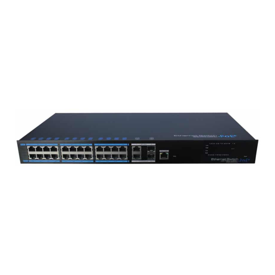
1 Product Introduction Board Diagram 1.1 Overview Power module1 Power module2 AC Power input AC Power input The 24 Gigabit ports managed Ethernet switch, which provide 24 Gigabit SFP slots , 8 * 10/100/1000 RJ45 combo ports , and 4* 1000/10G uplink SFP slots . The product support Web layer-3 network management . -
Page 4: Specification
1.4 Specification 2 Installation Description Item Caution Power Supply AC power module(redundant power, support 2 modules) Power Voltage Range 100 240V 50/60Hz Anti-counterfeiting label is attached to switch's cover. Product damage Consumption caused by unauthorized disassembly is not covered under warranty. 8 ports:10/100/1000Mbps RJ45 Auto-MDI/MDI-X or 1000Base-X SFP 24 ports:1000Base-X SFP 2.1 Package List... -
Page 5: Installation Requirements
2.3 Installation Way Pull out the power plug before cleaning the switch. Do not use wet cloth nor liquid to wipe or wash the switch; There are 3 installation ways: rack, workbench and wall-hung installation. Do not leave the switch close to water or wet place so as to prevent water or dampness from entering into the switch;... -
Page 6: Workbench Installation
Figure 2-3 Hangers installation diagram (2) Drill holes on the strong position of wall and then drive the rubber plug into the hole; (3) Drive these screws into the hole for the rack and fix the product by aiming at the rubber plug . -
Page 7: Cable Connection
3 Function Configuration Guide 2.4 Cable Connection 3.1 Computer Requirements 2.4.1 Device Connection U s e c r o s s n e t w o r k c a b l e o r c r o s s - o v e r c a b l e t o c o n n e c t P C o r Make sure the management PC has already been installed with Ethernet adapter;... -
Page 8: Confirm The Network Connection By Ping Command
3.2.2 Confirm the Network Connection by Ping Command (2) Click <property> button, enter "local connection property" window. Operation Steps below: (1) Click <Start> button to enter [Start] menu, select [Run], pop out the dialog. (2) Input "ping 192.168.1.200", click <confirm> button. If there is equipment response show in the pop out dialog, that means network connection succeed, otherwise please check if the network... -
Page 9: Web Page Configuration Guide
(2) Select “connection” tabs in [Internet Caution option] window, and click [LAN Setting] button. Please follow the steps to check if the switch is installed correctly: (1) Whether the physical connection of the equipment is correct? Use network cable to connect the product’s Ethernet port(except the console port) with managed computer network card, and ensure the link LED of the port is on. - Page 10 Environment protection This product design is environmental friendly and the product should be stored, used and dicarded in accordance with relevant national legal / regulatory requirements.
Need help?
Do you have a question about the UTP7624GS-L3 and is the answer not in the manual?
Questions and answers