Table of Contents
Advertisement
Quick Links
Packing List
Please check the following items after unpacking, if any missing, please
contact your local dealer.
No.
Items
Quantity
1
Switch
1
2
Power Cable
1
3
Console cable
1
4
Grounding cable
1
5
Rack mount brackets
2
6
Rubber pads
4
7
Screw package
1
8
Quick Installation Guide
1
9
Warranty card
1
10
QC card
1
Safety Information
Before performing an operation, read the following operation instructions and
precautions to be taken, and follow them to prevent accidents.
2.1 General Requirements
Only qualified and skilled personnel must install, configure, and unmount
the device. The device must not be disassembled.
When operating the device, obey the local safety regulations. The safety
precautions provided in the document are supplementary and shall be in
compliance with the local safety regulations.
When operating the device, in addition to the precautions (please see the
notes below), follow the specific safety instructions.
The installation and maintenance personnel need to understand the basic
safety precautions to be taken.
Do not block the ventilation while the device is running. Keep a minimum
distance of 5 cm from the ventilation to the walls or the other objects that
block the ventilation.
Do not operate the device in an area that exceeds the maximum
recommended ambient temperature.
Do not place the device in the environment that has inflammable and
explosive air or fog. Do not perform any operation in this environment.
2.2 Electric Safety
During the installation of the AC power supply facility, follow the local safety
regulations. The personnel who install the AC facility must be qualified to
perform high voltage and AC operations.
Before touching the device or hand-operating parts, wear a grounded
electrostatic discharge (ESD) wrist strap. It can prevent the sensitive
components from damage by the static electricity in the human body.
2.3 Optical Safety
When handling optical fibers, do not stand close to, or look at the optical
fiber outlet directly with unaided eyes.
Cutting and splicing fibers must be performed by the trained personnel only.
Before cutting or splicing a fiber, ensure the fiber is disconnected from the
optical source. After disconnecting the fiber, use protecting caps to protect
all the optical connectors.
Product Introduction
3.1 Overview
This series of switches is enterprise-class stackable routing switch with fixed,
built-in 10GbE uplink ports. It has great performance on availability, scalability,
security and energy efficiency. This fully managed switch provides high
switching capacity, supports wire-speed L2/L3 forwarding and high routing
performance for IPv4 and IPv6 protocols. Thanks to the VSF (Virtual Switch
Framework), the management work for the network administrator is simplified.
Multiple switches can be virtualized into one logical device, achieving the
sharing of information and data tables between different switches, which
provides more reliability. It delivers high-performance, hardware-based on IP
routing. RIP, OSPF, and BGP provide dynamic routing by exchanging routing
information with other Layer 3 switches and routers. It is ideal for aggregation
or access layer for campus, enterprise, government and internet service
provider networks.
-1-
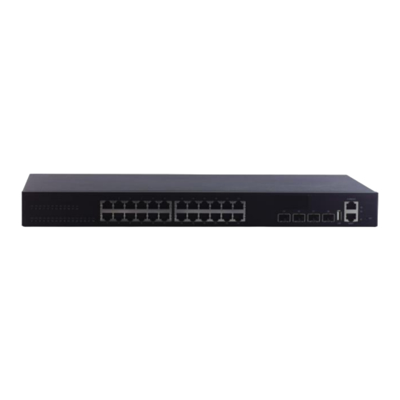
3.2 Hardware Introduction
28-Port Switch
28-Port PoE Switch
52-Port Switch
52-Port PoE Switch
LED Indicators Instructions
LED Symbol
Status
Description
On (Green)
Power is operating normally
PWR
Off
Power is not operating
On(Green,
System is loading
blink)
DIAG
On (Green)
System is operating normally
On (Green)
DC power is operating normally
RPS
Off
DC power is not operating
On (Green)
PoE is operating normally
PoE
Off
PoE is not operating
Network management port 10M /
On (Green)
100M / 1G is linking
Network management port is not
MGMT
Off
linking
Blink
Data forwarding
Installations
This series switch supports three installation modes:
Rack mounted installation
Desktop installation
Wall mounted installation
4.1 Rack Mounted Installation
This switch supports 19" rack mounted installation. Following with the
installation steps below.
Step 1: Fix the provided rack mounted hangers to the left and right
Accessories
side of the device using 4 screws each. Use the four holes on the
left and right side of the device.
Step 2: Install the switch to the rack. The distance between the devices in the rack
should be more than 5cm.
-2-
4.2 Desktop Installations
This series of switches support desktop installation. Users can put this product
on clean, stable, grounded workbench.
Please follow the steps below:
Carefully put the device upside down, clean the grooves on the chassis
backplane with soft cloth to make sure there is no oil or dust in it.
Remove the stickers on the foot pad, paste the foot pad on the four corners
at the bottom of the switch.
Carefully put the device upright on the workbench.
4.3 Wall-mounted Installations
Drill 4 holes on the wall where the device is installed according to the
dimensions of the switch and accessories. Insert an expansion anchor into
each hole drilled in the wall, and beat the top of it with a rubber hammer until
all the anchor is inserted into the wall.
Please follow the steps below:
Fix the provided rack mounted hangers to the left and right side of the device
using 4 screws each. Use the four holes on the left and right side of the device.
Fix to the switch to the wall.
Connect the Power Supply
Note:
Ground the switch housing with the grounding screw on the side of the
housing! Always make the ground connection first and disconnect it at the end.
Use one end of PGND cable to connect the M4 grounding connector of the
switch, the other end to a ground point. The PGND of the switch is shorted to
the copper protection ground bar provided by the user. The PGND cable used
should be an alternating yellow and green plastic insulating one with copper
core, with cross-sectional area greater than 2.5mm² .
The figure below takes rack-mounted installation as example.
Ground the switch housing
-3-
This series switch supports 100~240V AC power supply.
100~240 V AC Supply
Use an AC power cable to connect the AC power connector of the switch. It is
recommended to use the AC power cable provided in the package. Connect
the mains supply to the building's power supply network.
Please observe the following specifications:
Items
Specifications
Input Voltage
100~240V AC, 50~60Hz
5.1 Starting Up
After connection to the power supply, the switch starts automatically. LED
indicators "PWR" turns green, and after about 90s, the system is ready.
Note:
To switch off the device, always disconnect both the main and redundant
power supply.
Factory Settings
Note:
Please note that the factory settings may change with future firmware versions.
For this reason we recommend that you check the release notes for
information about any changes to the factory settings before carrying out a
firmware update.
The switch starts with its factory settings:
Items
Specifications
Management Interfaces
Enabled
Baud rate: 115200 bit/s
Data bits: 8
Console Port
Parity: none
Stop bits: 1
Flow control: none
Enable
Default static IP address: 192.168.1.200
Web Manager
Default subnet mask: 255.255.255.0
User: admin
Password: admin
Disable, to enable the Telnet, users should
Telnet
configure the IP addresses for the switch and
start the Telnet Server function on the switch.
Access Network Management
After starting up successfully, connect the switch to your local network
segment using a suitable cable to access the switch network management
system. For details, please refer to the following document:
Management Configuration Guide
Describes network management system configuration instructions.
Specifications
Items
28-Port Switch
28-Port PoE Switch
Hardware Specifications
20*10/100/1000 Base-T
PoE+ RJ-45 ports
24*10/100/1000
Downlink Port
Base-T RJ-45 ports
4*1000Mbps Combo
(RJ-45/SFP)
Uplink Port
4*10GE Base-X SFP+
1*RJ-45 Ethernet management port
1*Console port
Management
Port
1*Reset port
1*USB2.0 interface
Cable
Cat5 or better
Dimensions
440mm*320mm*44mm
(W*D*H)
AC: 100~240VAC,
AC: 100~240VAC,
Power Supply
50~60Hz
50~60Hz
Power
<471W(Full load, include
<30W(Full load)
Consumption
PoE)
Material
Metal shell
Switch Property
Forwarding
Store and Forward
Modes
-4-
Advertisement
Table of Contents

Related Manuals for UTEPO UTP5628S-L3


Summary of Contents for UTEPO UTP5628S-L3
- Page 1 This series switch supports 100~240V AC power supply. Packing List 3.2 Hardware Introduction 100~240 V AC Supply Please check the following items after unpacking, if any missing, please 28-Port Switch Use an AC power cable to connect the AC power connector of the switch. It is contact your local dealer.
- Page 2 Switching 128Gbps, non-blocking Capacity Packet 95Mpps Forwarding Rate Jumbo frame MAC Table 16K, supported auto learning 24-Port Gigabit 4-Port 10G SFP+ L3 Managed ARP Table Ethernet Switch Routing Table 20-Port Gigabit PoE+ 4-Port Gigabit Combo 4- ACL Table Port 10G SFP+ L3 Managed Ethernet Switch PoE Standard IEEE 802.3af/at 48-Port Gigabit 4-Port 10G SFP+ L3 Managed...
Need help?
Do you have a question about the UTP5628S-L3 and is the answer not in the manual?
Questions and answers