Table of Contents
Advertisement
Quick Links
Advertisement
Table of Contents

Subscribe to Our Youtube Channel
Related Manuals for Insportline Petyr ET


Summary of Contents for Insportline Petyr ET
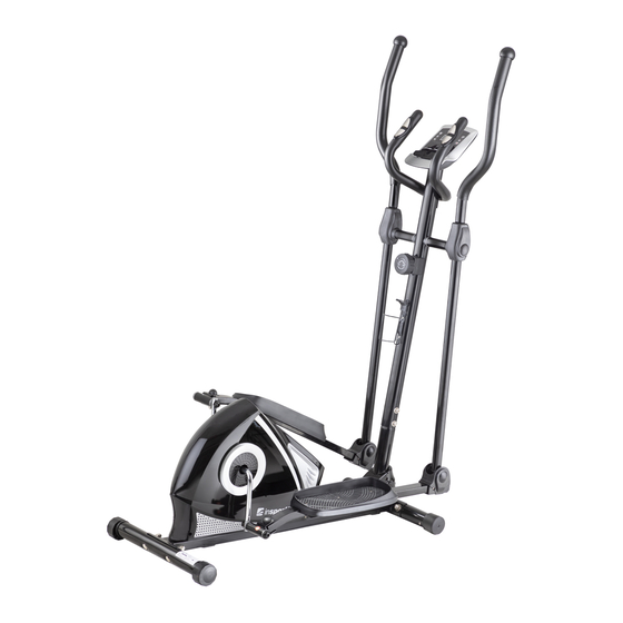
- Page 1 USER MANUAL – EN IN 20105 Elliptical trainer inSPORTline Petyr ET...
-
Page 2: Table Of Contents
CONTENTS SAFETY INSTRUCTIONS ........................3 IMPORTANT NOTES ..........................3 ASSEMBLY ............................. 4 CONSOLE ............................. 10 TROUBLESHOOTING .......................... 11 USE OF ELEPTICAL TRAINER ......................11 THE WARM UP PHASE ........................11 MAINTENANCE ............................ 12 ENVIRONMENT PROTECTION ......................12 DIAGRAM .............................. 13 PARTS LIST ............................ -
Page 3: Safety Instructions
SAFETY INSTRUCTIONS • Read the manual carefully before first use and keep it for future reference. • To ensure the best safety of the exerciser, regularly check it on damages and worn parts. • If you pass on this exerciser to another person or if you allow another person to use it, make sure that that person is familiar with the content and instructions in these instructions. -
Page 4: Assembly
contents of the delivery is complete by referring to the parts list of the assembly and operating instructions. • Be sure to set up the exerciser in a dry and even place and always protect it from humidity. If you wish to protect the place particularly against pressure points, contamination, etc., it is recommended to put a suitable, non-slip mat under the exerciser. - Page 5 TOOLS Allen key S6 – 1 pcs Allen key S8 – 1 pcs Multifunction wrench – 1 pcs Multifunction wrench S10, S13, S14, S15 – 1 pcs STEP 1 Secure the front stabilizer (10) to the main frame (1) using the 2 screws (61) of 2 washers (62) and 2 nuts (63).
- Page 6 STEP 2 Remove the 6 screws (20), 6 washers (66) from the main frame (1). Insert the voltage cable (69) through the bottom hole of the front pillar (8) and pull it through the top hole of the front post (8). Connect the sensor cable (67) from the main frame (1) to the sensor cable I (14) from the front post (8).
- Page 7 STEP 3 Remove the 2 screws (23), 2 washers (24, 25, and 26) from the right and left sides of the center post (8). Attach the left handlebar holder (6) to the left side of the post (8) with the screw (23) and washers (24, 25, 26) that you removed.
- Page 8 STEP 4 Attach the left / right handle (6, 7) to the left / right handle holder (4, 5) with 4 screws (28), 4 washers (30). Attach left handrail cover A (32) and left handrail cover B (33) to left handrail (4) with 4 screws (31). Attach Right Handle Cover A (34) and Right Handle Cover B (35) to Right Handle (5) with 4 Screws (31)
- Page 9 STEP 5 Remove the 4 screws (13) from the back of the console (12). Remove the 2 screws (20) and 2 washers (19) from the front post (8). Insert the sensor cables (15) from the handles (9) into the hole in the front pillar (8) and pull the top of the post (8).
-
Page 10: Console
CONSOLE DISPLAY 00:00 – 99:59 min:sec TIME 0,0 – 999,9 km/h, mil/h SPEED DISTANCE 0,00-99,99 km, mil CALORIES 0,0-999,9 kcal ODOMETR if available 0,00-99,99 km, mil PULSE if available 40-200 beats/min BUTTONS MODE / SELECT Confirm button, hold for 4 seconds to reset all values except ODOMETR. -
Page 11: Troubleshooting
PULSE, PUL if available Display heart rate, the user must hold the pulse measurement plates SCAN Displays functions: TIME, SPEED, DISTANCE, CALORIES, PULSE, ODOMETR BATTERY: The console uses two AA batteries, one AAA battery or one 1.5V battery. TROUBLESHOOTING Elliptical is not stable Level the elliptical with the leveling feet The console does not display data Check cable condition and connection... -
Page 12: Maintenance
Hamstring stretched Sit and outstretch your right leg. Rest the sole of your left foot against the inside of your right tight. Stretch out your right arm along your right leg as far as you can. Hold for 15 seconds and relax. Repeat all with your left leg and left arm. -
Page 13: Diagram
DIAGRAM... -
Page 15: Parts List
PARTS LIST Name Qty. Name Qty. Grommet Ø29 x Ø16x14 Main frame Foot holder cover – B Left footrest Foot holder cover – A Right footrest Screw Ø15.8x62.5xM8 Left handlebar support Big washer Ø8xØ20x2.0 Right handlebar support Left handlebar Screw M8x20 Right handlebar Screw ST4.2*25 Front pillar... -
Page 16: Terms And Conditions Of Warranty, Warranty Claims
Screw ST4.8x15 Freewheel holder Screw ST4.2x25 Screw M8*10 Nut 7/8" Bearing 6000ZZ Washer Ø23xØ34.5x2.5 Washer Ø6*Ø12*1 Bearing nut I 7/8" Screw M6*10 Bearing Screw M8*30 Washer Ø10.2*Ø14*1 Bearing sleeve Bearing nut I 15/16" Rubber stop Washer I Ø24x40x3.0 Screw ST2.9x12 Pulley with crank Left chain cover Belt... - Page 17 By the Warranty for Goods Quality, the Seller guarantees that the delivered Goods shall be, for a certain period of time, suitable for regular or contracted use, and that the Goods shall maintain its regular or contracted features. The Warranty does not cover defects resulting from (if applicable): •...
Need help?
Do you have a question about the Petyr ET and is the answer not in the manual?
Questions and answers