Table of Contents
Advertisement
Quick Links
www.ti.com
User's Guide
DRV821xEVM and DRV8220EVM User's Guide
This document is provided with the DRV82xx family customer evaluation modules (EVM) as a supplement to the
DRV8210, DRV8212, and DRV8220 data sheets. This user's guide describes the hardware implementation of
the EVM.
Hot surface. Contact may cause burns. Do not Touch.
DRV8210EVM and DRV8212EVM are rated for power supply voltages between 1.65 VDC and 11
VDC max. The DRV8210 can support peak output currents up to a maximum of 1.6 ADC and the
DRV8212 can support peak output currents up to a maximum of 4 ADC. To maintain component
temperatures below the 130°C rating of the printed circuit board material, TI requires that the
continuous current of both channels be limited to 0.9 A-RMS when operating for extended periods of
time at an ambient temperature of 25°C.
1
Introduction.............................................................................................................................................................................3
2 Power Connectors..................................................................................................................................................................
Points...............................................................................................................................................................................5
4.1 PH/EN Control Mode (MODE=Logic High)........................................................................................................................
4.2 PWM Control Mode (MODE = Logic High, DRL, PDSG)...................................................................................................
Sensing....................................................................................................................................................................10
EVM............................................................................................................................................................11
6.1 Dual Motor Operation.......................................................................................................................................................
6.2 Single Motor Operation....................................................................................................................................................
8 Revision History...................................................................................................................................................................
Trademarks
™
™
MSP430
and eZ-FET
All trademarks are the property of their respective owners.
SLOU540A - NOVEMBER 2020 - REVISED DECEMBER 2020
Submit Document Feedback
ABSTRACT
Table of Contents
Potentiometers.......................................................................................6
(MODE=Hi-Z).......................................................................................................9
Drivers...........................................................................................................14
are trademarks of Texas Instruments.
Copyright © 2020 Texas Instruments Incorporated
CAUTION
DRV821xEVM and DRV8220EVM User's Guide
Table of Contents
3
7
8
11
13
15
1
Advertisement
Table of Contents

Related Manuals for Texas Instruments DRV821 EVM Series


Summary of Contents for Texas Instruments DRV821 EVM Series
-
Page 1: Table Of Contents
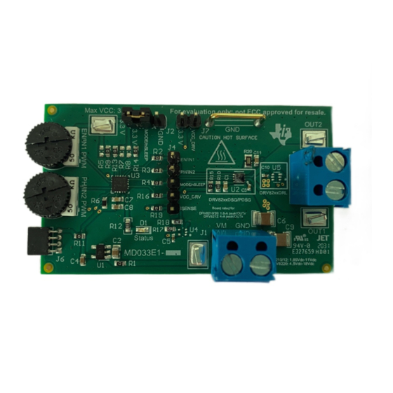
™ MSP430 and eZ-FET are trademarks of Texas Instruments. All trademarks are the property of their respective owners. SLOU540A – NOVEMBER 2020 – REVISED DECEMBER 2020 DRV821xEVM and DRV8220EVM User's Guide Submit Document Feedback Copyright © 2020 Texas Instruments Incorporated... - Page 2 PCB (Top-Assembly View) www.ti.com PCB (Top-Assembly View) Figure 1-1. PCB (Top 3-D View) Figure 1-2. PCB (Assembly View) DRV821xEVM and DRV8220EVM User's Guide SLOU540A – NOVEMBER 2020 – REVISED DECEMBER 2020 Submit Document Feedback Copyright © 2020 Texas Instruments Incorporated...
-
Page 3: Introduction
2-1. We recommend a pin header with pin dimensions similar to the Digikey part number 850-10-050-20-001000. The U1 MCU must be removed from the Launchpad. SLOU540A – NOVEMBER 2020 – REVISED DECEMBER 2020 DRV821xEVM and DRV8220EVM User's Guide Submit Document Feedback Copyright © 2020 Texas Instruments Incorporated... - Page 4 Power Connectors www.ti.com Figure 2-1. MSP-EXP430FR5969 LaunchPad connected to EVM DRV821xEVM and DRV8220EVM User's Guide SLOU540A – NOVEMBER 2020 – REVISED DECEMBER 2020 Submit Document Feedback Copyright © 2020 Texas Instruments Incorporated...
-
Page 5: Test Points
TP6 and TP7 OUT1 and OUT2 test points VM test point VCC (3.3 V LDO output) test point. SLOU540A – NOVEMBER 2020 – REVISED DECEMBER 2020 DRV821xEVM and DRV8220EVM User's Guide Submit Document Feedback Copyright © 2020 Texas Instruments Incorporated... -
Page 6: Mode/Nsleep Jumper And Speed-Adjustment Potentiometers
PWM potentiometers. The tables below show how to configure the potentiometers for each MODE configuration. Figure 4-1. MODE /nSLEEP header and PWM Potentiometers DRV821xEVM and DRV8220EVM User's Guide SLOU540A – NOVEMBER 2020 – REVISED DECEMBER 2020 Submit Document Feedback Copyright © 2020 Texas Instruments Incorporated... -
Page 7: Ph/En Control Mode (Mode=Logic High)
PWM - set IN1 PWM pot HIGH - turn IN2 PWM pot Forward (OUT1 -> OUT2) in any position completely clockwise SLOU540A – NOVEMBER 2020 – REVISED DECEMBER 2020 DRV821xEVM and DRV8220EVM User's Guide Submit Document Feedback Copyright © 2020 Texas Instruments Incorporated... -
Page 8: Pwm Control Mode (Mode = Logic High, Drl, Pdsg)
HIGH- turn PH/IN2 Brake, (Low-Side nSLEEP pin to 3.3V PWM pot completely PWM pot completely Slow Decay) pin) clockwise clockwise DRV821xEVM and DRV8220EVM User's Guide SLOU540A – NOVEMBER 2020 – REVISED DECEMBER 2020 Submit Document Feedback Copyright © 2020 Texas Instruments Incorporated... -
Page 9: Independent Half-Bridge Control Mode (Mode=Hi-Z)
PWM - turn INx PWM pot in any position PWM = 0 -> OUTx Low-Side ONPWM = 1 -> OUTx High-Side ON SLOU540A – NOVEMBER 2020 – REVISED DECEMBER 2020 DRV821xEVM and DRV8220EVM User's Guide Submit Document Feedback Copyright © 2020 Texas Instruments Incorporated... -
Page 10: Current Sensing
AMP_OUT is connected to an ADC pin on the MCU to monitor the current and to create current sensing algorithms. Figure 5-1. Current Sensing Schematic DRV821xEVM and DRV8220EVM User's Guide SLOU540A – NOVEMBER 2020 – REVISED DECEMBER 2020 Submit Document Feedback Copyright © 2020 Texas Instruments Incorporated... -
Page 11: Operation Of The Evm
GND) or counter-clockwise (if motor originally connected to VCC) before powering on the board and then slowly turning the EN/IN1 PWM potentiometer in the opposite direction to increase the motor speed. SLOU540A – NOVEMBER 2020 – REVISED DECEMBER 2020 DRV821xEVM and DRV8220EVM User's Guide Submit Document Feedback Copyright © 2020 Texas Instruments Incorporated... - Page 12 0.1 …F OUT1 MODE Thermal OUT2 Figure 6-3. Half-bridge mode used as a high-side driver with outputs paralleled DRV821xEVM and DRV8220EVM User's Guide SLOU540A – NOVEMBER 2020 – REVISED DECEMBER 2020 Submit Document Feedback Copyright © 2020 Texas Instruments Incorporated...
-
Page 13: Single Motor Operation
0.1 …F Bulk Controller DRV821xDSG 0.1 …F OUT1 MODE Thermal OUT2 Figure 6-5. DRV821xDSG PWM single motor operation SLOU540A – NOVEMBER 2020 – REVISED DECEMBER 2020 DRV821xEVM and DRV8220EVM User's Guide Submit Document Feedback Copyright © 2020 Texas Instruments Incorporated... -
Page 14: Removing And Installing Supported Motor Drivers
Device ID resistors to populate DRV8210DSG ID1=0; ID2=0; ID3=0 R9, R13, R14 DRV8210PDSG ID1=0; ID2=0; ID3=1 R9, R13, R8 DRV821xEVM and DRV8220EVM User's Guide SLOU540A – NOVEMBER 2020 – REVISED DECEMBER 2020 Submit Document Feedback Copyright © 2020 Texas Instruments Incorporated... -
Page 15: Revision History
NOTE: Page numbers for previous revisions may differ from page numbers in the current version. Changes from Revision * (November 2020) to Revision A (December 2020) Page • Updated Caution information..........................SLOU540A – NOVEMBER 2020 – REVISED DECEMBER 2020 DRV821xEVM and DRV8220EVM User's Guide Submit Document Feedback Copyright © 2020 Texas Instruments Incorporated... - Page 16 TI products. TI’s provision of these resources does not expand or otherwise alter TI’s applicable warranties or warranty disclaimers for TI products. Mailing Address: Texas Instruments, Post Office Box 655303, Dallas, Texas 75265 Copyright © 2020, Texas Instruments Incorporated...
Need help?
Do you have a question about the DRV821 EVM Series and is the answer not in the manual?
Questions and answers